Simpson S661 User manual

S661
Rate Counter
Operation Manual
www. .com information@itm.com1.800.561.8187

Warranty and Returns
SIMPSON ELECTRIC COMPANY warrants each instrument and other articles manufactured
by it to be free from defects in material and workmanship under normal use and service, its
obligation under this warranty being limited to making good at its factory or other article of
equipment which shall within one (1) year after delivery of such instrument or other article of
equipment to the original purchaser be returned intact to it, or to one of its authorized service
centers, with transportation charges prepaid, and which its examination shall disclose to its
satisfaction to have been thus defective; this warranty being expressly in lieu of all other war-
ranties expressed or implied and of all other obligations or liabilities on its part, and SIMPSON
ELECTRIC COMPANY neither assumes nor authorizes any other persons to assume for it any
other liability in connection with the sales of its products.
This warranty shall not apply to any instrument or other article of equipment which shall have
been repaired or altered outside the SIMPSON ELECTRIC COMPANY factory or authorized
service centers, nor which has been subject to misuse, negligence or accident, incorrect wiring
by others, or installation or use not in accord with instructions furnished by the manufacturer.
Under the normal eld usage there is no need to remove the front bezel of this product. The
front bezel of this product should only be removed by a qualied technician.
About this Manual
To the best of our knowledge and at the time written, the information contained in this
document is technically correct and the procedures accurate and adequate to operate this
instrument in compliance with its original advertised specications.
Notes and Safety Information
This Instruction Manual contains warning headings that alert the user to check for hazardous
conditions. These appear throughout this manual where applicable, and are dened below.
To ensure the safety of operating performance of this instrument, these instructions must be
adhered to.
Warning, refer to accompanying documents.
Caution, risk of electric shock.
Attention, consulter les documents d’accompagnement.
Attention, risque de choc électrique.
1
www. .com information@itm.com1.800.561.8187

2
Contents
1Product Description. ............................................3
1.1 General Description. .........................................3
1.2 Part Number Identification. ....................................4
1.3 Option Module Summary. .....................................4
2Hardware Setup. ..............................................6
2.1 Panel Installation. ...........................................6
2.2 Removing / Installing Option Modules. ...........................7
2.3 120/240 VAC Power Module. ..................................8
2.4 Standard Input Module. .......................................8
2.5 Quadrature Input Module. ....................................11
2.6 Excitation Module. ..........................................14
2.7 Single and Dual Relay Modules. ...............................15
3 Display & Keypad Controls. .....................................16
3.1 Display. ..................................................16
3.2 Display Error Messages. .....................................17
3.3 What the Keys Do in Display Mode. ............................18
3.4 What the Keys Do in the Programming Mode. ....................18
3.5 Special Start-UpModes. .....................................21
4 Counter Operations and Parameters. .............................21
4.1 Password and Security Controls. ..............................22
4.2 A/B
Channel Options. .......................................23
4.3 Rate (Frequency) Scaling and Display. ..........................25
4.4 Output Control Modes. ......................................27
4.5 Set Point Parameters. .......................................28
4.6 Miscellaneous Controls. ......................................2 9
Appendix A:Technical Specifications. ..............................30
A.1 Functional Specifications. ....................................30
A.2 Electrical, Environmental and Mechanical Specifications. ...........31
Appendix B:Programming Quick Reference. .........................33
www. .com information@itm.com1.800.561.8187

3
1 Product Description
1.1 General Description
The S661 rate counter fits a 1/8 DIN standard cutout and is perfect for tight spaces,
extending only 3.24” (82mm) behind the panel. The unit is UL listed. The unit is for in-
door use at altitudes up to 2000m, temperatures between 0° and 40°C and installation
category III, pollution degree 2.
The counter is powered from 120 or 240 VAC. The nonvolatile EEPROM retains all
programming and count information when power is removed or interrupted.
Display scaling, preset values and all menu functions are easily programmed from the
front panel, following easy-to-use word prompts. Front panel reset disable and pass-
word lockout protection features guard against unauthorized or accidental changes.
The counter accepts count rates up to 30 kHz and pulses from different types of sen-
sors, including Quadrature, CMOS or TTL circuits and PNP or NPN devices.
The optional, field-replaceable single/dual relay module enhances the counter from a
passive display device to an integral control element for your application. The counter
has latching, boundary or timed (0.01 to 599.99 seconds) output modes.
An optional 12 VDC (100mA) excitation output module can provide power for external
sensors.
www. .com information@itm.com1.800.561.8187

4
1.2 Part Number Identification
The following matrix indicates the configuration of your S661counter.
1.3 Option ModuleSummary
Figure 1. Option Module Slots (Rear View)
The S661is amodular product which uses field configuring slide-in modules. The
modules slide easily into the rear of the counter.
Figure 1displays the functional assignments for each module position.
125
4
Input ExcitationPower
Supply
Output
Input
Standard
Quadrature
Power Supply
Basic Unit
S661 120 VAC
240 VAC
1
2
1
2
Excitation
None
12VDC
0
1
Other
None 0
Output
None
One relay
Two Relays
0
1
2
www. .com information@itm.com1.800.561.8187
5
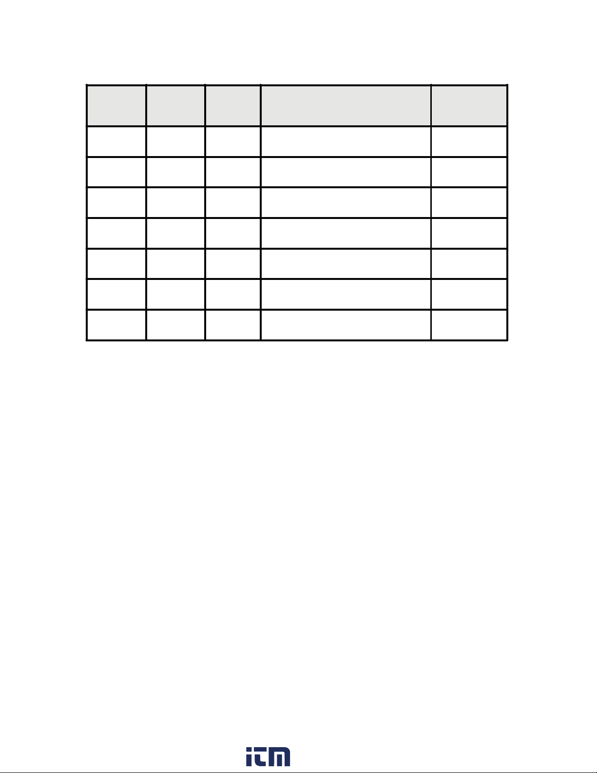
Table 1 describes available option modules for the S661.
Table 1. Option Module Summary
Module
slot Type P/N Description See
Section
1Input Standard Input Module 2.4
1Input Quadrature Input Module 2.5
2Ext4506412 VDC Excitation Module 2.6
4Power 120 VAC Power Module 2.3
4Power 240 VAC Power Module 2.3
5Output 45062Dual Relay Module 2.7
5Output 45063Single Relay Module 2.7
www. .com information@itm.com1.800.561.8187

6
2 Hardware Setup
2.1 PanelInstallation
The S661 1/8 DIN counter requires a standard 1/8 DIN panel cutout of 1.77” (45mm)
high by 3.62” (92mm) wide. To install the counter into a panel cutout, remove the clips
from the side of the counter. Slide the counter through your panel cutout, then slide
the mounting clips back on. Press evenly to ensure a proper fit.
Figure 2. Counter and Panel Cut-Out Dimensions
Figure 3. Panel Mounting Clips
%
2.04"
51.8mm
.52"
13.2 mm
ENTER
RESET
1.77"
45mm
3.24"
82mm
3.62"
92mm
1.74"
44mm
3.93"
99.8 mm
www. .com information@itm.com1.800.561.8187
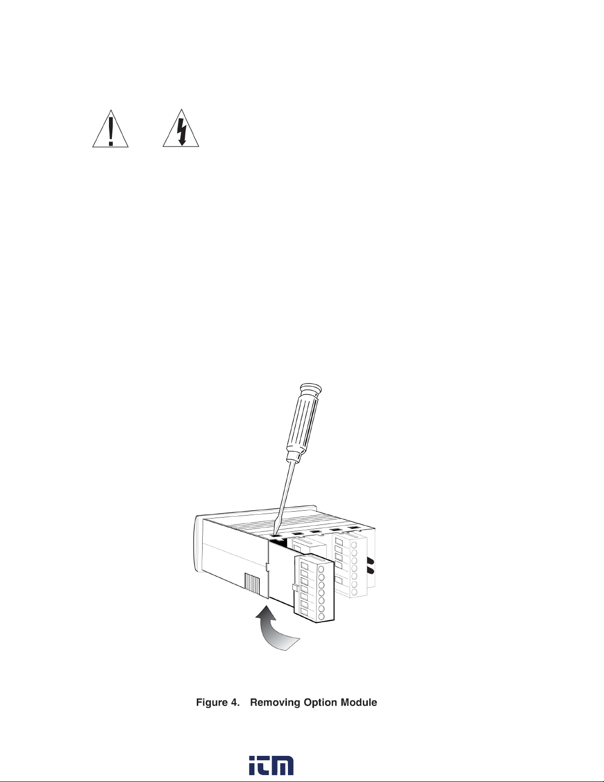
1. Remove module from case by inserting a screwdriver into tab slot opening at top of input
module. Apply pressure to release module from case. Repeat procedure for tab located on
underside of module and then slide module away from the case.
2. Refer to appropriate sections to congure switches or jumpers for proper operation.
Table 1 can be used to identify modules and their associated detail paragraph.
3. Install module by carefully aligning module edges with slots in case and pressing forward
until tabs (on top and bottom) engage.
2.2 Removing / Installing Option Modules
Shut power off before removing or installing any option modules
Couper le courant avant de retirer ou d’installer des modules optionnels
7
www. .com information@itm.com1.800.561.8187
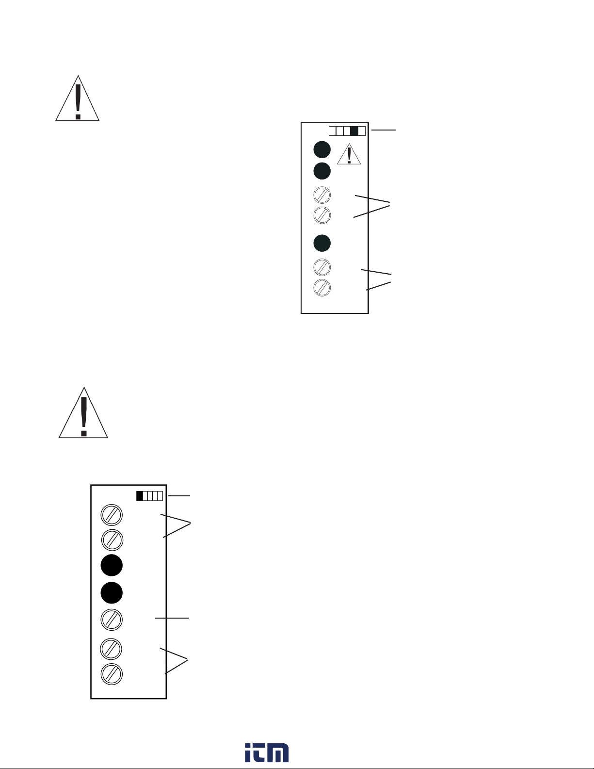
2.3 120/240 VAC Power Module
Never connect AC mains (hot or neutral) to the Reset or Common terminals!
2.4 Standard Input Module
NOTE: A fusible link is not provided on this module.
A ½ Amp Time Delay fuse, Bussman MDL ½, or similar is required.
Remove power before wiring option modules.
The AC power module allows the S661 to be
operated from standard 50/60 Hz line power.
The power module will be congured as 120
VAC or 240 VAC per markings on the back
panel. Ensure the input rating of the supply
matches your line voltage. The power supply
module has provisions for a hard-wire Alarm
Reset. This control can be a switch, relay
contact or solid state device. Actuation is
immediate upon an active Low for at least
2.5ms to this terminal. The reset circuit is
independent of the power circuit.
Figure 6. Standard Input Module
Coupez l’alimentation avant de raccorder les modules optionnels.
Ne jamais brancher sur secteur (chaudes ou neutres) pour la réinitialisation
ou terminaux communs!
Denotes module position 1 at rear of counter
Primary Input
Connect the input signal to A INPUT and COMMON
Display Hold
Active low
‘Freezes’ Display Value
Secondary Input
Direction Control or count pulse input
A INPUT
COMMON
USER
INPUT
B INPUT
IINPUT
COMMON
Denotes modules position 4 at rear
of counter
Figure 5. AC Power Module
Power Supply 120 VAC or 240 VAC
power connection
VAC
VAC
~
~
Remote Reset
Active low 0.2V performs primary
reset
RESET
COMMON
POWER
8
www. .com information@itm.com1.800.561.8187
9
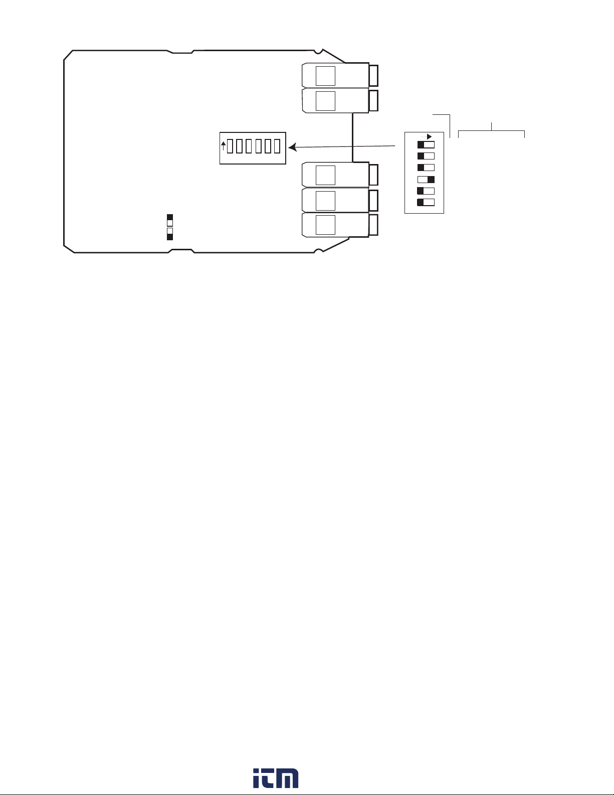
Figure 7. Standard Input Module Default Settings
DIP switch SW1, figure 7, is used to set up the counter to conform to the electrical
characteristics of the sensor or signal being detected. Switch positions 1-3 config-
ure channel B, while switches 4-6 configure channel A. These switches select bias
(threshold voltages), low pass filter (enable/disable) and sensor type (Sink or Source).
Refer to the documentation that accompanied the sensor for related information. The
sensor can most likely be matched to one of the typical switch settings shown in figure
8 and figure 8a.
Note: The input boards are designed so that selecting sourcing or sinking is
based on the type of sensor that is being used. If a PNP (sinking) sensor is be-
ing used, set the input board for sinking also (switched 3 and 6 = OFF).
If channel B is not used, default settings for switch positions 1 through 3 should be se-
lected. Default settings are provided in Table 2.
The input module also provides for a user input signal. On the S661, this input per-
forms a Display Hold. While active, the rate value shown on the display is “frozen.”
Internal measurements and output controls continue to operate.
1 2 3 4 5 6
BBias Off=Hi On=Lo
BFreq Off=Hi On=Lo
BOff= Sink On= Source
AFreq Off=Hi On=Lo
AOff= Sink On= Source
ABias Off=Hi On=Lo
CHANNEL FUNCTION
DIP Switch
(Shown for TTL Factory Settings)
Note: Refer to specifications
for DIP switch function
electrical characteristics
12345 6
Dipswitch Legend = ON
= OFF
www. .com information@itm.com1.800.561.8187

10
The S661 can accept inputs from many different sensors. The A and B channels may
be configured independently as shown in Table 2. Figures 8 and 8a have examples of
some typical sensors and the wiring connections that would be used.
Table 2. Standard Input Module DIP Switch Settings
* = Factory Default setting
1 B Channel Bias: OFF = Hi* VLT = 5.0 V VUT = 7.0V (+/- 10%)
ON = Low VLT = 1.6 V VUT = 3.6V (+/- 10%)
2 B Channel Frequency: OFF = Hi* (low pass filter disabled)
ON = Lo (low pass filter enabled)
3 B Channel Sensor: OFF = Sinking* (internal pull-up enabled)
ON = Source (internal pull-down enabled)
4 A Channel Bias: OFF = Hi VLT = 5.0 V VUT = 7.0V (+/- 10%)
ON = Low* VLT = 1.6 V VUT = 3.6V (+/-10%)
5 A Channel Frequency: OFF = Hi* (low pass filter disabled)
ON = Lo (low pass filter enabled)
6 A Channel Sensor Type: OFF = Sinking* (internal pull-up enabled)
ON = Source (internal pull-down enabled)
AINPUT
USER
INPUT
BINPUT
COMMON
COMMON
INPUT EXCITATION
ISO+12V
ISOCOM
+
_
__
---
123456
ON
PNP SENSOR
LOW BIAS
LOW FREQUENCY
SOURCING
HIGHBIAS
HIGHFREQUENCY
SINKING
AINPUT
USER
INPUT
BINPUT
COMMON
COMMON
INPUT EXCITATION
ISO+12V
ISOCOM
+
_
__
---
123456
ON
NPN SENSOR
LOW BIAS
LOW FREQUENCY
SOURCING
HIGHBIAS
HIGHFREQUENCY
SINKING
OUTPUT
COMMON
+
Figure 8. Sensor Connection Examples
www. .com information@itm.com1.800.561.8187
11
Figure 8a. Sensor Input example
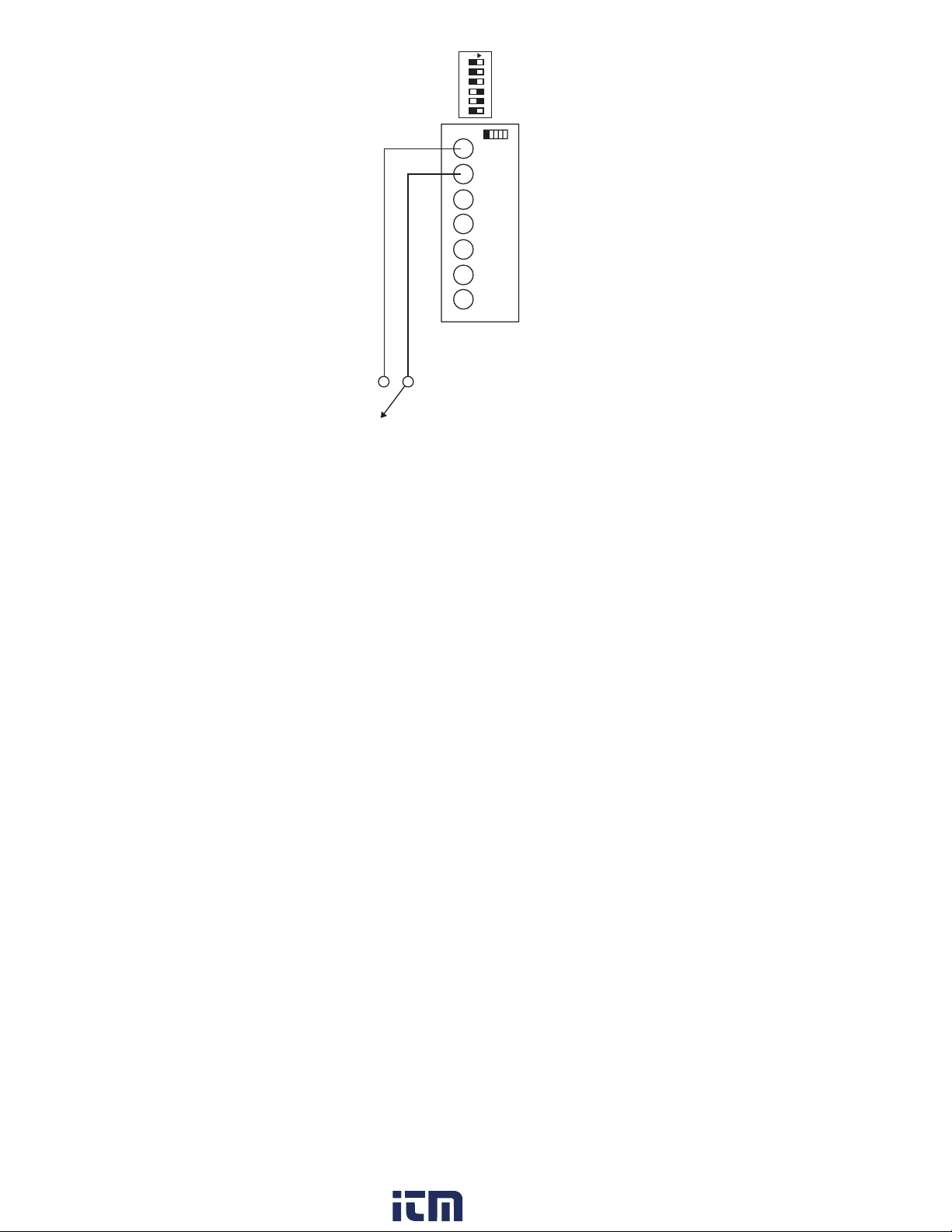
2.5 Quadrature Input Module
The Quadrature / Universal Input Module has two operational modes: Quadrature
mode and Standard mode. Quadrature mode is selected by positioning JP1 and JP2
on pins 1 and 2. Standard mode is selected by placing JP1 and JP2 on pins 2 and 3
(see Figure 10 for details). The Quadrature mode supports a wide range of encoders
including the Simpson SE series.
While in Standard mode, this module works similarly to the Standard Input module,
with the added capability to selectively invert A, B, and User input signals. The Input
module also provides for a User input signal. On the S661 this input serves as a Dis-
play Hold. While active, the rate value shown on the display is “frozen.” Internal mea-
surements and output controls continue to operate.
NOTE: If B channel is not going to be used, use the default switch settings for
SW1 positions 1 through 3. Default settings are provided in Table 3.
AINPUT
USER INPUT
BINPUT
COMMON
COMMON
INPUT
1234 5 6
ON
DRY CONTACT
LOW BIAS
LOW FREQUENCY
SOURCING
HIGHBIAS
HIGHFREQUENCY
SINKING
www. .com information@itm.com1.800.561.8187
12
In both modes, the state of the User input signal can be selected as active high or ac-
tive low. DIP switch SW1 configures the counter to match the specifications of the ac-
companyingsensor. When shipped from the factory, the counter is set for X1 quadra-
ture, as shown in Figure 10and Table 3:
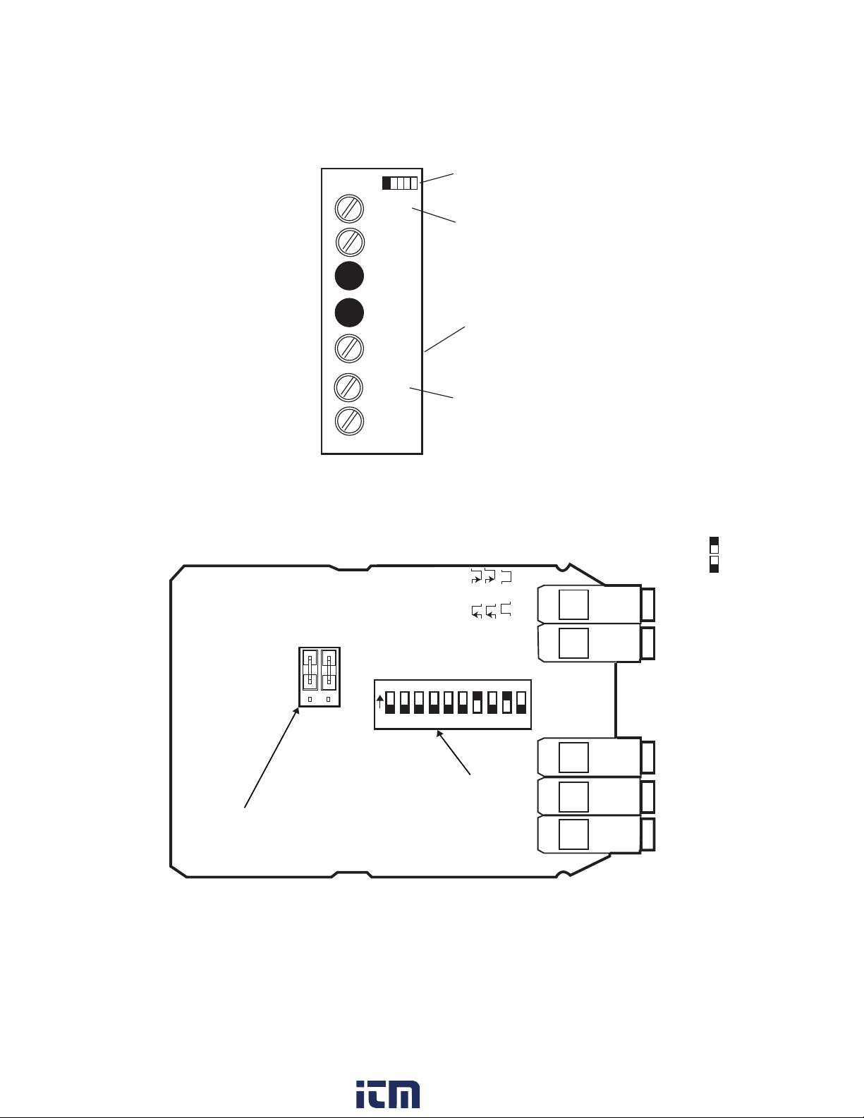
Figure 9. Quadrature /Universal Input Module
Figure 10. Quadrature Input Module Default Settings
A INPUT
USER
INPUT
B INPUT
COMMON
COMMON
INPUT
Secondary Input
or
Quadrature B
Denotes module
position 1at rear
of counter
Display Hold
Freezes
Displayed value
Primary Input
or
Quadrature A
12 3 4 5 67 8 9 10
B Bias Off=Hi On=Lo
B Freq Off=Hi On=Lo
B Off= Sink On= Source
A Freq Off=Hi On=Lo
A Off= Sink On= Source
A Bias Off=Hi On=Lo
B Edge Off= On=
A Edge Off= On=
User pol Off= On=
Quadr Off=X4 On=X1
JP1
JP2
Standard
Count
Quadrature
Count
123
123
Note:To Enable
standard count Mode
move both jumpers
down one pin
SW1
Dip Switch:
Shown in
Quadrature Mode
(Factory Defualt)
Dipswitch Legend = ON
= OFF
www. .com information@itm.com1.800.561.8187

13
Table 3. Quadrature Module DIP Switch and Jumper Settings
JP1/2: Count Mode Selector
Jumpered 1-2 = Quadrature mode**
Jumpered 2-3 = Standard counter mode
SW1: 10 Position DIP Switch
* = Factory Default setting
1 B Channel Bias: OFF = Hi* VLT = 5.0V VUT = 7.0V (+/- 10%)
ON = Low VLT = 1.6V VUT = 3.6V (+/- 10%)
2 B Channel Frequency: OFF = Hi* (low pass filter disabled)
ON = Low (low pass filter enabled)
3 B Channel Sensor: OFF = Sinking* (internal pull-up enabled)
ON = Source (internal pull-down enabled)
4 A Channel Bias: OFF = Hi* VLT = 5.0 V VUT = 7.0V (+/- 10%)
ON = Low VLT = 1.6 V VUT = 3.6V (+/- 10%)
5 A Channel Frequency: OFF = Hi* (low pass filter disabled)
ON = Lo (low pass filter enabled)
6 A Channel Sensor Type: OFF = Sinking* (internal pull-up enabled)
ON = Source (internal pull-down enabled)
7 B Channel Count Edge: OFF = Rising (standard count mode only)
ON = Falling*
8 A Channel Count Edge: OFF = Rising (standard count mode only)
ON = Falling*
9 User Input Polarity: OFF = High/open circuit = Inhibit Count
ON* = Low/closed circuit = Inhibit Count
10 Quadrature Mode: OFF = X4 (quadrature mode only)
ON = X1*
www. .com information@itm.com1.800.561.8187

14
2.6Excitation Module
Figure 11. Wiring Encoder w/ Excitation Supply
12 VDCExcitation Module
The Excitation Module can supply 12 VDCat up to 100 mA for external sensors or en-
coders. This excitation is isolated from the counter internal logic supply. When using
sensors or encoders that do not have a signal return or imply a signal return that is in
common with the supply voltage, a common attachment that ties the excitation supply
to the logic input common may be required. Examples of this appear in figures 8, 8a,
11 and 12.
Figure 12. Wiring Encoder with External Supply
AINPUT
USER
INPUT
BINPUT
COMMON
COMMON
INPUT
PHASE A-WHITE
COMMON
(BLACK)
POSITIVE-RED
PHASE B-GREEN
+
QUADRATURE
INPUT CARD
EXCITAT ION
CARD
QUADRATURE
ENCODER
EXCITATION
ISO+12V
ISOCOM
+
_
__
---
AINPUT
USER
INPUT
BINPUT
COMMON
COMMON
INPUT
CHANNEL A-WHITE
COMMON
(BLACK)
POSITIVE (RED)
CHANNEL B-GREEN
+
QUADRATURE
INPUT CARD
MODEL S.E.
QUADRATURE
ENCODER
+
DENOTES MODULE POSTION 1
AT REAR OF COUNTER
EXTERNAL
POWER
SUPPLY
www. .com information@itm.com1.800.561.8187
15
Figure 13. Excitation Module
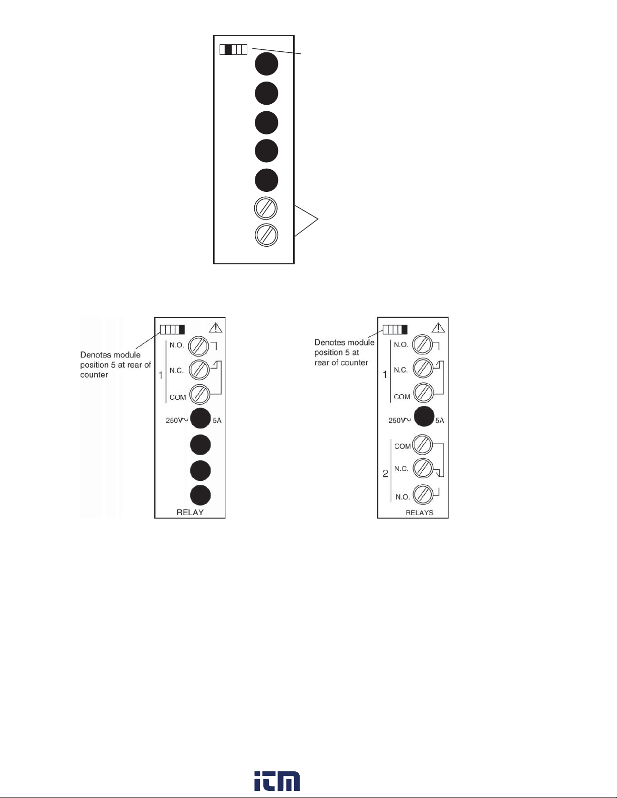
2.7 Single and Dual Relay Modules
Figure 14. Single Relay Figure 15. Dual Relay
The Single and Dual Relay modules can activate circuit loads of up to 5 amps at 250
VAC. A Form C configuration allows use of normally-open (NO) and normally-closed
(NC) circuit action.
Only the output 1 channel is implemented in the single relay module.
EXCITAT ION
ISO+12V
ISOCOM
+
_
__
---
12 VDC, 100 mA max
Denotes module
position 2at rear of
counter
www. .com information@itm.com1.800.561.8187

16
3 Display & Keypad Controls
3.1 Display
Figure 16. Display and Keypad Layout
• 6-digit 0.56” high red LEDdisplay.
• 2 OutputStatusIndicators; “1” and “2.”
• Units Window for supplied label or legend.
• 4-Button keypad with tactile response.
Output Status
Indicators
4 Button Keypad
Numeric & Message Display
Units Window
www. .com information@itm.com1.800.561.8187

17
3.2 Display Error Messages
Table 4. Display Error Messages
Display DescriptionAction Required
PAdErr TheKeypad is disabled or akey is stuck in
theON position
Cycle power tothe
counter, if theerror
remains, return
counter tofactory for
repair.
999999 or
-99999
(Flashing)
Thedisplayed count is too large for the
counter todisplay. Sincetheinternal count
buffer is much larger than thedisplay, the
counter will maintain accuratecount and
control well beyond thedisplay value.
Reset Counter
E1
(Outputs
deactivate, count
stops)
Raw Count Overflow: Thenumber of count
pulses has exceeded thecounter’smaximum
internal value(2,147,483,648 or
-2,147,483,648)
Reset Counter
E2
(Outputs
deactivate, count
stops)
Math Overflow: A large scale factor in
combination with large raw count has
exceeded thecounter'smaximum internal
value(+2,147,483,648 or -2,147,483,648)
Reset Counter
E3
(Outputs
deactivate, count
stops)
Watchdog Fault: Thecounter did not
experiencean orderly power-down.This can
happen by exceedingthemaximum
allowable count speed for asustained period
of time.
Reset Counter
www. .com information@itm.com1.800.561.8187

18
3.3 What the Keys Do in DisplayMode
Key Keypad behavior
Sor T
Allows quick access to all the set points. This
feature can be disabled by using apassword (see
section 4.1).
Hold and
Press S
Access the Programming Menu.
Key Keypad behavior
Press and hold for four seconds to exit the
programming mode.
SorT
The up and down keys navigate through the
available menu functions. The menu ‘wraps
around’ when the bottom or top of the menu is
reached.
1) Enter the current menu or parameter to
view/edit.
2) Write the change to the counter memoryand
move to the next function.
3.4 What the Keys Do in the Programming Mode
RESET
ENTER
ENTER
www. .com information@itm.com1.800.561.8187
19
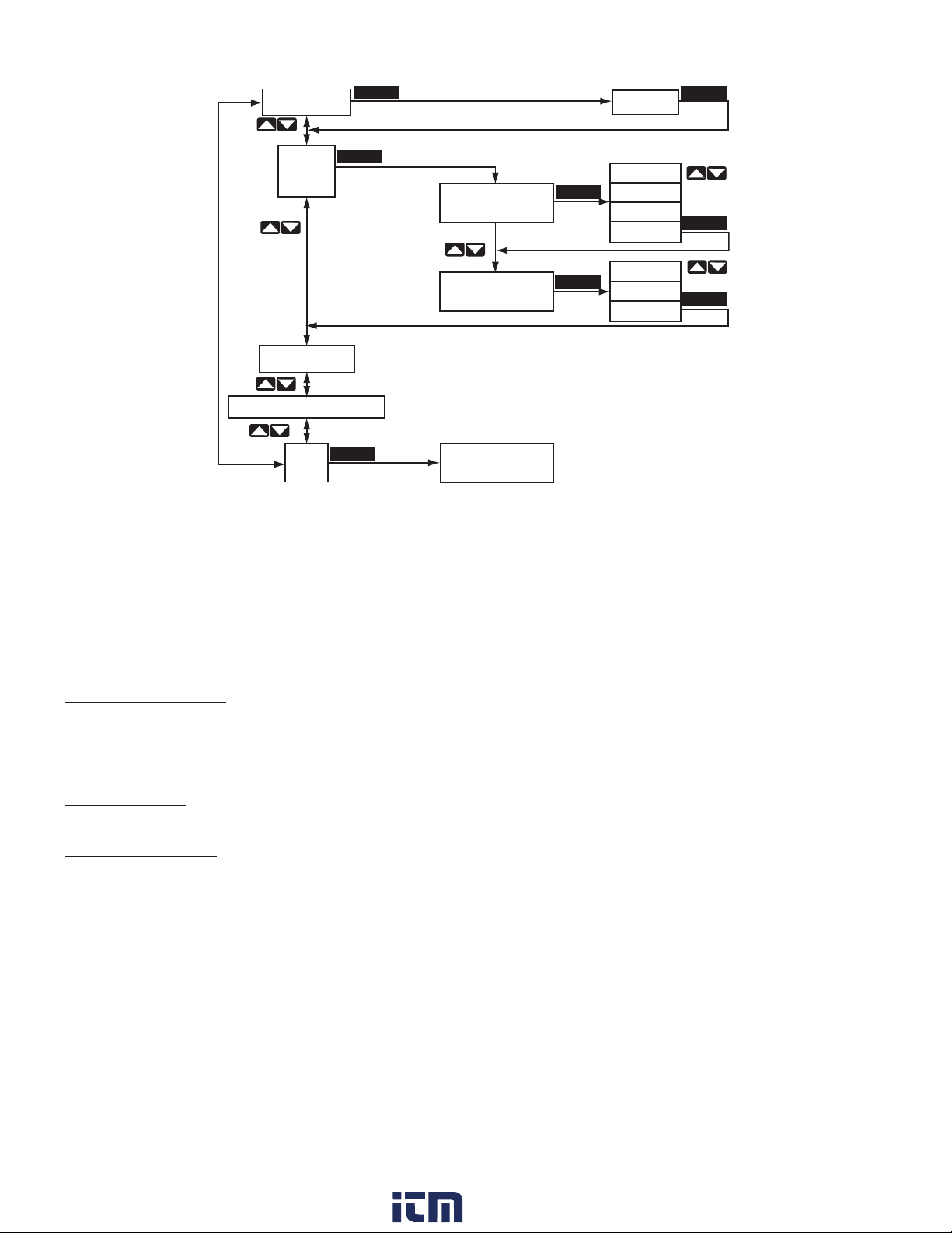
Figure 17. Programming Menu Structure
In the Programming Mode, the S661 will return to Display Mode automatically if a key
is not pressed within 120 seconds (2 minutes). The menu is comprised of three lev-
els: Setup Menu, Function Menu and Option Edit Menu. Figure 17 illustrates the three
levels of the menu system.
Password Entry Entry (Pass) and changing of the password (Chpass) are similar to
editing a numerical parameter. See Numerical Value below. If the
password has been set to a value other than “000,” entry of the prop-
er password is required to access the remainder of the menu.
Setup Menu At the first level of the menu, the arrow keys navigate up or down
through the available Menu selections.
Function Menu The second level of the menu contains the functions or software pa-
rameters that need to be configured for the counter to operate prop-
erly
Option Menu Contains either Choice Lists or Numerical Values for configuring the
counter
Setup Menu Function Menu Option Menu
CHPASS 000
INPUT
SETUP
COUNT SETUP
END
A CHAN UP
B CHAN DOWN
000
up
down
quad
rquad
up
dir
down
other setup menus
Return to
Display Mode
ENTER
ENTER
ENTER
ENTER
ENTER
ENTER
ENTER
ENTER
www. .com information@itm.com1.800.561.8187
Table of contents
Other Simpson Cash Counter manuals


