3
Mounting Position
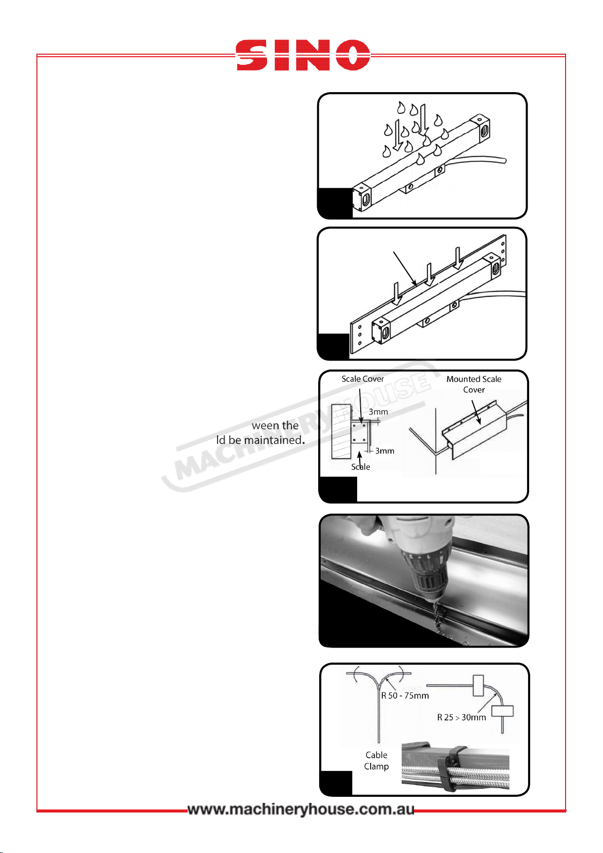
4. The opening of the scale must not be
installed as to be directly exposed to swarf,
oil, water, dust or other foreign products.
(Fig. 3)
Covers provided should be installed.
Fig . 3
Backing Plates
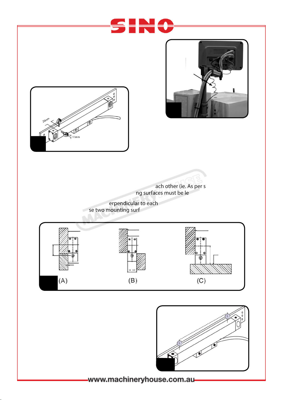
5. In cases where machined at surfaces are
not available, optional backing plates
should be used to provide a at datum for
the installation. (Fig. 4)
Fig. 4
Mounting Plate
Cover Clearance
6. A clearance of at least 3.0mm between the
scale and scale cover should be maintained.
(Fig. 5)
Drilling and Tapping Holes
7. When drilling and tapping the holes be sure
that the drill and tap are square to the cover.
(Fig. 6)
All tapped screw holes must have at least 6
threads to allow the screw to be rmly
secured into the holes. When the screw is
needed to secure a heavy load, the tapped
holes must have at least 8 threads. After
tapping, the holes must be deburred and
cleaned
Fig. 5.
Fig. 6
Securing Cable
8. All cables must be xed, but allow for the
maximum machine travel movements.
Diagram (Fig. 7) recommends the
minimum radius that should be used for
bending the scale cable. Use the cable
clamps supplied to secure the cables to
the display arm. Fig. 7
Instruction Manual for XH-2 (D5200)