Simrad PI TRAWL HYDROPHONE - INSTALLATION REV B User manual

Simrad PI
Catch monitoring system
Trawl hydrophone installation
Installation manual
M A X I M I Z I N G Y O U R P E R F O R M A N C E A T S E A
www.simrad.com


851-164472 / Rev.B
Simrad PI
Catch monitoring system
Trawl hydrophone installation

About this document
Rev Date Written by Checked by Approved by
Rev.B 03.06.05 RBr KRa KRa
Information reorganized
© 2005 Simrad AS. All rights reserved.
ISBN 82-8066-055-0
No part of this work covered by the copyright hereon may be reproduced or otherwise
copied without prior permission from Simrad AS.
The information contained in this document is subject to change without prior notice.
Simrad AS shall not be liable for errors contained herein, or for incidental or
consequential damages in connection with the furnishing, performance, or use of this
document.
The equipment to which this manual applies must only be used for the purpose for
which it was designed. Improper use or maintenance may cause damage to the
equipment or injury to personnel. The user must be familiar with the contents of the
appropriate manuals before attempting to operate or work on the equipment. Simrad AS
disclaims any responsibility for damage or injury caused by improper installation, use
or maintenance of the equipment.
If you require maintenance on your Simrad equipment, contact your local dealer. You
can also contact Simrad using the following e-mail address: fish-support@simrad.com

Installation manual
III
851-164472 / Rev.B
Introduction 1.......................................................
Installation precautions 2..............................................
Considerations 3.....................................................
Pre-installation check-list 8............................................
Optimal location of trawl hydrophones 10..................................
Coverage area, orientation and tilt 13......................................
Mounting arrangement 17...............................................
Dual hydrophone installation 23..........................................
Hydrophone protection 24..............................................
Hydrophone cable 27..................................................
Installation drawings 32................................................

Simrad PI Catch monitoring system / Trawl hydrophone
IV 851-164472 / Rev.B

Installation manual
1
851--164472 / Rev.B
Introduction
The purpose of this document is to provide general guidelines
for the installation of the PI hydrophone for trawling.
Note: If your vessel shall be fitted for purse seine operations, DO NOT
install the hydrophone(s) as explained in this document!
Order numbers
Trawl hydrophone, complete: HYD-205254
Trawl hydrophone, without cable gland: HYD-205826
Topics
→Precautions, page 2
→Considerations, page 3
→Pre-installation checklist, page 8
→Location, page 10
→Coverage area, orientation and tilt, page 13
→Mounting arrangement, page 17
→Dual hydrophones, page 23
→Hydrophone protection, page 24
→Hydrophone cable, page 27
→Installation drawings, page 32

Simrad PI Catch monitoring system / Trawl hydrophone
2851--164472 / Rev.B
Installation precautions
Caution: The following precautions must be observed. Failure to
do so can result in damage to the hydrophone which
may render the PI Trawl hydrophone system
inoperative.
1Observe the maximum allowable torque warning of 5 Nm
when tightening the hydrophone studs.
2Use only M8x35 socket countersunk head screws for
mounting the hydrophone.
3Secure threaded hydrophone hardware with Loctitet270
or the equivalent.
4Do not paint the hydrophone.
5Do not sand-blast, power or steam wash the hydrophone.
6Do not scrape the hydrophone with metal or other hard
objects that may damage the polyurethane sheathing.
7Do not strike the hydrophone.
8Do not expose the hydrophone to harsh chemicals.
9Do not perform hot work in the vicinity of the
hydrophone.
10 Do not lift the hydrophone by its cable.

Installation manual
3
851--164472 / Rev.B
Considerations
Correct installation of PI hydrophone(s) is vital to system
performance. Several variables must be taken into consideration,
the most important of which is the vessel’s construction. This
guide is for use in selecting the best location for the hydrophone
and includes a brief description of areas to be avoided.
Note: Simrad strongly suggests that this information is read
thoroughly, and that the instructions are understood and
followed. Proper hydrophone placement is difficult to achieve,
but essential for correct system operation.
Depth
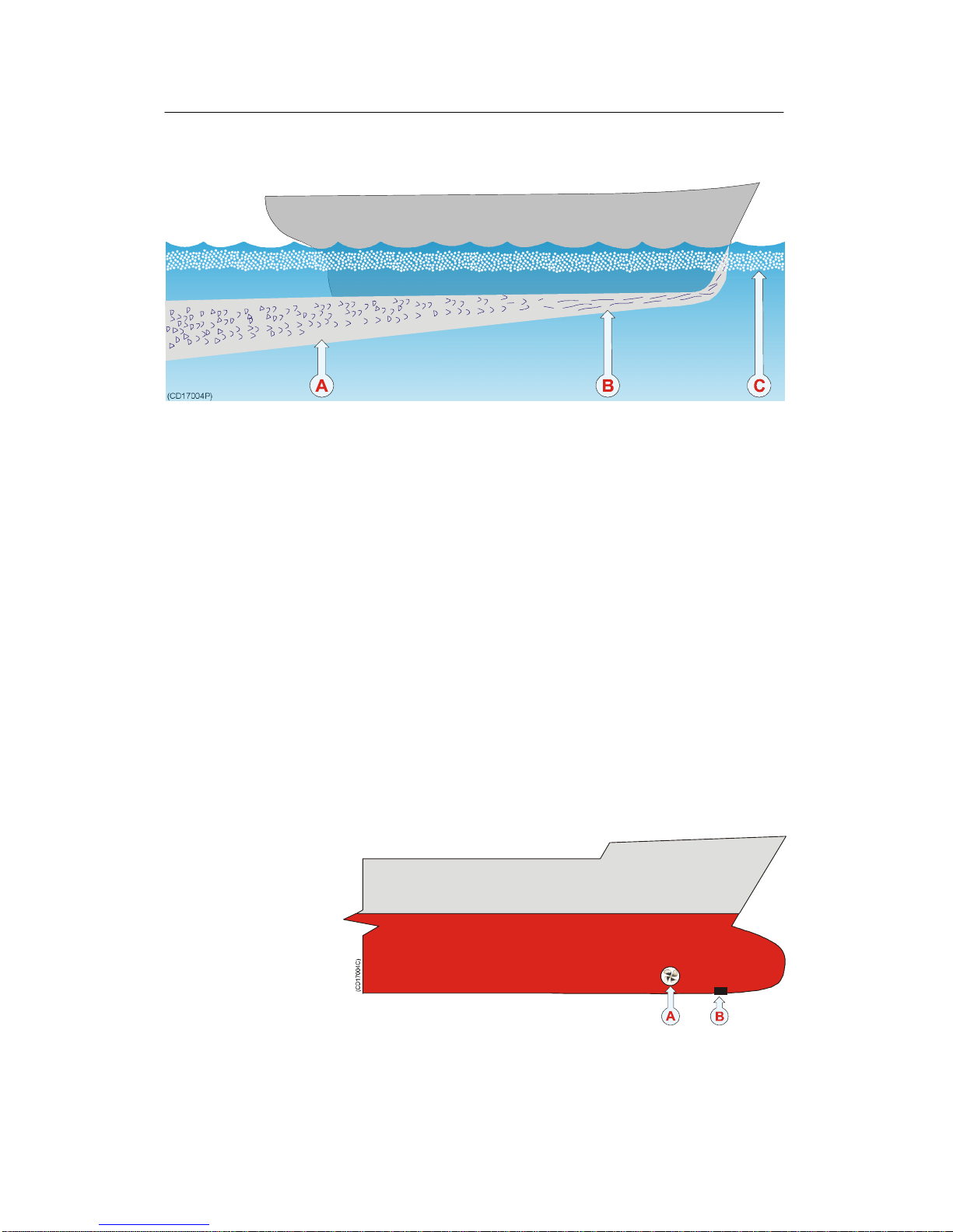
Water just below the sea surface contains a myriad of small air
bubbles created by the turbulence of breaking waves. The first
five to ten metres may be heavily saturated in moderate seas
with the greatest concentration and largest bubbles closest the
surface. Air bubbles disrupt sound waves in water. The degree
to which they absorb and reflect such energy vary, but in some
cases they can block hydrophone reception. It is therefore
recommended to mount the unit as deep as possible.
Pounding danger
When a vessel is in ballast and pitching in heavy seas, it is
important that the hydrophone is not lifted out of the water.
Should a vessel pound so heavily that the hydrophone be
exposed, sound reception will be interrupted and the unit may
be damaged on impact.
The boundary layer
The flow of water in the immediate vicinity of the hull of a
moving vessel is known as a boundary layer. This flow is
responsible for underwater noise that can disturb hydrophone
reception and its thickness is contingent on a vessel’s:
•Hull form
•Size and number of underwater protrusions
•Velocity
•Hull roughness
The boundary layer is thin (laminar flow) near the vessel’s bow
and becomes thicker (turbulent flow) as it moves aft. Laminar
flow is smooth with streamlines approximately parallel to the
hull and contributes relatively little to noise created by flow.
Conversely, turbulent flow is more disorderly and in turn
contributes to a greater extent.

Simrad PI Catch monitoring system / Trawl hydrophone
4851--164472 / Rev.B
Boundary water layers:
(A) = Turbulent flow
(B) = Laminar flow
(C) = Air bubbles in the water
Air bubbles may also be introduced into the boundary layer. If
the vessel’s hull has little flare and is relatively narrow, bubbles
may escape to the sea surface without incident. On the other
hand a wide, flat hull with minimal deadrise is prone to trapping
air bubbles no matter how little flare it has. Regardless of a
vessel’s hull form, hydrophones are generally recommended to
be installed on the forward part of the hull to minimising the
influence of both turbulence and air bubbles.
Bulbous bow
The bulbous bow may be an acceptable hydrophone location.
Should this position be chosen, the foremost part of the bulb is
often best, but also the most susceptible to pounding.
Recommended location of the hydrophone on a bulbous hull:
(A) = Thruster
(B) = Hydrophone location

Installation manual
5
851--164472 / Rev.B
Propeller noise
A vessel’s main propeller is the dominant source of underwater
acoustic noise. When ever possible, hydrophone(s) should be
located as far a way as possible from the main propeller and
never closer than ten meters. Hydrophone(s) should not be
mounted in the direct acoustic path (line-of-sight) of the main
propeller unless absolutely necessary.
The primary cause of propeller noise is cavitation (small
bubbles generated by the partial vacuum created by the blades as
they pass through the water). The resulting underwater acoustic
noise from cavitation is normally weakest on the side of the
vessel were the propeller blades rotate toward the surface and
most pronounced on the side were they rotate toward the
bottom. Most vessels have clock-wise rotating propellers
resulting in their port sides being less effected by cavitation
induced noise than their starboard.
To minimise the negative effect of cavitation noise on
hydrophone performance, installation is generally recommended
as follows:
•Single hydrophone - if only one hydrophone is to be
installed on a vessel with a clock-wise rotating propeller, it
should be located on the port side of the hull.
•Dual hydrophones - if two hydrophones are to be installed,
they should be placed on either side of the vessel’s keel.
When in doubt about the best fore-and-aft location for
hydrophones, they can be placed at different distances from
the bow (for example the port hydrophone can be a little
further aft than the starboard, approximately three to five
meters for a thirty-five meter vessel). When trawling in both
deep and shallow water the hydrophones should also be tilted
differently with respect to each other. The hydrophone that is
closest to the propeller should have the greatest tilt and be
located on the port side of the hull for a vessels with
clock-wise rotating propellers.
Bow/sternthruster noise
Bow and sternthruster operation may severely effect
hydrophone reception. Hydrophone installation closer than four
meters to either is strongly discouraged.

Simrad PI Catch monitoring system / Trawl hydrophone
6851--164472 / Rev.B
When not in operation, bow/sternthruster tunnels create
turbulence and hence underwater noise when a vessel is under
way. Also, as a vessel pitches in heavy weather, thruster tunnels
may fill with air or aerated water which can disturb hydrophone
reception when released. Hydrophone installation should take
into regard the noise and down stream disturbances found
around and aft of thrusters.
Note: Hydrophone installation must take into regard the noise and
down stream disturbances found around and aft of thrusters.
Noise from protruding objects and other sources
The primary sources of underwater disturbance (other than a
vessel’s main propeller and bow/sternthruster) that affect
hydrophone reception are:
•Main or bilge keels
•Zinc anodes
•Cooling elements protruding from the hull
•Equipment such as sonar hydrophones and pitot tubes
•Sea chests
•Overboard discharges
•Dents in the hull
All appendages to the hull, indentations and pipe outlets are
potential sources of underwater noise. They may act as resonant
cavities amplifying noise at certain frequencies, create cavitation
or turbulence. Hydrophones should not be located in the vicinity
of such objects and especially not immediately aft of them.
Minimum distance to sonar and echo sounder
transducers
To avoid interference, PI hydrophone(s) must be installed as far
away as possible from other sources of underwater acoustical
energy such as active sonars and echo sounder transducers.
Hydrophones should be placed at least two meters from such
equipment when ever possible and distances of less than one
meter avoided. Hydrophones installed in close proximity to
underwater acoustical sources should be located as far aft as
possible from them, and most importantly, not be subjected to
direct (frontal) transmission from such equipment.

Installation manual
7
851--164472 / Rev.B
Drop keel
In the event the vessel is equipped with a drop keel, the
hydrophones should be mounted aft of it. The choice between
installing a one, or two hydrophone system should be based on
the same horizontal and vertical coverage requirements for
vessels operating under similar conditions with fixed keels.

Simrad PI Catch monitoring system / Trawl hydrophone
8851--164472 / Rev.B
Pre-installation check-list
Choosing the optimal locations for hydrophones is not always
easy, but decisions made at this phase of the installation process
are critical to future system performance. Determining the best
configuration for a given vessel often involves a compromise
between contradicting requirements.
To aid in this evaluation process Simrad recommends that this
installation manual be read thoroughly and the following check
list completed before deciding on a final installation strategy for
the PI system.
1Hydrophones do not have a direct line-of-sight to the main
propeller and are placed where the vessel’s hull protects
them from underwater acoustic noise as well as possible.
2Hydrophones must always have an unobstructed
line-of-sight to the sensors attached to the gear for the
system to operate properly.
3The distance from the main propeller to the hydrophones
should be greater than ten meters. A separation of less
than ten meters can reduce system range significantly.
4If thrusters are installed, hydrophones should be located at
least four meters from them.
5Avoid locating hydrophones behind thrusters where air
bubbles from their tunnels generated when the vessel
pounds can block sensor signals.
6Hydrophone should not be placed forward of other
underwater acoustic equipment and preferably behind it as
far away as possible, distances of less than one meter
should be avoided.
7There should never be possible sources of underwater
acoustic noise placed in front of hydrophones.
8Hydrophones should be offset twenty degrees from the
vessel’s centre line for normal single boat trawling. This
provides a ten degree overlap and a coverage area of
ninety degrees aft. Refer to the corresponding sections of
this manual for more information.
9If there is any doubt about the best fore-and-aft location,
the port hydrophone can be placed a little farther aft (three
to five meters) in relation to the starboard. Hydrophones
can be tilted at slightly different angles when operating in
both deep and shallow waters. Refer to the corresponding
sections of this manual for more information.

Installation manual
9
851--164472 / Rev.B
10 The hydrophone that is closest to the main propeller
should be located on the port side of the vessel and have
the greatest tilt.
11 If both hydrophone are located equally distant from the
main propeller, but are tilted differently, the starboard
hydrophone should be tilted the most because underwater
acoustic noise is more prevalent on that side of the vessel.
12 Locating hydrophones at the after end of a bulbous bow
can produce good results. Previously installed sonars in
this area that can subject hydrophones to direct signals
will produce interference.
13 Hydrophone can also be mounted in the after end of echo
sounder shoes as long as the minimum required distances
and orientation with regard to other underwater acoustic
equipment is observed.
14 Remember that hydrophones are to be mounted with their
long axis up (in the vertical plane).
15 Hydrophones installed in blisters should be located away
from the vessel’s keel and as deep as possible on the hull.
16 Hydrophones installed in shoes along the vessel’s keel
should be mounted as deeply as possible.
17 Hydrophone cables that are run in conduit along the
outside of the vessels hull should be arranged as to
produce the least amount of underwater acoustic noise as
possible.
18 Blisters and shoes should be as streamlined as possible and
have all of their corners rounded to minimize the
generation of underwater acoustic noise.
19 Conduit used to run hydrophone cables in the interior of a
vessel’s hull should extend well over its water line.
20 If you install both trawl and purse seine hydrophones, do
not confuse the two types. The Trawl hydrophones are
marked with order number 314-205250, while the Purse
seine hydrophones are marked with order number
314-202275.
21 Other well-founded information or experience regarding
hydrophone installation be available should also be
evaluated even though not directly mentioned in these
instructions.

Simrad PI Catch monitoring system / Trawl hydrophone
10 851--164472 / Rev.B
Optimal location of trawl hydrophones
The most influential factors effecting hydrophone reception
common to most vessels are:
•Noise from cavitation generated by the main propeller.
•Air bubbles in the water around the hydrophone which
impede acoustic signals.
•Noise from other acoustic equipment mounted in close
proximity.
If the shipyard or persons responsible for placement and
mounting the hydrophone(s) have knowledge and the proper
experience with installation of similar equipment, it should be
fully exploited when deciding where to locate the hydrophones.
This also holds true for adjusting the degree to which a
hydrophone should be tilted with regard to the both the vessel’s
physical characteristics and fishing method. Proper hydrophone
installation can increase overall system performance more than
any other single factor and therefore it is important that all the
variables involved be understood and taken into account. Often,
individual hydrophone installation requirements contradict one
an other and only an in-depth knowledge of the principles
involved can aid in deciding which should be given priority.
General rules-of-thumb
Although individual vessel vary greatly with regard to physical
construction and fishing methods, the following rules of thumb
apply under most circumstances.
•Hydrophones should be located as far forward as possible,
normally one-third the length of the water-line from the bow.
•If a vessel has a bow thruster, bubbles generated by its tunnel
can block sensor signals. Hydrophones therefore should be
either located forward of bow thrusters or far aft out of the
stream of bubbles found behind them. Vessels equipped with
bulbous bows can mount hydrophones in a specially designed
shoe on the after part of the bulb, forward of the bow
thruster.
•The minimum distance a hydrophone should be located from
the main propeller is ten meters. Systems with hydrophones
mounted closer than this will have reduced range due to
underwater acoustic noise generated by propeller cavitation.
•For trawlers that do not have to take a pursing wire into
consideration, hydrophones can be mounted in specially
constructed blisters offset from the vessel’s keel (preferably

Installation manual
11
851--164472 / Rev.B
1200 mm, but no less than 700 mm) to avoid turbulence. To
also aid in reducing the effects of turbulence, hydrophones
should be installed as deeply as possible (preferably 600 mm,
but not less than 400 mm) from the vessel’s outer hull. When
ever possible, the distance from the keel to the bottom of the
hydrophone blister should not exceed 50 mm which can be
adjusted by countersinking the installation.
•Keel installation of hydrophones is recommended for
combined trawl/purse seining vessels that can not have
blisters projecting from their hulls.
On the starboard side of such vessels a purse seine
hydrophone can be installed together with a trawl
hydrophone.
•Hydrophones should have and unobstructed “view” of the
sensors attached to the gear, but not be located in the
line-of-sight of the main propeller.
•Hydrophones should be located aft of echo sounder
transducers or sonar installations, preferable at a distance of
two meters or more. A proximity of less than one meter
should be avoided and hydrophones should never be subject
to their direct (frontal) transmission.
•Objects protruding from the hull will generate noise, the
areas aft of which should not be used to mount hydrophones.
•Thruster tunnels generate air bubbles which disrupt signals
from the sensors. The areas aft of thruster tunnels or other
sunken areas of the hull should not be used to mount
hydrophones.
•If there is any doubt about the fore-and-aft positions for the
hydrophones, they should be located at different distances
from the bow (three to five meters relative to each other for a
thirty-five meter vessel). The hydrophone that is closest the
main propeller should be located on the port side of the
vessel.
•Hydrophones have a horizontal coverage of approximately
50 degrees. To maximise coverage using two hydrophones
they should be offset preferably 20 degrees outboard. With
this configuration the two hydrophones will overlap each
other by preferably 10 degrees and provide a total system
coverage of 90 degrees.
•Hydrophones have a vertical coverage of approximately 30
degrees. The normal tilt angle is 20 degrees; if the system is
to be used in deep water the hydrophones should be tilted
preferably 30 degrees and in shallow water preferably 10

Simrad PI Catch monitoring system / Trawl hydrophone
12 851--164472 / Rev.B
degrees. To maximise coverage using two hydrophones when
trawling in both deep and shallow water tilt one preferably
15 degrees and the other preferably 30 degrees. The
hydrophone closes to the propeller should be tilted the most
and care should be taken with regard to underwater acoustical
noise.
•Hydrophone cables pass through a vessel’s hull below its
water-line. It is therefore strongly recommended that a length
of conduit be fitted (using approve fastening procedures) to
the interior of hull around the opening made for the
hydrophone’s cable. This conduit should extend vertically
(inside the vessel) over the water-line so that hydrophone
cables can be safely passed through the hull without the
danger of flooding in the event of gland failure. Hydrophones
with steel through-hull fittings installed in this manner can be
replaced without the necessity of dry docking.
•The cable between the hydrophone and the cabinet must be
properly shielded from other potential sources of electrical
interference. A good practice is to run the hydrophone cable
in a steel conduit to the wheel house.
Figure 1 Recommended hydrophone locations
The illustration shows the recommended (A) and the alternative
(B) locations for single hydrophone locations. For a dual
installation, use position (A), and place the port hydrophone
further aft than the starboard. (L) is the total length of the hull
measured at the waterline.

Installation manual
13
851--164472 / Rev.B
Coverage area, orientation and tilt
Once the fore-and-aft placement of the hydrophone is decided, it
is equally important to carefully consider its horizontal and
vertical orientation. Hydrophone orientation can have a large
influence on system performance.
Hydrophones must be configured so that they overlap one an
other in the horizontal plane. Tilt is decided by the actual depth
of the gear. If fishing operations are to be conducted in both
deep and shallow water the hydrophones can be tilted
differently.
Horizontal coverage area
The hydrophone’s beam sensitivity is concentrated within a 50
degrees horizontal and -30 degrees vertical sector. By off-setting
hyprophones by 20 degrees each from the vessel’s centre line an
overlapping coverage area of 20 degrees is provided with a total
coverage area of 90 degrees.
Horizontal coverage area
(A) = Starboard hydrophone
(B) = Port hydrophone
This “rule-of-thumb” is for normal trawling operations. For
pair-trawling or when fishing with Danish seines, the horizontal
position of the hydrophones should be configured with regard to
the operation in question.

Simrad PI Catch monitoring system / Trawl hydrophone
14 851--164472 / Rev.B
Vertical coverage area I
Dual hydrophone installation with hydrophones equally distant
from the bow, but tilted differently.
Typical tilt configuration for operation in both deep and shallow
water when the hydrophones have the same distance from bow.
The hydrophones may be installed in shoes or blisters.
(A) = Using shoes (top view)
(B) = Using blisters (top view)
(C) = Port hydrophone tilted 10 to 20 degrees
(D) = Starboard hydrophone tilted 20 to 35 degrees
(K) = Keel
The hydrophone on the starboard side of the hull should have
the greater tilt of the two, approximately 20 to 35 degrees. The
hydrophone on the port side of the hull should be tilted
approximately 10 to 20 degrees
This manual suits for next models
1
Table of contents
Other Simrad Measuring Instrument manuals

Simrad
Simrad PI50 - REV A User manual

Simrad
Simrad PI44 C User manual

Simrad
Simrad PI PURSE SEINE HYDROPHONE - INSTALLATION REV... User manual

Simrad
Simrad PI30 User manual

Simrad
Simrad PI50 - REV A User manual

Simrad
Simrad ITI TRAWL SYSTEM User manual

Simrad
Simrad PI44 C Instruction Manual

Simrad
Simrad FX80 User manual

Simrad
Simrad PI54 A User manual

Simrad
Simrad PI32 User manual