8 |Installation | M5000 Series User Manual
Fixing options
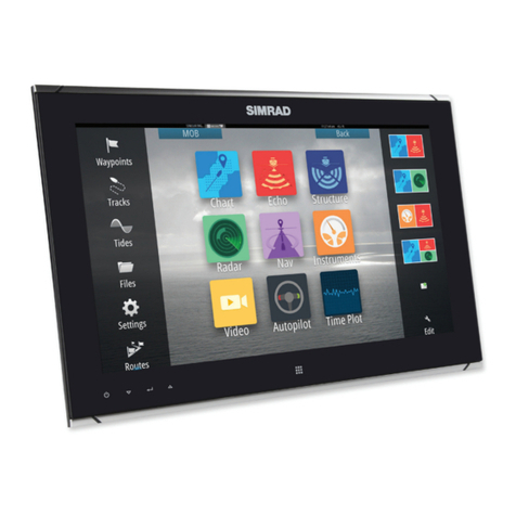
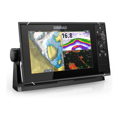
The M5000 series monitors can be dash or bracket mounted (using optional VESA adaptor).
When dash mounting, unit should be tted using the rear mounted dash mount brackets,
and bezel screws from the front. Exclusion of the dash mount bracket will increase strain on
bezel screws and adjacent bezel plastics, and is not recommended.
¼Note: The VESA adaptor xing option is NOT tested against IEC 60945. Monitors that are part
of a type approved system can therefore NOT use the VESA bracket mounting option.
Flush-mounting the display
¼Note: The following guidelines and warnings apply:
Hard materials e.g. GRP, Acrylic, hardwoods
2.3 - 2.5 mm (3/32")
Important drill bit size selection information
Front mount screw recommendations
Soft materials e.g. Plywood
1.9 - 2.3 mm (5/64")
Max 5.5 mm
(0.22”)
1. Fit the supplied M4 machine screws,
washers, and plastic spacers to each of
the four threaded ttings on the back
case of screen. Hand tighten only.
REMOVESHADED AREA
*988-10455-001*
NOTE:
DONOT SCALE
PRINT 1:1
IMPORTANT.Donotuse this template if it has been rescaled
bycopyingor prin ng. If this is not the original, or is a print
fromale, please check the dimension lines below are to
scalebeforeuse.
IMPORTANT.Nepasu liser ce gabarit s’il a été photocopié ou
impriméenformat réduit ou agrandi. Si ce gabarit n’est ni un
originalniune version imprimée d’un chier PDF, veuillez
vérierqu’ilest à l’échelle avant de l’u liser.
IMPORTANTE.nousar la plan lla si haypeligro que la escala
originalexactase ha alterado por copias o procesos de
impresiónimprecisos.Si esto no es el original, o un PDF, veri
carquelas líneas abajo están a la escala antes de usar.
WICHTIG.DiesenVordruck nicht verwenden, wenn er durch
KopierenoderDrucken im Maßstab verändert wurde. Sollte
esnichtdas Original oder ein PDF-Ausdruck sein, müssen
untenstehendeZeilenvor erwendung an den rich gen
Maßstabangepasstwerden.
BELANGRIJK.Gebruikdeze mal niet indien de schaal is veran-
derddoordathet is gecopieerd of gedrukt. Indien deze mal
niethetorigineel of een print van PDF is, controleer dan of de
onderstaandelijnende juiste schaal zijn voordat u ze gebrui-
kt.
IMPORTANTE.Nãou lizeeste gabarito se a escala do mesmo
versidoalterada por cópia ou impressão. Se não for o
originalouuma cópia impressa de um arquivo PDF, verique
aslinhasabaixo, para acertar a escala antes da u lização.
VIKTIGT.Användinte denna mall om den skalats om genom
utskri ellerkopiering.Om de a inte är originalet eller en
utskri frånenPDF, kontrolleraa linjernanedanstämmer
medskalaninnan det används.
IMPORTANTE.Nonu lizzarequesto modello se è stato
ridimensionatocopiandoloo stampandolo. Se questo non è
l’originaleola stampa di un le PDF,vericare se le linee che
seguonodevonoessere dimensionate prima di essere u lizza-
te.
TÄRKEÄÄ.Äläkäytä tätäkaaviota, jos sen mi akaava on
muu unutkopio-idessatai tulostaessa. Jos tämä ei ole alku-
peräinentaiPDF tuloste tarkista rajat mi akaavastaalla
ennenkäy öä.
注意:请尽量不要使用本安装挖孔尺寸模版图的复印件。
如果使用复印件,则在使用之前请确认其比例一定要与原
件大小必须一致。
중요: 복사나 출력으로 크기가 조정 된 경우 이 템플릿을
사용하지 마십시오. 원본이 아니거나 인쇄물이면,
사용하기 전 아래 치수선의 눈금을 확인 해 주십시오.
注:このテンプレートは印刷やコピーによって縮尺が変
わっていることがありますので使用しないで下さい。テ
ンプレートがオリジナルのものでない場合には、下の寸
法線を使って縮尺を確認してください。
ВНИМАНИЕ: Не используйте эту инструкцию, ес
ли она была изменена в размерах при копирова
нии или распечатке. Если вы используете не ор
игинал, а распечатку из файла, убедитесь в соо
тветствии размеров линейки в нижней части и
нструкции с действительными размерами.
Checkdimensions before cutting
12"
300mm
L
C
L
C
192.5mm (7.58")
186.0mm (7.32")
192.5mm (7.58")
186.0mm (7.32")
200.0mm (7.87")
117.5mm (4.63")
111.0mm (4.37")
130.0mm (5.12")130.0mm (5.12")
117.5mm (4.63")
111.0mm (4.37")
200.0mm (7.87")
385.0mm (15.16")
372.0mm (14.65")
400.0mm (15.75")
235.0mm (9.25")
222.0mm (8.74")
260.0mm (10.24")
ZM-16
Marine Monitor
B&G
2. Tape appropriate mounting
template in place on dash, and
ensure cutout lines are level relative
to a reference point on dash.
3. Drill cutout corners with a small
pilot drill bit followed with 13 mm
drill bit. Complete cutout with
jigsaw or similar tool.
¼Note: It is recommended to drill the
screw pilot holes using the drill and
screw guide tool included in the
box.
