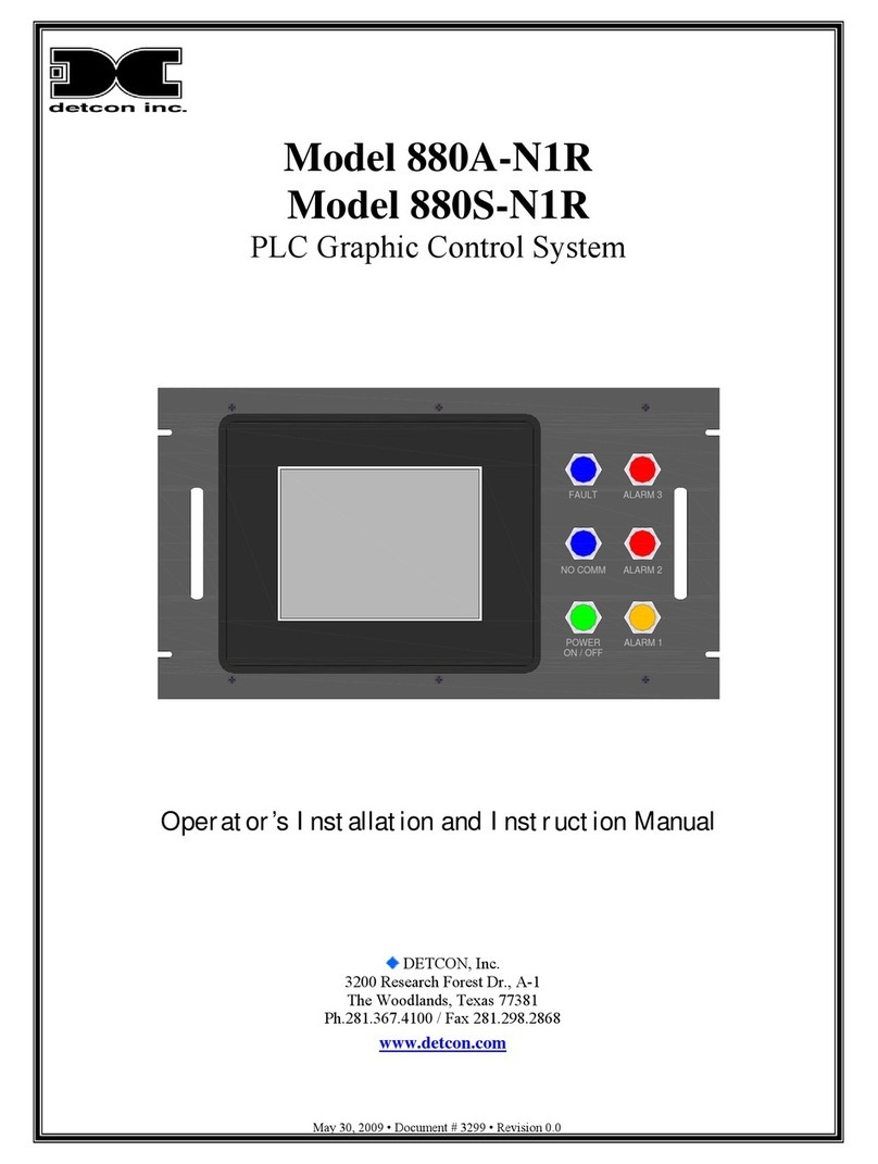
Simu 2200 PRO User manual

2200 PRO2200 PRO
klx
klx
lx
klx
k
lx
klx
k

2200 PRO2200 PRO
1. Introduction..................................................................................................................... 1
2. Definition of Terms........................................................................................................... 2
3. Control Buttons................................................................................................................ 3
4. LCD Display..................................................................................................................... 3
5. Normal Operation........................................................................................................... 4
6. Programming.................................................................................................................. 5
6.1 Sun Function............................................................................................................. 6
6.2 Temperature Function.............................................................................................. 6
6.3 Wind Function.......................................................................................................... 7
6.4 Run Time.................................................................................................................. 8
6.5 Tilt Run Time.............................................................................................................. 8
7. Special Functions........................................................................................................... 9
7.1 Non-Programable Inputs.......................................................................................... 9
7.2 Wind Test.................................................................................................................. 9
7.3 Test Mode................................................................................................................ 10
7.4 Blocking................................................................................................................... 10
7.5 Reset........................................................................................................................ 10
7.6 Total Reset................................................................................................................ 10
8. Trouble Shooting............................................................................................................ 11
8.1 Wind........................................................................................................................ 11
8.2 Sun.......................................................................................................................... 11
8.3 Temperature........................................................................................................... 11
8.4 General Trouble Shooting....................................................................................... 11
9. Wind Table.................................................................................................................... 12
10. Factory Settings........................................................................................................... 13
11. Test Mode Settings....................................................................................................... 13
12. Technical Specifications.............................................................................................. 14
13. Installation Instructions................................................................................................. 14
14. Wiring Diagrams.......................................................................................................... 15

2200 PRO2200 PRO
Welcome to the world of convenience and comfort.
The 2200 line offers convenient built in push buttons and automatic control with a wide array of
advanced sensors including sun, wind, rain, and temperature. The 2200 will automatically respond to
changing light and temperature to maintain your desired comfort level and monitor wind and rain
sensors to provide automatic protection for your window covering. Now you can have the comfort of
automatic shading and temperature control with the peace of mind that comes from automatic
protection from damaging winds or rain.
The advanced 2200 control can provide full digital read outs for light level, wind speed and
temperature. The simple icon based programming and precise digital readouts give you complete
and exacting control of your window covering. No more turning cheap dials or trying to read LED bars
to guess set wind speeds, light levels or exterior conditions.
With simple icon based programming you can set the exact wind speed, temperature or light level you
want your window covering to react to. In addition, full user programable response, delays and run
times give you an unparallel level of control to insure your system responds automatically and precisely
to changing weather conditions.
The advanced features of the 2200 line of controls achieve the maximum benefit from your window
covering to provide comfort, natural lighting control, heating and cooling savings, and protection
against sun fading.
White (Standard)
Surface Mount
Black Textured Faux Walnut Faux Marble
Recessed Mount
White Ivory
1
klx
klx
klx
klx

2200 PRO2200 PRO
1. Delay Time Only used in automatic functions such as the sun. The time length a condition
must be met before the control reacts.
(Min. 1minute - Max. 60 minutes)
2. Run Time The length of time the 2200 will power the motor when it executes a
command. Note, should be set long enough to drive the motor to its limit and
the motor will still stop at its limit.
(Min. 1 second - Max. 240 seconds)
3. Sun Threshold A programmed light level for the 2200 to react at . If the measured value from
The sun sensor exceeds the sun threshold for longer than the delay time, the
2200 will lower the window covering. If the measured value remains below the
threshold for the delay time, the 2200 will raise the window covering.
(Min. 1 klx - Max. 60 klx)
4. Tilt Time A short up pulse given after the run timer ends in the down direction. This pulse
Is given to automatically tilt open some types of venetian blinds after closing.
Unless the 2200 is used with a tilt open blind the tilt time should be set to 0.0
(Min 0.0 seconds - 25.0 seconds)
5. Wind Threshold A programmed wind speed for the 2200 to react at. If the measured value
From the wind sensor exceeds the wind threshold for longer than the delay
time, the 2200 will raise and lock in the up direction the window covering until
the wind Speed stays below the set threshold for longer than the set wind
release time
(Min. 1 mph - Max. 70mph)
6. Wind Release Time The time length the window covering will be locked up after the last measured
wind speed that exceeds the wind threshold.
(Min. 1 minute - Max. 59 minutes)
Unless the 2200 is used with a tilt open blind the tilt time should be set to 0.0
(Min 0.0 seconds - 25.0 seconds)
2

2200 PRO2200 PRO
1 = UP
2 = STOP
3 = DOWN
4 = SET
5 = RESET
6 = AUTOMATIC OPERATION/
MANUAL OPERATION
SELECT
665544
11
22
33
The 2200 display normally shows actual measured weather conditions.
Left* = Sun light in klx
Left* = Temperature in F
Right = Wind Speed in mph
(* Toggle between sun and temperature readings by pressing the up
button (1) for 3 seconds or longer when the unit is in automatic mode.)
1 A sun or hand symbol will be displayed to indicate if the unit is in
automatic or manual mode.
2 A solid arrow indicates the last direction ** the unit switched. A
blinking arrow indicates the unit is active powering the unit in the
indicated direction. Note, the motor will stop if it reaches its limit even if
the unit indicates it is switching power to the motor.
(** If the stop button is depressed before run time ends in the up
direction, the 2200 will still display a solid down arrow to indicate the unit
may still be part way out)
Pressing the set button for a second will cause the programmed
threshold values to be displayed. The 2200 will display the programmed
sun and wind thresholds for 5 seconds and then display the
programmed temperature threshold for 5 seconds. At the end of this
time the unit will return automatically to the measured weather
conditions.
Klx
mph
Klx
mph
1
22
3

2200 PRO2200 PRO
The 2200 can be set in manual or automatic mode to activate the desired control options. The
following table list which functions are active in automatic or manual mode and the level of priority. A
command from a higher priority source will override a lower priority command.
Automatic
Wind
Rain
i1 (up)
i2 (dn)
Temperature
Sun
MODE
PRIORITY
Higher
Lower
Manual
Wind
Rain
i1 (up)
i2 (dn)
Face Plate Switches
Wind - The wind sensor has the highest priority and will override all other functions to protect the window
covering. If the measured wind speed exceeds the programmed wind threshold for longer than the
wind delay, the 2200 will raise and lock the window covering at the up limit. The wind symbol will be
displayed in the bottom bar and the up arrow will blink to indicate and active wind command. Control
of the window covering will be released when the wind speed falls below the wind threshold for longer
than the wind release time.
Rain - The rain sensor has the 2nd highest priority. If a water droplet bridges the gold tracings on the rain
sensor, the 2200 will raise and lock the window covering at the up limit. The rain symbol will be
displayed on the bottom bar and the up arrow will blink to indicate an active rain command. Control
of the 2200 will only be released when the moisture is removed from the rain sensor (due to
evaporation or the water rolling off the sensor. Note, the sensor is slightly heated to reduce the chance
of condensation) Sensitivity and delay times on the rain sensor can be adjusted inside the rain sensor.
See diagram .
I1 - i1 is an up input for external dry contact. As long as the contact from GND to i1 is closed, the i1
symbol will appear in the bottom bar and the up arrow will blink to indicate an active up command.
This input allows external control of the 2200 (examples: fire/smoke alarms, AV systems, home
automation systems, etc...)
I2 - (same as i1 except a down command)
Temperature - (automatic mode only) The 2200 will display the temperature at the location of the
sensor. The temperature function can be turned off (func 0) or on (func 1). If the temperature function is
turned on, and the measured temperature falls below the programmed threshold for longer than 20
seconds, the 2200 will raise the window coving and the temperature symbol will be displayed. When
the measured temperature is above the programmed temperature, the temperature function is
inactive. If the temperature function is turned off, the temperature will have no effect on the control of
the 2200 but the temperature can still be displayed (*see LCD display)
4

2200 PRO2200 PRO
Sun - (automatic mode only) The sun function has the lowest priority. If the measured light level
exceeds the programmed light threshold for longer than the sun down delay time and the 2200 thinks
the window covering is up (solid up arrow) the 2200 will lower the window covering. The sun symbol
will be displayed and the down arrow will blink, indicating an active down command. After the motor
run time has expired the down arrow will turn solid, confirming the 2200 is no longer trying to power the
motor and believes the window covering is part or all of the way down. If the light level falls below the
light threshold for longer than the sun up delay time and the 2200 thinks the window covering is down
(solid down arrow) the 2200 will raise the window covering. The sun symbol will be displayed and the
up arrow will blink, indicating an active up command. After the motor run time has expired the up
arrow will stop blinking, confirming the 2200 is no longer trying to power the motor up and believes the
window covering is all the way up. (Note, stopping the up command with the face plate switches
before the up run time has expired will cause the 2200 to think the window covering “may” still be part
way down and the sun will not cause it to lower again until the unit has received another up command
and been allowed to time out)
Face Plate Switches - (manual mode only) Pressing the up or down face plate switch will cause the
2200 to switch power to the motor in the selected direction. The arrow will blink in the selected
direction. If the switch is held for less than 3 seconds, the 2200 will stop powering the motor as soon as
the butting is released. If the button is held for over 3 seconds, the run time will be engaged and the
2200 will power the motor to the limit in the selected direction and turn off after the run time has
expired.
1 = UP
2 = STOP
3 = DOWN
4 = SET
5 = RESET
6 = AUTOMATIC OPERATION/
MANUAL OPERATION
SELECT
665544
11
22
33
SET
MM
Note, you can always exit the programming mode by pressing the stop button (2) twice. The 2200
will display the threshold values for sun and wind, then temperature and 5 seconds later return to
normal operating mode
To enter programming mode press the set button (4) for 3 seconds
and the programming screen (fig 1) will appear. The SET icon on the
lower left of the screen confirms you are in programming mode. One
of the icons in the lower bar will be blinking. You can move between
the icons by pressing the up (1) or down (3) buttons. Pressing the set
button (4) will let you cycle through the programable values of the
blinking icon.
Fig. 1
5

2200 PRO2200 PRO
SET
MM
6.1 Sun Function - Enter the programming mode by pressing the set
button (4) for 3 seconds. The screen (Fig. 2) to the right will appear. Use
the up (1) or down (3) buttons to select the sun symbol (blinking)
Press the set button (4) and the sun threshold value will appear (Fig 3)
You can adjust this value up or down by pressing the up (1) or down (3)
buttons.
Press the set button (4) and the sun delay down time will appear (Fig. 4).
This is the length of time the measured sun light must be above the
threshold value set above before the 2200 will lower the window
covering. You can adjust this value by pressing the up (1) or down (3)
buttons.
Press the set button (4) and the sun delay up time will appear (Fig. 5).
This is the length of time the measured sun light must be below the
threshold value set above before the 2200 will raise the window
covering. You can adjust this value by pressing the up (1) or down (3)
buttons.
Press the set button (4) to save the programmed sun values and return
to the programming screen (Fig. 2). To adjust other values see following
sections or press the stop button (2) to return to normal operating
mode.
Fig. 2
Klx
SET
SET
min
SET
min
Fig. 3
Fig. 4
Fig. 5
6.2 Temperature Function - Enter the programming mode by pressing
the set button (4) for 3 seconds. The screen (Fig. 6) to the right will
appear. Use the up (1) or down (3) buttons to select the temperature
symbol (blinking).
Press the set button (4) and the temperature function screen will appear
(Fig. 7) or (Fig. 8). FUNC 0 means the temperature function is inactive.
FUNC 1 means the temperature function is active. The function can be
changed by pressing the up (1) or down (3) buttons.
SET
SET
SET
MM
Fig. 6
Fig. 7
Fig. 8
6

SET
F
2200 PRO2200 PRO
Press the set button (4) and the temperature threshold value will appear
(Fig. 9). You can adjust this value bu pressing the up (1) or down (3)
buttons.
Press the set button (4) to save the programmed temperature values
and return to the programming screen (Fig. 6). To adjust other values
see the following sections or press the stop button (2) to return to normal
operating mode.
6.3 Wind Function - Enter the programming mode by pressing the set
button (4) for 3 seconds. The screen (Fig. 10) to the right will appear. Use
the up (1) or down (3) button to select the wind symbol (blinking)
Press the set button (4) and the wind speed threshold will appear
(Fig. 11). You can adjust this value up or down by pressing the up (1) or
down (3) buttons.
SET
MM
Fig. 10
SET
mph
Fig. 11
Fig. 9
Press the set button (4) and the wind delay up time will appear (Fig. 12).
This is the time the wind speed must be above the wind threshold
before the 2200 raises the window covering. Normally this should be
kept low (2 to 3 sec.) You can adjust this value by pressing the up (1) or
down (3) buttons.
Press the set button (4) and the wind release time will appear (Fig. 13).
This is the time that must pass without a wind speed higher than the
wind threshold, before the 2200 will release the window covering. You
can adjust this value by pressing the up (1) or down (3) buttons.
Press the set button (4) and the wind test mode will appear (Fig. 14).
(See wind test section 7.1) Zero means the wind test is inactive. One
means the wind test is active. The mode can be changed by pressing
the up (1) or down (3) buttons.
Press the set button (4) to save the programmed wind values and return
to the programming screen (Fig. 10). To adjust other values see the
following sections or press the stop button (2) to return to normal
operating mode.
SET
sec
Fig. 12
SET
min
Fig. 13
SET
Fig. 14
7

SET
MM
2200 PRO2200 PRO
6.4 Run Time - Enter the programming mode by pressing the set button
(4) for 3 seconds. The screen (Fig. 15) to the right will appear. Use the up
(1) and down (3) buttons to select the run time symbol (blinking).
Press the set button (4) and the run time will appear (Fig. 16). You can
adjust this value up or down by pressing the up (1) or down (3) buttons.
The run time should be set long enough to drive the motor from one
limit to the other.
Press the set button (4) to save the programmed run time and return to
the programming screen (Fig. 15). To adjust other values see the
following sections or press the stop button (2) to return to normal
operating mode.
6.5 Tilt Time - Enter the programming mode by pressing the set button
(4) for 3 seconds. The screen (Fig. 17) to the right will appear. Use the up
(1) or down (3) buttons to select the tilt time symbol (blinking).
Press the set button (4) and the tilt time will appear (Fig. 18). You can
adjust this value up or down by pressing the up (1) or down (3) buttons.
Note: unless you are using a window covering that has louvers that tilt
open on the reverse of direction, the tilt time should be kept at 00.0
Press the set button to save the programmed tilt time and return to the
programming screen (Fig. 17). To adjust other values see the previous
sections or press the stop button (2) to return to normal operation
mode.
Note: At any time in the programming process you can return to
normal operating mode by pressing the stop button (2) twice.
Note: unless you are using a window covering that has louvers that tilt
open on the reverse of direction, the tilt time should be kept at 00.0
SET
MM
MM
SET
MM
sec
Fig. 15
Fig. 16
SET
sec
Fig. 17
Fig. 18
8

2200 PRO2200 PRO
7.1 Non-Programable Inputs
Input i1: For external control up via a continuous pressure, potential free input.
Input i2: For external control down via a continuous pressure, potential free input.
Both inputs are to allow control of the 2200 via external dry contacts from devices such as
clocks, security systems, home automation systems, fire alarm systems, etc...
The inputs require continuous pressure to switch and will power the unit only as long as the
contact remains closed.
Rain: If a rain sensor is connected to the 2200, it will give a continuous up command as long as
there is detectable moisture on the sensor. The rain sensor is not programable via the 2200.
However, the RM-2400 rain sensor does have adjustable settings inside the sensor. These include
four levels of sensitivity to moisture, and three adjustable delay times to react to detected
Moisture. Note: an active rain input is an over ride function on the 2200 and will lock the 2200
In the up direction. If there is a desire to be able to override the rain function, a maintained
off/on switch should be wired in series with the rain sensor and shown on the RM-2400 diagram.
7.2 Wind Test
If the wind test is active (FUNC 1 - see section 6.3), the 2200 will monitor the wind sensor to
confirm it receives a signal from the sensor (at least 1 rotation) every 24 hours. If it does not
receive a signal in 24 hours, the 2200 will assume the sensor has been damaged or the wiring is
broken and go into wind error mode. See Fig. 19 below.
In wind error mode, the 2200 will give a constant up signal. At any time if the 2200 receives a
signal (any rotation) from the wind sensor, it will automatically return to normal operating mode.
If the unit is in wind error mode, you can manually return it to normal operating mode by pressing
the stop button (2). However, you will not be able to return it to automatic mode until the 2200
receives a wind signal.
Fig. 19
9

2200 PRO2200 PRO
7.3 Test Mode - To enter test mode press and hold the stop button (2)
and press the auto/manual button (6) then release both. The test
screen (Fig. 20) will appear and after 2 seconds the unit will go into test
mode (Fig. 21). You can confirm the unit is in test mode by the small ON
displayed in the upper right of the screen. The actual measured weather
conditions will be displayed on the screen. In test mode all functions a
set to very short times to allow the installer to quickly test the unit.
To exit test mode press the stop button. The ON will no longer be
displayed in the upper right of the screen and the 2200 is in normal
operating mode.
7.4 Blocked Mode - You can only enter blocked mode when the 2200
is in automatic mode. To enter blocked mode press the up (1) and
down (3) buttons simultaneously and the blocked screen (Fig. 22) will
appear. In blocked mode the 2200 will give a constant up to the motor
locking the window covering in the up position.
To exit blocked mode press the stop button.
7.5 Reset - To reset the 2200 to the last programmed values press
the reset button (5). Note, on the surface mount 2200 the face
plate will have to be removed as shown (Fig. 23)
7.6 Total Reset - To return the 2200 to factory settings press the set
button (4) for 3 seconds. The 2200 will go into programming mode
with the set icon displayed on the lower left of the screen. Press the reset
button (5). Note, on the surface mount 2200 the face plate will have to
be removed as shown (Fig. 23)
ON
Klx
mph
Fig. 20
Fig. 21
Fig. 22
Fig. 23
10

2200 PRO2200 PRO
8.1 Wind - If no wind speed is indicated when the anemometer is
turning (Fig. 24) or if the wind error screen (Fig. 25) appears when the
anemometer is turning:
-Check the connection and wiring to the anemometer.
-Check the wind sensor with a audible continuity meter. The
meter will beep each time the anemometer turns.
8.2 Sun - If no sun value is displayed (Fig. 26)
-Check wiring to sun sensor. Possible broken connection.
-Test with new sun sensor.
-If sun value reads 60 (Fig. 27)
-Check wiring to sensor. Possible short.
-Test with new sensor.
8.3 Temperature - If no temperature value is displayed (Fig. 28)
-Check wiring to sensor.
-Measured value may exceed range limit.
-Test with new temperature sensor.
Klx
mph
Fig. 24
Fig. 25
Klx
mph
Klx
mph
Fig. 26
Fig. 27
F
mph
Fig. 28
8.4 General Trouble Shooting
-No display on LCD screen
Check 120VAC to terminals L and N
-Motor does not move but can relays click and up and down arrows blink by using face plate
Buttons in manual mode.
Confirm jumper between L and 17
Check fuse
-No reaction from face plate switches in manual mode.
Check for blinking up arrow and blinking icon of higher priority function in lower bar such
as wind, rain, i1 or i2.
-Does not move in or out automatically with the sun light
Confirm 2200 is in automatic mode
Check for blinking up arrow and icon of higher priority such as wind, rain, i1 or i2
2200 PRO2200 PRO
Klx
mph
11

2200 PRO2200 PRO
If unit was just in manual mode, confirm the 2200 does not believe the window coving is
in the correct position (solid arrow in correct direction).
Press the set button for less than one second and make note of the programmed
threshold values that flash on the screen for 3 seconds. Compare the threshold values to
the current measured values. Adjust as needed (see section 6).
MPH Beaufort m/s km/h Observed Wind Effects
<1 0 0-0.2 <1
1-3 1 0.3-1.5 1-5
4-7 2 1.6-3.3 6-11
8-12 3 3.4-5.4 12-19 Wind moves leaves and twigs
13-17 4 5.5-7.9 20-28 Wind moves small branches
18-24 5 8.0-10.7 29-38 Wind moves medium branches
25-31 6 10.8-13.8 39-49 Wind moves large branches
32-38 7 13.9-17.1 50-61 Wind causes trees to sway
39-46 8 17.2-20.7 62-74 Wind blows off some leaves and twigs
47-55 9 20.8-24.4 75-88
56-64 10 24.5-28.4 89-102
65-73 11 28.5-32.6 103-117
>73 12 >32.6 >117
MPH Beaufort m/s km/h Observed Wind Effects
12

2200 PRO2200 PRO
Solar
Threshold 15klx
Delay Time Up 10 minutes
Delay Time Down 2 minutes
Wind
Threshold 18 MPH
Delay Time UP 2 seconds
Delay Release Time 8 minutes
Wind Test 0 (off)
Temperature
Threshold 68 F
Function 0 (off)
Run Time 90 seconds
Tilt Time 00.0 seconds
Solar
Threshold 15klx
Delay Time Up 1 minutes
Delay Time Down 1 minutes
Wind
Threshold 2 MPH
Delay Time UP 2 seconds
Delay Release Time 1 minutes
Wind Test 0 (off)
Temperature
Threshold 68 F
Function 0 (off)
Run Time 10 seconds
Tilt Time 00.0 seconds
13

2200 PRO2200 PRO
Supply Voltage 120 VAC 60 Hz
Fuse 4 Amp Slow Blow
Relay Contacts 250 VAC 10 Amps
Operating Temperature (control) +32 to +120 F (0 to +50 C)
Power Consumption Max. 1.5 VA (Plus power of motor connected)
Dimensions (recessed mount - H x W x D) 4.5” x 6.5” x 2.0” Approx. (Fits in 3 gang box)
Dimensions (Surface mount - H x W x D) 4” x 7.75” x 1.5” Approx.
-The 2200 control is for inside use only. Do not mount in exposed areas.
-The sensors are designed to be mounted outside.
-Install the sensors using the provided brackets.
-Install the sensors with the cables on the down side.
-Wiring to the sensors is low voltage, low current.
18 gage wire can be used up to 100 feet for the sensors
Do not run the sensor wires near EMI sources such as line voltage lines, light ballast, etc
-Mount the wind sensor at the highest point possible near the window covering where wind flow is not
obstructed.
-The sun sensor must be mounted outside and facing the direction the window covering is protecting
against sun.
-Mount the sun sensor away from shadows
-Mount the rain sensor at a angle (provided by the bracket). Mounting the rain sensor flat will cause
poor performance.
-Follow all local and national electrical codes.
-Test the wind sensor to assure it moves the window coving in the correct direction.
14

2200 PRO2200 PRO
M
nGreen(Grou d)
G eenr
l
Neutra
V
Hot (120-60Hz)
Witeh
Red
a
Bl ck
Jumper
2200-WM
WIND SENSOR
2200-LO
SUN SENSOR
OPTIONAL
SECOND
2200-LO
SUN SENSOR
OPTIONALOPTIONAL
120 VAC Connections
Low Voltage Connections
Notice: For installation by a qualified electrician in
accordance with national and local electrical codes.
Terminals 6 through 13 are on Pro versions only
The 2200 control is for inside use only. Do not install in an exposed location.
Terminals 1 thru 13 are low voltage. 18 gage wire is acceptable for
connections up to 100 feet.
Mount the wind sensor high enough and away from obstructions to
allow free wind flow past the sensor.
Mount the sun sensor toward the direction of the sun the window
covering will be protecting from. Make sure the sensor is not shaded
by trees or building structures. Do not mount the sun sensor behind
glass as this will reduce the sensitivity.
Do not connect more than one motor directly to the 2200. For control
of multiple motors by one 2200 use Ri2 and Ri3 group controls.
(See following pages for diagrams)
M
Ground (Green)
Hot Power L1 (Black)
Common N (White)
Motor
Motor Direction (Red/Black)
Note: Connections are only at terminals
120 VAC Connections
Other
Low Voltage Connections
I1 - input for external N.O.
up dry contact.
I2 - input for external N.O.
down dry contact
i1 and i2 require continuous
pressure to switch
For connection to:
Key Switch
Fire Alarm
Clock
Home Automation system
AV System
External up/down switches
i2
i1
TEMPERATURE
SENSOR
2200-TM
++ --
2400-RM
RAIN SENSOR
R
15
2200 PRO2200 PRO
RI2
PP
MM
N
N
CENTRALCENTRAL
N
N
N
N
LL
POWER IN 115VACPOWER IN 115VAC GROUNDGROUND
5AMP MAX5AMP MAX
INDIVIDUAL
SWITCH
INDIVIDUAL
SWITCH
Gre n (Ground)
e
Ne t a
url
o1 HH t ( 20V-60 z)
Jumper
2200-WM
WIND SENSOR
2200-LO
SUN SENSOR
120 VAC Connections
Low Voltage Connections
++ --
2400-RM
RAIN SENSOR
R
M
P
Ground (Green)
Hot Power L1 (Black)
Common N (White)
Motor
Power to Ind. Switch
Motor Direction (Red/Black)
Note: Connections are only at terminals
120 VAC Connections
Notice: For installation by a qualified
electrician in accordance with national
and local electrical codes.
Terminals 6 through 13 are on Pro versions only
The 2200 control is for inside use only.
Do not install in an exposed location.
Terminals 1 thru 13 are low voltage. 18 gage wire
is acceptable for connections up to 100 feet.
Mount the wind sensor high enough and away
from obstructions to allow free wind flow past
the sensor.
Mount the sun sensor toward the direction of the
sun the window covering will be protecting from.
Make sure the sensor is not shaded by trees or
building structures. Do not mount the sun sensor
behind glass as this will reduce the sensitivity.
16

2200 PRO2200 PRO
rG een (Ground)
Neutral
Hot (120 6 Hz
V- 0 )
Jumper
2200-WM
WIND SENSOR
2200-LO
SUN SENSOR
120 VAC Connections
Low Voltage Connections
++ --
2400-RM
RAIN SENSOR
R
M
P
Ground (Green)
Hot Power L1 (Black)
Common N (White)
Motor
Power to Ind. Switch
Motor Direction (Red/Black)
Note: Connections are only at terminals
120 VAC Connections
Notice: For installation by a qualified
electrician in accordance with national
and local electrical codes.
Terminals 6 through 13 are on Pro versions only
The 2200 control is for inside use only.
Do not install in an exposed location.
Terminals 1 thru 13 are low voltage. 18 gage wire
is acceptable for connections up to 100 feet.
Mount the wind sensor high enough and away
from obstructions to allow free wind flow past
the sensor.
Mount the sun sensor toward the direction of the
sun the window covering will be protecting from.
Make sure the sensor is not shaded by trees or
building structures. Do not mount the sun sensor
behind glass as this will reduce the sensitivity.
17
RI3
N
N
CENTRALCENTRAL
N
N
N
N
LL
POWER IN 115VACPOWER IN 115VAC GROUNDGROUND
5AMP MAX5AMP MAX
N
P
M
INDIVIDUAL
SWITCH
P
M
INDIVIDUAL
SWITCH
P
M
INDIVIDUAL
SWITCH

HALCOMASTER 2200/2400 PRO
6 7 8 9 10 11 12 13
DIP 2
DIP 2
DIP 2
30 sec.
120 sec.
0 sec.
S0 S1 S2 S3
S0 S1 S2 S3
1
2
S0 S1 S2 S3
1
1
2
2
DELAYTIME
4 Degree C DIP 4
DIP 3 2S0 S1 S2 S3 - +
6
7
8
2
4
5
3
1
DIP
2
R-
FROSTSECURITY
1 Degree C
Off DIP 4
DIP 3
DIP 3
DIP 4 2
2
1
SENSITIVITY
S0 S1 S2 S3
S0 S1 S2 S3
1
S0 S1 S2 S3
S0 S1 S2 S3
1
1
1
high
very high
slight
normal
Connections
ON
ON
ON
ON
OFF
OFF
ON
2200 PRO2200 PRO
18
2400-RM
Table of contents
Other Simu Control System manuals