Simu 5124491A User manual

F BOÎTIER DÉBRAYAGE EXTÉRIEUR
NOTICE ORIGINALE Lire attentivement cette
notice avant toute utilisation.
S.A.S. au capital de 5 000 000 �- Z.I. Les Giranaux - BP71 - 70103 Arc-Les-Gray CEDEX - FRANCE - RCS VESOUL B 425 650 090 - SIRET 425 650 090 00011 - n°
T.V.A CEE FR 87 425 650 090
5124491A
Par la présente, SIMU déclare que l’appareil est conforme aux exigences essentielles et aux autres dispositions pertinentes de la directive
machine 2006/42/CE.
Une déclaration de conformité est mise à disposition à l’adresse internet www.simu.com
ATTENTION ! Instructions de sécurité importantes. Veuillez lire et suivre attentivement tous les avertissements et toutes les instructions fournis
avec le produit sachant qu’une installation incorrecte peut provoquer des préjudices aux personnes, aux animaux ou aux biens. Les avertissements
fournissent des indications importantes concernant la sécurité, l’installation, l’utilisation et l’entretien. Veuillez conserver les instructions pour les
joindre au dossier technique et pour d’ultérieures consultations.
1.2 CONNEXIONS
1.1 SECURITE GÉNÉRALE
Ce produit a été conçu et réalisé exclusivement pour l’usage indiqué dans cette documentation. Tout usage autre que celui indiqué risque
d’endommager le produit et d’être une source de danger.
Ce produit est conforme à la directive 2006/95/CE
Ne pas faire tomber le produit.
- Les éléments qui composent l’appareil et le montage doivent être conformes aux Directives Européennes suivantes : 2004/108/CE, 2006/95/CE, 2006/42/CE,
89/106/CE, 99/05/CE et leurs modications successives. Pour les pays n’appartenant pas à la CEE, il est conseillé de respecter également les normes citées,
outre les règlements nationaux en vigueur, an de garantir un bon niveau de sécurité.- Le Fabricant de ce produit (par la suite « le Fabricant ») décline toute
responsabilité dérivant d’un usage incorrect ou différent de celui prévu et indiqué dans la présente documentation, de l’inobservation de la bonne technique
de construction des huisseries (portes, portails, etc.) et des déformations pouvant apparaître à l’usage.- Le montage doit être accompli par une personne
compétente (installateur professionnel, conformément à EN12635), dans le respect de la bonne technique et des normes en vigueur.- Avant de commencer le
montage, vérier l’intégrité du produit.- Vérier si l’intervalle de température déclaré est compatible avec le lieu destiné à l’installation de l’automatisation.- Ne
pas installer ce produit dans une atmosphère explosive: la présence de gaz ou de fumées inammables constitue un grave danger pour la sécurité.- Mettre
hors tensions l’installation avant d’accomplir une quelconque intervention. Déconnecter également les batteries tampon éventuellement présentes.- Vérier si
l’installation de mise à la terre est réalisée correctement. Connecter toutes les parties métalliques de la fermeture (portes, portails, etc..) et tous les composants
de l’installation munis de borne de terre.- L’installation doit être équipée de dispositifs de sécurité et de commandes conformes aux normes EN 12978 et
EN12453.- Installer toutes commandes xes en hauteur de façon à ce qu’elles ne représentent pas une source de danger et qu’elles soient éloignées des
parties mobiles. En particulier les commandes à homme présent doivent être visibles directement de la partie guidée et- à moins qu’il n’y ait une clé, se trouver
à 1,5 m minimum de hauteur de façon à être inaccessibles au public.- Fixer, à proximité de l’organe de manoeuvre et de façon permanente, une étiquette sur
le fonctionnement du déverrouillage manuel de l’automatisation.- Utiliser exclusivement des pièces détachées originales pour les opérations d’entretien ou les
réparations. Le Fabricant décline toute responsabilité quant à la sécurité et au bon fonctionnement de l’automatisation en cas d’utilisation de composants d’autres
Fabricants.- Ne modier d’aucune façon les composants de l’automatisation sans l’autorisation expresse du Fabricant.- Informer l’utilisateur de l’installation sur
les risques résiduels éventuels, sur les systèmes de commande appliqués et sur la façon de procéder à l’ouverture manuelle en cas d’urgence: remettre le
manuel d’utilisation à l’utilisateur nal.- Eliminer les matériaux d’emballage (plastique, carton, polystyrène, etc.) conformément aux normes en vigueur. Ne pas
laisser les sachets en plastique et la mousse de polystyrène à la portée des enfants.
ATTENTION ! Pour le branchement sur le secteur, utiliser un câble multipolaire de 4x1,5mm2 de section minimum et du type prévu par les normes
citées précédemment (par exemple, le câble peut être du type H05 VV-F avec une section de 4x1,5mm2). - Immobiliser les conducteurs à l’aide d’une xation
supplémentaire à proximité des bornes (par exemple, à l’aide d’un collier) an de séparer nettement les parties sous tension des parties sous très faible tension
de sécurité.- Pendant l’installation, dénuder le câble d’alimentation an de pouvoir brancher le conducteur de terre sur la borne appropriée en laissant cependant
les conducteurs actifs aussi courts que possibles. Le conducteur de terre doit être le dernier à se tendre en cas de desserrement du dispositif de xation du câble.
ATTENTION ! Les conducteurs à très faible tension de sécurité doivent être physiquement séparés des conducteurs à basse tension.Seul le personnel qualié
(monteur professionnel) doit pouvoir accéder aux parties sous tension.
1.3 DÉMOLITION
L’élimination des matériaux doit être faite conformément aux normes en vigueur. En cas de démolition du produit, il n’existe ni dangers particuliers, ni risques
dérivant du produit en question. En cas de récupération des matériaux, séparez-les par type (parties électriques - cuivre - aluminium - plastique - etc.).
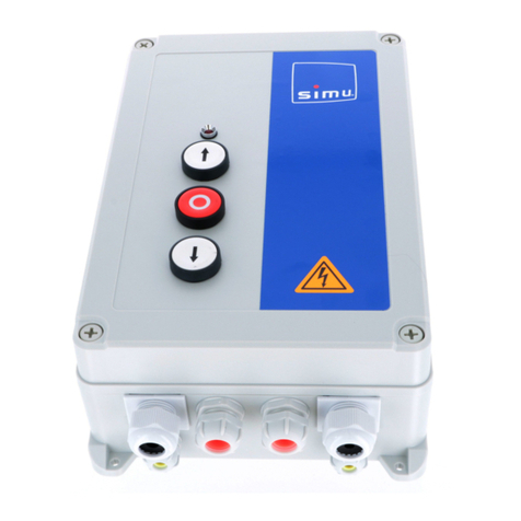
Le boîter sécurisé avec débrayage est conçu pour commander les produits SIMU suivants :
- Gamme moteur Centris SIMU avec câble de débrayage
- Coffret de commande SIMU : SD410, SD 510, RSA, RSA Pro.
Toute utilisation du boîtier sécurisé avec débrayage hors du domaine d'application décrit ci-dessus est interdite. Elle exclurait, comme tout irrespect des
consignes de sécurité et instructions gurant dans cette notice, toute responsabilité et garantie de SIMU.
1.4 DÉMANTÈLEMENT
Si le produit est démontée pour ensuite être remontée sur un autre site, il faut:- Couper l’alimentation et débrancher toute l’installation électrique.- Retirer
l’actionneur de la base de xation.- Démonter tous les composants de l’installation.- Remplacer les composants ne pouvant pas être retirés ou endommagés.
Tout ce qui n’est pas expressément prévu dans le manuel de montage est interdit. Le bon fonctionnement de l’appareil n’est garanti que
si les données indiquées sont respectées. Le Fabricant ne répond pas des dommages provoqués par l’inobservation des indications données
dans ce manuel.En laissant inaltérées les caractéristiques essentielles de l’appareil, l’entreprise se réserve le droit d’apporter à tout moment les
modications qu’elle jugera opportunes pour améliorer le produit du point de vue technique, commercial et de sa construction, sans s’engager à
mettre à jour la présente publication.
Préambule
CONSIGNES DE SÉCURITÉ
1
DOMAINE D’APPLICATION
2
1/6

DESCRIPTIF DU PRODUIT
3
Composition :
N° Désigation Nombre
①Clés 2
②Serrure 1
③Porte boîtier 1
④Fond boîtier 1
⑤Interrupteur 1
⑥Support interrupteur 1
⑦Vis support interrupteur 2
⑧Vis serrure 1
⑨Fil de terre avec cosse à oeil 1
⑩Vis pour l de mise à la terre 2
⑪Poignée de débrayage 1
⑫Tendeur 8x8 leté sur 33mm 1
⑬Serre câble pour tendeur M4 H8.8 1
⑭Ecrou pour tendeur M6x8 2
⑮Cylindre pour tendeur Ø8 percé à Ø6 1
⑯Etiquette d'identication 1
⑰Etiquette d'identication du débrayage 1
①
②
③
④
⑤
⑥⑦
⑧
⑨
⑩
⑪
⑫
⑬
⑭
⑮
⑯
⑰
2/6

INSTALLATION ET RACCORDEMENT
4
Ø17 pour passage câble de
débrayage avec gaîne
Le boîtier peut être monté horizontalement ou verticalement :
Verticalement Horizontalement
trous de Ø5 pour
fixer le boîtier
4.1 Perçage du mur et xation du boîtier
Passage câble
d'alimentation
+ l de terre
44 13
Veuillez respecter les étapes suivantes pour assurer un bon montage :
1 - Tracer la position des trous à l'aide du gabarit échelle (annexe 1) et percer.
2 - Démonter les deux vis du support équipé de l'interrupteur. (repères ⑦)
3 - Passer le câble de débrayage à travers le trou prévu à cet effet (voir photo ci-dessus). S'assurer que la gaîne souple soit bien en
appui sur le fond du boîtier.
4 - Passer le fil de terre et les câbles d'alimentation.
5 - Fixer le boîtier de débrayage au mur avec les éléments de fixation appropriés.
4.2 Raccordement électrique
1 - Brancher le fil de terre sur la vis prévue à cet effet (cf numéro ⑩ sur le fond du boîtier)
2 - Enlever l'interrupteur de son support.
3 - Passer les câbles d'alimentation à travers le support.
3/6

4- Cablage éléctrique.
5
1
2
3
4
220 V 60Hz
230 V 50Hz
120 V 60Hz
❶
❷
❸
3Marron
Noir
Rouge
Bleu
Vert / jaune
1
2
4
PE
Si on veut inverser le sens de montée ou de descente du boîtier, revenir au §4.A et inverser les fils des bornes 1 et 3 de
l'interrupteur.
i
Ne pas desserrer entièrement la vis de terre pour
ne pas perdre la connexion.
i
4.A - Avec moteur
Brancher les fils d'alimentation sur l'interrupteur.
4/6
1 2 3
1 2 3

Moteur central
Coffret d’automatisme
2
3
Rouge
Marron
Vert / jaune
2
3
PE
1 - Mettre en place la poignée
2 - Positionner le tendeur sur le câble.
3 - Positionner le tendeur dans la poignée.
4 - Tendre le câble de débrayage à la main jusqu'à sentir une résistance sans débrayer le moteur.
5 - Serrer la vis M4 du serre câble au couple de 3,2Nm
6 - Apres avoir réalisé 3 débrayages, rattraper le jeu créé à l'aide des écrous du tendeur, toujours sans débrayer le moteur.
7 - Couper le câble de débrayage à 2cm du tendeur.
i
Si nécessaire, il est possible de retendre le câble de débrayage en reproduisant l'étape 6 ci-dessus.
4.3 Montage du débrayage
⑤
⑥⑦
5 - Clipper l'interrupteur sur son support. ATTENTION : ne pas coincer ou endommager les fils.
6 - Visser le support sur le boîtier avec les 2 vis prévues à cet effet (⑦) à un couple de 2 Nm.
2 3
2 3
4.B - Avec coffret de commande
Se reporter à la notice du coffret.
i
Brancher les fils d'alimentation sur l'interrupteur.
5/6

CARACTÉRISTIQUES TECHNIQUES DU PRODUIT
6
Caractéristiques générales
Alimentation secteur 120-230V~ 50/60 Hz
Conditions climatiques d’utilisation +5°C/ +40°C
Indice protection IPX4
Intensité 7A
UTILISATION
5
5.1 Utilisation du rideau électriquement :
1 - Ouvrir le boîtier
2 - Appuyer sur le bouton sens I ou II pour faire monter ou descendre le rideau
3 - Garder le doigt appuyé sur le bouton jusqu'à la position souhaitée
4 - Refermer le boîtier
5.2 Utilisation du rideau manuellement :
1 - Ouvrir le boîtier
2 - Tirer sur la poignée
3 - Manipuler le rideau à la main jusqu'à la position souhaitée tout en maintenant la poignée actionnée
4 - Repousser la poignée
5 - Refermer le boîtier
Pas de maintenance à prévoir.
1
+
+
I
II
i
6/6

GB DECLUTCHING SECURITY BOX
TRANSLATED INSTRUCTION
Read carefully these
instructions before any use.
S.A.S. au capital de 5 000 000 �- Z.I. Les Giranaux - BP71 - 70103 Arc-Les-Gray CEDEX - FRANCE - RCS VESOUL B 425 650 090 - SIRET 425 650 090 00011 - n° T.V.A CEE FR 87 425 650 090
5124491A
Hereby, SIMU, declares that the device is in compliance with the essential requirements and other relevant provisions of the Machinery
Directive 2006/42/CE.
A declaration of conformity is available at www.simu.com
WARNING! Important safety instructions. Carefully read and comply with all the warnings and instructions that come with the product as incorrect
installation can cause injury to people and animals and damage to property. The warnings and instructions give important information regarding
safety, installation, use and maintenance. Keep hold of instructions so that you can attach them to the technical le and keep them handy for future
reference.
GENERAL SAFETY
This product has been designed and built solely for the purpose indicated herein. Uses other than those indicated herein might cause damage to
the product and create a hazard.
- The units making up the machine and its installation must meet the requirements of the following European Directives, where applicable: 2004/108/EC, 2006/95/
EC, 2006/42/EC, 89/106/EC, 99/05/EC and later amendments. For all countries outside the EEC, it is advisable to comply with the standards mentioned, in
addition to any national standards in force, to achieve a good level of safety.
- The Manufacturer of this product (hereinafter referred to as the “Firm”) disclaims all responsibility resulting from improper use or any use other than that for
which the product has been designed, as indicated herein, as well as for failure to apply Good Practice in the construction of entry systems (doors, gates, etc.)
and for deformation that could occur during use.
- Installation must be carried out by qualied personnel (professional installer, according to EN 12635), in compliance with Good Practice and current code.
- Before commencing installation, check the product for damage.
- Make sure the stated temperature range is compatible with the site in which the automated system is due to be installed.
- Do not install this product in an explosive atmosphere: the presence of ammable fumes or gas constitutes a serious safety hazard.
- Disconnect the electricity supply before performing any work on the system. Also disconnect buffer batteries, if any are con-nected.
- Make sure the earth system has been installed correctly: earth all the metal parts belonging to the entry system (doors, gates, etc.) and all parts of the system
featuring an earth terminal.
- Installation must be carried out using safety devices and controls that meet standards EN 12978 and EN 12453.
- Install any xed controls in a position where they will not cause a hazard, away from moving parts. More specically, hold-to-run controls must be positioned
within direct sight of the part being controlled and, unless they are key operated, must be installed at a height of at least 1.5 m and in a place where they cannot
be reached by the public.
- Attach a label near the operating device, in a permanent fashion, with information on how to operate the automated system’s manual release.
- Only use original spare parts for any maintenance or repair work. The Firm disclaims all responsibility for the correct operation and safety of the automated
system if parts from other manufacturers are used.
- Do not make any modications to the automated system’s components unless explicitly authorized by the Firm.
- Instruct the system’s user on what residual risks may be encountered, on the control systems that have been applied and on how to open the system manually
in an emergency. give the user guide to the end user.
- Dispose of packaging materials (plastic, cardboard, polystyrene, etc.) in accordance with the provisions of the laws in force. Keep nylon bags and polystyrene
out of reach of children.
The declutching security box is designed to control the following products SIMU:
- Centris range of motors with declutching cable
- Control boxes SIMU: SD410, SD510, RSA, RSA Pro.
Any use of the declutching security box outside the scope described above is prohibited. It excludes, as any disrespect safety instructions and
instructions in this instruction sheet, any liability and warranty SIMU.
SCRAPPING
Materials must be disposed of in accordance with the regulations in force. There are no particular hazards or risks involved in scrapping the automated system.
For the purpose of recycling, it is best to separate dismantled parts into like materials (electrical parts - copper - aluminium - plastic - etc.).
DISMANTLING
If the automated system is being dismantled in order to be reassembled at another site, you are required to:- Cut off the power and disconnect the whole electrical
system.- Remove the actuator from the base it is mounted on.- Remove all the installation’s components.- See to the replacement of any components that cannot
be removed or happen to be damaged.
Anything that is not explicitly provided for in the installation manual is not allowed. The operator’s proper operation can only be guaranteed if
the information given is complied with. The Firm shall not be answerable for damage caused by failure to comply with the instructions featured
herein.While we will not alter the product’s essential features, the Firm reserves the right, at any time, to make those chan-ges deemed opportune
to improve the product from a technical, design or commercial point of view, and will not be required to update this publication accordingly.
Preamble
SAFETY INSTRUCTIONS
1
APPLICATION DOMAIN
2
WIRING
WARNING! For connection to the mains power supply, use a multicore cable with a cross-sectional area of at least 4x1.5mm2 of the kind provided for by
the regulations mentioned above (by way of example, type H05 VV-F cable can be used with a cross-sectional area of 4x1.5mm2). - Wires must be secured with
additional fastening near the terminals (for example, using cable clamps) in order to keep live parts well separated from safety extra low voltage parts.- During
installation, the power cable must be stripped to allow the earth wire to be connected to the relevant terminal, while leaving the live wires as short as possible.
The earth wire must be the last to be pulled taut in the event the cable’s fastening device comes loose.
WARNING! safety extra low voltage wires must be kept physically separate from low voltage wires.Only qualied personnel (professional installer) should
be allowed to access live parts.
1/6

PRODUCT DESCRIPTION
3
Composition :
N° Desigation
Quantity
①Keys 2
②Lock 1
③Box carries 1
④Bottom box 1
⑤Switch 1
⑥Switch bracket 1
⑦switch bracket screw 2
⑧Lock screw 1
⑨Ground wire with ring terminal 1
⑩Screw for ground wire 2
⑪Declutching lever 1
⑫
Cable adjuster 8x8 threaded on 33mm
1
⑬
Cable mipple for cable adjuster M4 H8.8
1
⑭Cable adjusting nut M6x8 2
⑮Cylinder for cable adjuster 1
⑯Identication label 1
⑰Declutching identication label 1
①
②
③
④
⑤
⑥⑦
⑧
⑨
⑩
⑪
⑫
⑬
⑭
⑮
⑯
⑰
2/6

INSTALLATION AND CONNECTION
4
Ø17 for passing the
declutching cable with
sheath
The box can be mounted horizontally or vertically
vertically horizontally
Hole of Ø5 for fixing
the box
4.1 Wall drilling and xing the box
Pass power cable
+ ground-wire
44 13
Please follow the following steps to ensure proper installation:
1 - Mark the position of the holes using the scale template (Appendix 1) and drill.
2 - Remove the two screws provided with the support of the switch. (cf ⑦)
3 - Pass the declutching cable through the hole (see photo above). Ensure that the flexible sheath is well supported on the bottom of
the box.
4 - Pass the ground wire and power cables.
5 - Set the declutching box to the wall with the appropriate fasteners.
4.2 Electrical connection
1- Connect the ground wire to the screw provided for this purpose (see number ⑩ on the bottom of the box)
2 - Remove the switch from its support.
3 - Place the power cables through the bracket.
3/6

4- Electrical Wiring
5
1
2
3
4
220 V 60Hz
230 V 50Hz
120 V 60Hz
❶
❷
❸
3Braun
Black
Red
Blue
Green/Yellow
1
2
4
PE
If we want to reverse the up and down of the box, return to §4.A and reverse the wire of terminals 1 and 3 of the switch.
i
1 2 3
1 2 3
Do not fully loosen the ground screw to avoid losing
the connection.
i
4.A - With motor
Connect the power cables on the switch
4/6

Central motor
Automation box
2
3
Red
Braun
Green/Yellow
2
3
PE
1 - Position the declutching lever
2 - Position the wire-strainer on the cable.
3 - Position the wire-strainer into the declutching lever
4 - Tighten the declutching cable by hand until resistance is felt without declutching the motor.
5 - Tighten the M4 screws from cable clamp to couple 3,2Nm
6 - Having achieved 3 declutching, take up the play created using the nuts of the wire-strainer, still without declutching the motor.
7 - Cut the declutching cable to 2cm of from the wire-strainer.
i
If necessary, it is possible to tighten the declutching cable reproducing step 6 above.
4.3 Mounting of the declutching
5 - Clip the switch on its bracket. CAUTION: Do not pinch or damage wires.
6 - Screw the bracket to the box with 2 screws provided for this purpose (⑦) to a torque of 2 Nm.
2 3
2 3
4.B - With control boxes
Refer to the instruction sheet of the control box.
i
Connect the power cables on the switch
⑤
⑥⑦
5/6

MAIN FEATURES
6
Main Features
Power sector 120-230V~ 50/60 Hz
Climatic conditions of use +5°C/ +40°C
Protection index IPX4
Intensity 7A
USE
5
5.1 5-1 Use of the curtain electrically
1 - Open the box
2 - Press the direction button I or II for raising or lowering the curtain
3 - Keep your nger on the button until the desired position
4 - Close the box
5.2 Use of the curtain manually
1- Open the box
2 - Pull the declutching lever
3 - Handle the curtain by hand to the desired position while holding the lever pressed
4 - Push thelever
5 - Close the box
No maintenance to be provided
1
+
+
I
II
i
6/6

Perçage du mur echelle 1 :
Drilling of the wall scale 1
97.5
81
140
40
30
50
86
19
Ø17
Ø5
Ø17
Passage câble de
débrayage
Passage declutching
cable
Passage câble d'alimentation + l de terre
Passage power cable + ground wire
ANNEXES 1 / APPENDIX 1


SIMU S.A.S.
Les Giranaux - BP71 - 70103 Arc-Les-Gray CEDEX - FRANCE
Table of contents
Languages:
Other Simu Control System manuals
Popular Control System manuals by other brands

Keystone
Keystone Camp Better quick start guide
Seav
Seav LRX 2035 NEW manual
Whelen Engineering Company
Whelen Engineering Company Core R C399R manual
Fike
Fike CyberCat 50 10-070 Operation & maintenance manual
Nuvation Energy
Nuvation Energy NUV300-BC-12 product manual
SKF
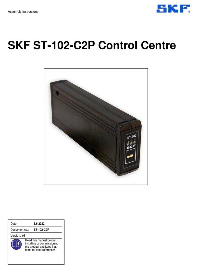
SKF ST-102-C2P Assembly instructions
