Sinclair SDV5-56FA User manual

FULL DC INVERTER SYSTEMS
INSTALLATION MANUAL
INDOOR HIGH STATIC PRESSURE DUCT UNIT SDV5-22-140DHA
COMMERCIAL AIR CONDITIONERS SDV5

Original instructions
IMPORTANT NOTE:
Read this manual carefully before installing or operating
your new air conditioning unit. Make sure to save this
manual for future reference.
1
Comply with local, national and international laws and
regulations.
Read "PRECAUTIONS" carefully before installation.
The following precautions include important safety items.
Strictly follow them.
Keep this manual with the owner's manual in a handy place
for future reference.
1. PRECAUTIONS
The safety precautions listed here are divided into two categories.
Read both carefully.
After completing the installation, ensure that the unit operates
properly during start-up. Instruct the customer on how to operate the
unit and keep it maintained. Also, inform customers that they should
store this installation manual along with the owner's manual for
future reference.
Only qualified service personnel can install, repair, or
service the equipment.
Improper installation, repair, and maintenance may result in
electric shocks, short-circuit, leaks, fire or other damage to
the equipment.
Failure to observe a warning may result in death.
Failure to observe a caution may result in injury or
damage to the equipment.
CONTENTS PAGE
PRECAUTIONS.......................................................................................1
INSTALLATION INFORMATION................................................................2
ATTACHED FITTINGS.............................................................................2
INDOOR UNIT INSTALLATION.................................................................3
INSTALL THE CONNECTING PIPE..........................................................5
CONNECTING THE DRAIN PIPE..............................................................6
WIRING.................................................................................................6
CONTROL OPERATION............................................................................7
TEST OPERATION................................................................................10
Strictly perform installation according to these
installation instructions.
Faulty installation may cause water leaks, electric shocks and
fires.
When installing the unit in a small room, take measures
to keep the refrigerant concentration from exceeding
allowable safety limits in the event of refrigerant leakage.
Contact the place of purchase for more information.
Excessive refrigerant in a closed ambient environment can
lead to oxygen deficiency.
Only use the attached accessories parts and specified
parts for installation.
Otherwise, the set may fall and cause water leaks, electric
shocks and fire.
Install at a strong and firm location that can bear the
set's weight.
If the installation area is not strong enough or installation is
not properly done, the set may fall and cause injury.
The appliance should not be installed in a laundry room.
Before obtaining access to terminals, all supply circuits
must be disconnected.
The appliance must be positioned so that the plug is
accessible.
The enclosure of the appliance must be marked by word
or symbols, including the direction of fluid flow.
For electrical work, follow the national wiring standards,
regulations, and these installation instructions. An
independent circuit and single outlet must be used.
If the electric circuit capacity is insufficient or electrical work
is defective, an electrical fire may result.
Use the specified cable, connect it tightly and clamp the
cable so that no external force will act on the terminal.
If connection or fixing is imperfect, over-heating or a fire at
the connection point may occur.
Wiring routing must be properly arranged so that the
control board cover is fixed properly.
If the control board cover is fixed imperfectly, it may cause
overheating at the connection point of the terminal, a fire, or
electric shocks.
If the supply cord is damaged, it must be replaced by the
manufacturer, its service agent or a similarly qualified
person to avoid a hazard.
A disconnection switch with at least 3mm separation
should be connected in the fixed wiring of all poles.
When connecting the pipes, do not let air get into the
refrigeration cycle.
Otherwise, it will lower capacity and may cause abnormally
high pressure in the refrigeration cycle, an explosion, and
injury.
Do not modify the length of the power supply cord or use
an extension cord, and do not share the single outlet
with other electrical appliances.
Otherwise, it may cause a fire or electric shocks.
Carry out the specified installation work after
considering the possibility of strong winds, typhoons or
earthquakes.
Improper installation work may result in the equipment falling
and causing accidents.
CAUTION
WARNING
WARNING

1
1
2
4
Name of
Accessories
Installation manual
Hook
Hanging arm
Weak electric cable group
1
Drainage pipe
Bolt assembly
Qty
2
(This manual)
Usage
Outline
.
Drainage
1
Copper
Use for pipe connection
of engineering
installation
1
Snapring
Use for fastening the
drainage pipe
Ground the air conditioner.
Do not connect the ground wire to gas or water pipes,
lightning rods, or a telephone ground wire. Incomplete
grounding may result in electric shocks.
Be sure to install an earth leakage breaker.
Failure to install an earth leakage breaker may result in
electric shocks.
Connect the outdoor unit wires, then connect the indoor
unit’s wires.
Do not connect the air conditioner with the power source until
the wiring and piping is completed.
When following the instructions in this installation
manual, install drain piping to ensure proper drainage
and insulate piping to prevent condensation.
Improper drain piping may result in water leaks and property
damage.
Install the indoor and outdoor units, power supply wiring
and connecting wires at least 1 m away from televisions
or radios to prevent image interference ornoise.
Depending on the radio waves, a distance of 1 m may not be
sufficient to eliminate noise.
The appliance is not intended for use by young children
or the elderly without supervision.
Do not install the air conditioner in the following
locations:
Where there is petroleum.
There is salty air surrounding (near the coast). If this
cannot be avoided, choose an anticorrosive model.
Where there is caustic gas (e.g., sulfide, such as near a
hot spring).
Where the voltage vibrates greatly (in factories).
In buses or cabinets.
In kitchens due to oil vapor.
Where there is a strong electromagnetic wave.
Where there are inflammable materials or gas.
Where acid or alkaline liquid evaporates.
Other special conditions.
The appliance should not be installed in a laundry room.
If the refrigerant leaks during installation, ventilate the
area immediately.
Toxic gas may be produced if the refrigerant comes into
contact with fire.
The temperature of the refrigerant circuit will be high, so
please keep the interconnection cable away from the
copper tube.
After completing the installation work, check that the
refrigerant does not leak.
Toxic gas may be produced if the refrigerant leaks into the
room and comes into contact with a source of fire such as a
fan heater, stove or cooker.
CAUTION
To install the unit properly, please read this Installation
Manual.
The air conditioner must beinstalled byqualified personnel.
When installing the indoor unit or its tubing, follow this
manual as strictly as possible.
If the air conditioner is installed on a metal part of the
building, it must be electrically insulated according to the
relevant standards for electrical appliances.
When all the installation work is completed, please turn on
the power only after it has been thoroughly checked.
Notice will not be given regarding any changes to this
manual due to product improvements.
2. INSTALLATION INFORMATION
INSTALLATION ORDER
Select the location;
Install the indoor unit;
Install the outdoor unit;
Install the connecting pipe ;
Connect the drain pipe;
Wiring;
Test operation.
3. ATTACHED FITTINGS
Please check whether all the following fittings have been included.
If there are some spare fittings, please store them carefully.
2
3
Fig.4-4
FOR ORIGINAL CONCRETE BRICKS
Install the hanging hook with expansible bolt into the concrete
deep to 45~50mm to prevent loose.
4.2 Wall Mounting Installation
Fig. 4-5
Hook
D
E
Washer
2.Hangtheindoorunitonthehook.
Tappingscrew
<6mm
Hook
1.Fix the hook with tapping screw onto the wall.(Refer to Fig. 4-8)
Fig. 4-6
Never throw or strike the controller.
Before installation, test the remote controller to
determine its location in a reception range.
Keep the remote controller at least 1 m away
from the nearest TV set or stereo. (It is
necessary to prevent image and noise
interference.)
Do not install the remote controller in direct
sunlight or close to a heating source such as a
stove.
Note that the positive and negative poles are in
the right positions when loading batteries.
CAUTION
Fig.4-1
Fig.4-2
Fig.4-3
WOODEN CONSTRUCTION
NEW CONCRETE BRICKS
Steel bar
Embedding screw bolt
(Pipe hanging and embedding screw bolt)
(Blade shape
insertion)
(Slide insertion)
Roof beam
Hanging screw bolts
Ceiling
Timber over the beam
Place the square timber transversely over the roof beam. Then
install the hanging screw bolts.
Inlaying or embedding the screw bolts.
4. INDOOR UNIT INSTALLATION
NOTE
This manual is subject to changes due to technological
improvement without further notice.
4.1 The units may be mounted vertically providing that
the correct clearances for positioning are maintained.
(Refer to Fig. 4-1 )
Version I
4
Fig.4-7
Hanging arm
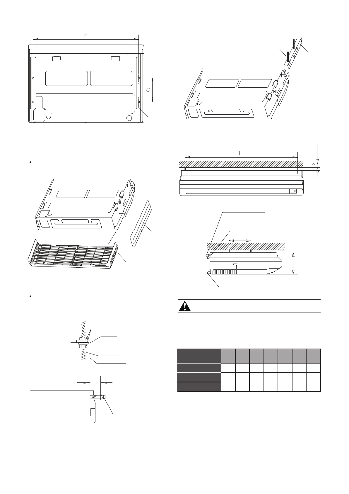
Remove the side board and the grille.(Refer to Fig. 4-8)
(For models 112 and 140, do not remove the grille.)
Fig. 4-8
Side board
Grille
Locate the hanging arm on the hanging screw bolt.
(Refer to Fig. 4-9)
Prepare the mounting bolts on the unit.( Refer to Fig. 4-10)
Screw nut
Washer
Hanging
screw bolt
Hanging arm
Fig.4-9
20~25mm
Hang the unit on the hanging arm by sliding backward. Securely
tighten the mounting bolts on both sides.(Refer to Fig. 4-11)
Mounting bolt(max.40mm)
Fig. 4-10
8~13mm
INDOOR UNIT
4.3 Ceiling Installation
(model 36 ~ 140)
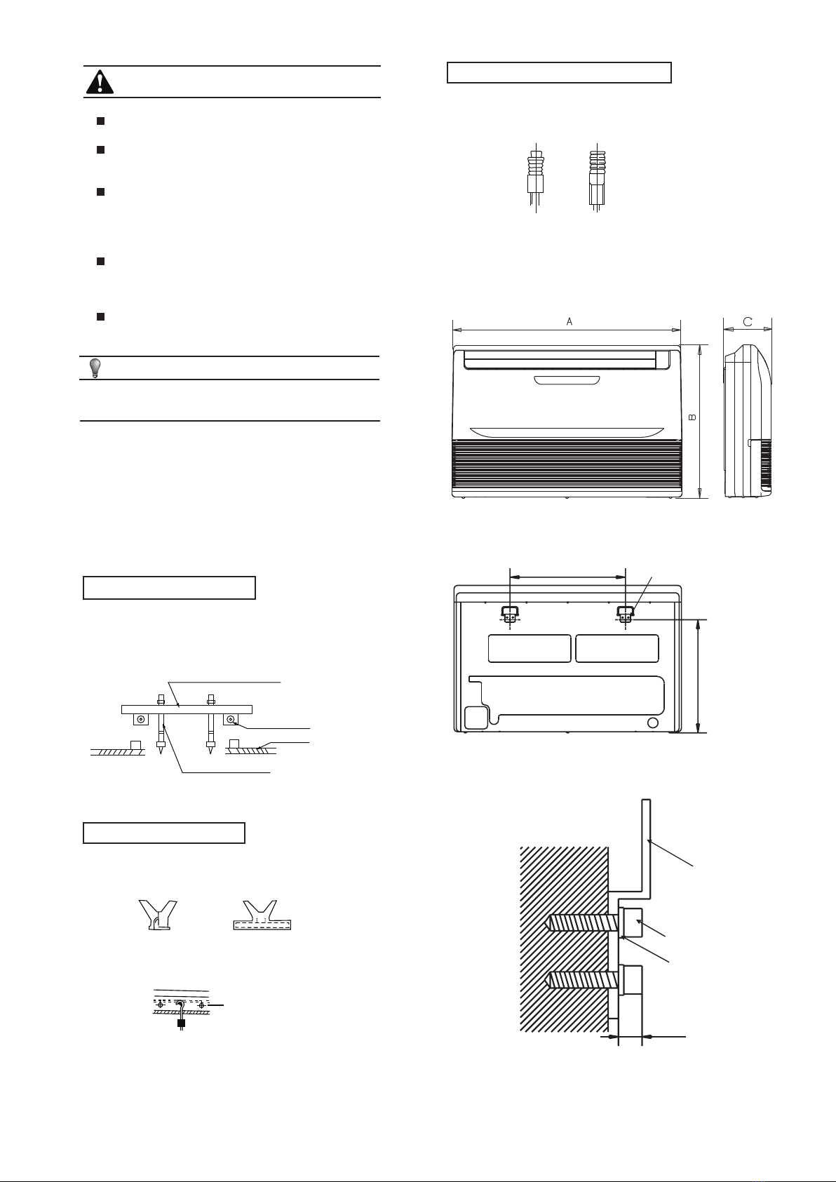
The dimension of the unit (Unit: mm)
4.4
Hanging arm
Mounting bolt
Hanging
screw bolt
D. Connecting point of
refrigerant pipe
(D.gas side)
Drain point
E. Connecting point of
refrigerant pipe
(E. Liquid side)
Fig. 4-11
The figures above are based on model 45 as rated
capacity,which may differ from the unit you purchased.
Table 4-1
20mm
1670 680 244 1070 450 1542 200
MODEL
36~71
80~90
112~140
A B D E F GC
990 660 203 505 506 907 200
1280 660 203 795 506 1195 200
CAUTION
G
C
3.Hang the unit on the hanging arm by sliding backward. Securely
tighten the mounting bolts on both sides.

5
Pipe Materi al
Size(mm)
Copper Pipe for Air Conditio ner
Mode (R22/R 407C) 112~140
36~45 56~90
Pipe Materi al
Size(mm) J(Gas side)
Copper Pipe for Air Conditioner
Mode(R 4 10 A) 36~45 56~140
I(Liquid side) Φ
Φ6.4 Φ9.5 Φ9.5
J(Gas side) Φ
Φ12.7 Φ19.1Φ15.9
Φ12.7
I(Liquid side) Φ6.4 Φ9.5
Φ15.9
5. Install the connecting pipe
Do not let air, dust, or other impurities enter the pipe system
during installation.
The connecting pipe should not be installed until the indoor and
outdoor units have been fixed.
Keep the connecting pipe dry and do not let moisture in during
installation.
The temperature of the refrigerant circuit will be high, so please
keep the interconnection cable away from the copper tube.
CAUTION
Table 4-2
Table 4-3
4.5 Material and size of the piping
5.1 The Procedure of Connecting Pipes
5.1.1 Measure the necessary length of the connecting pipe, and
make it as follows.
1) Connect the indoor unit at first and then the outdoor unit.
a. Bend the tubing in proper way. Do not damage them.
1. Coat the surfaces of the flare pipe and the joint nuts with
frozen oil. Turn by hand 3-4 times and then fasten them with a
wrench.
2. Use two wrenches simultaneously when you connect or
disconnect the pipes.
CAUTION
2) The stop valve of the outdoor unit should be fully closed (as
per the original state). Every time you connect the pipes, first
loosen the nuts at the stop valve. Then connect the flare pipe
(within in 5 minutes). If the nuts have been loosened for a long
time, dust and other impurities may enter the pipe system and
cause a fault. Expel the air out of the pipe with refrigerant
before connecting it.
3) Expel the air (refer to the “Expel The Air”) after connecting
the refrigerant pipe with the indoor unit and the outdoor unit.
Then fasten the nuts at the repair points.
Note for Bendable Pipes.
The bending angle should not exceed 90°.
The bending position is preferably for the bendable pipe. The
larger it is, the better it is.
Do not bend the pipe more than three times.
Bend the connecting pipe of a small wall thickness.
Cut out a desired concave at the bending part of the insulating
pipe.
Then expose the pipe (cover it with tape after bending).
To prevent collapsing or deformation. Bend the pipe at its
widest radius.
Use a bender on low radius pipes.
Use a normal brass pipe.
Use the same insulating materials for the brass pipe. (More than
9 mm thick)
Fig. 5-1
Fig. 5-2
Fig. 5-3
Use frozen oil
Bend the pipe with your thumb
Min-radius 100mm
Make the ends straight
2. Locate the Pipe
1) Drill a hole in the wall (suitable just for the size of the wall
conduit, 90 mm in general), then set on the fittings such as the wall
conduit and its cover.
2) Bind the connecting pipe and the cables together tightly with
binding tape. Do not let air in to avoid leaks due to condensation.
3) Pass the bound connecting pipe through the wall conduit from
outside. Consider the pipe allocation to do no damage to the
tubing.
3. Connect the pipes.
4. Then, open the stem of the stop valves of the outdoor unit to
ensure regular flow in the refrigerant pipe that connects the indoor
and outdoor units.
5. Ensure there are no leaks by checking with a leak detector or
soapy water.
6. Cover the joint of the connecting pipe to the indoor unit with the
soundproof/insulating sheath (fittings), and bind it well with tape to
prevent leaks.
6
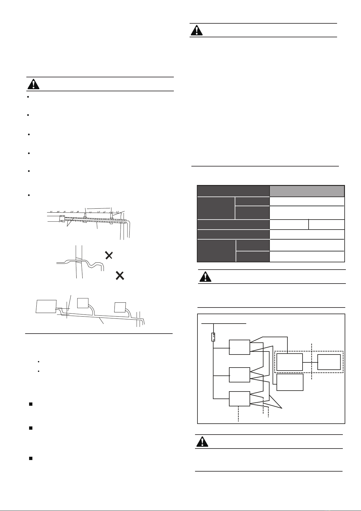
7.1 The specification of power
CAUTION
A disconnection device having an air gap contact separation
in all active conductors should be incorporated in the fixed
wiring according to the National Wiring Regulation.
CENTRAL CONTR OL
MONITOR(CCM)
IN DOOR UNIT
OUTDO OR UNI T
COMP UTER
IN DOOR UNIT
IN DOOR UNIT
The shield twisted-pair wire
Power (220-240V~ 50Hz/220-240V~ 50/60Hz)
CAUTION
The reserved function is indicated in broken line table,users
can select it when necessary
Fig. 7-1
Table 7-1
TYPE (W) 3600-14000W
1-PHASE
Power
Phase
Frequency
& volt
Circuit breaker/fuse (a)
Indoor/outdoor
connecting wire
(mm2)
Ground
wiring(mm2)
Weak electric
signal
5/3 5/5
1.0
0.75
220-240V~ 50Hz
220-240V~ 50/60Hz
Indoor unit power wiring(mm2) 1.0
CAUTION
The drain pipe and connections of the indoor unit must be heat
insulated, or it attracts condensation.
A hard PVC binder must be used to connect the pipes. Ensure
there are no leaks.
6. CONNECTING THE DRAIN PIPE
6.1 Install the drainpipe of the indoor unit
The outlet has a PTI screw bread. Use sealing materials and a
pipe sheath (fitting) when connecting PVC pipes.
6.2 Drainage test
Check whether the drainpipe is unhindered.
Newly built house should be tested before decorating
the ceiling.
When connecting to the indoor unit, do not put pressure on the
side of the indoor unit’s pipes.
Avoid winding when the declivity of the drain pipe in the
downwards direction is over 1/100.
The total length of the drain pipe when pulled out must not
exceed 20 m. When the pipe is too long, install a prop stand to
prevent winding.
Refer to the Fig.8-1 for the installing the pipes.
1.5m~2m
Insulating
material
Downward declivity
lower than 1/100
Bend
S shape
VP 30
Downward declivity
lower than 1/100
Put as deep as possible
(about 10cm)
Fig. 6-1
7. WIRING
Specified power cables should be used. Do not apply any
pressure on the terminals that will be connected.
Improper connection may cause a fire.
Grounding must be properly done.
The grounding wire should be away from gas pipes, water
pipes, telephones, lightning rods or other grounding wires.
Improper grounding may cause electric shocks.
Wiring must be done by professionals. Use a separate
circuit according to national regulations.
If the wiring capacity is not enough, electric shocks or fire may
occur.
CAUTION
1. Be sure to Install Current Leakage Protection Switch, Or
electric shock may occur.
2. Power cord is to be selected according to national regula-
tions.
3. An all-pole disconnection device which has at least a 3 mm
separation distance between all poles and a residual current
device (RCD) with a rating above 10 mA must be incorporated
in the fixed wiring according to national regulations.
4. Select and connect outdoor unit power cords according to the
outdoor unit installation manual.
5. Wiring should be away from high temperature components,
or the insulation layer of the wires may melt.
6. Use a wire clamp to fix the wires and terminal block after
connection.
7. Control wire should be wrapped together with heat insulated
refrigerant pipes.
8. Connect the indoor unit to power only after the refrigerant
has been vacuumed.
9. Don’t connect the power wire to the signal wire connection
end.

7
8.3 DISPLAY BOARD
8. CONTROL OPERATION
Base on different purposes to setting the switch cords on PC panel
of indoor electrical control box. Once finish the setting, please cut off
the main power, and then input power again, otherwise, setting
function could not work.
8.1 Horsepower set
Horsepower code
0
1
2
3
4
5
6
7
8
9
A
B
C
D
E
F
ENC1
POWER_S
8.2 Network address set
ENC1
1
2
3
4
6
5
7
2800 W
Code
Switch For setting the cooling output
Capacity
Note: No one
are permitted to
alter the cooling
output which be
set before
shipping from
factory, except
licensed
maintain
personnel.
Table: 8-1
8000 W
7100 W
5600 W
4500 W
3600 W
9000 W
A
B
12500 W
14000 W
11200 W
10000 W
8
9
0 2200 W
7.2 Indoor/outdoor unit signal wire
Connect the wire according to their numbers.
Incorrect connection may cause an error.
7.3 Wiring connection
Seal the wiring connection with the insulation material, or the
condensation will be caused.
7.4 Panel Wiring
7.5 Terminal Board Diagram
Please refer to the indoor unit wiring diagram.
Note: The air conditioners can connect to the Central Control
Monitor (CCM). Before use, ensure the wiring is correct and
set the system address and network address for the indoor
units.
Connect the Swing Motor terminal block according to the
Panel Installation Manual.
To indoor power
220-240V~50Hz
(208-240V~50/60Hz)
Signal-phase power supply model
To indoor power
220-240V~50Hz
(220-240V~50/60Hz)
LN
Fig. 7-2
Display
board
Wire
controller
Use the shielded twisted-pair
wire, and connect the shielded
To wire controller
The reserved wire control
function is indicated in the
broken line table. The user
can purchase the wire controller
if necessary.
TO CCM
COMM.BUS
TO INDOOR&OUTDOOR
COMM.BUS
layer to (E)
The system comprises 64 units (0-63) Each has a unique
address. A repeated address in the same system will cause
an error.
Switch off the power before changing a setting or an error
may occur.
CAUTION
1) The network address is set based on communication
between the indoor and outdoor units. The address is the same
as the indoor address, and there is no need to set them
separately.
2) The central control of indoor units can be done on an
outdoor unit. There is no need to control indoor unit separately.
For details, please refer to V4+ outdoor unit manual.
3) For previous control of the indoor units, the network can be
set by connecting (X, Y, E) terminals. There is no need to set
the network address. The network can also be set by outer
network module and main board (CN20).
DEFROST/
FAN LIGHT ALARM LIGHT
OPERATION
LIGHT
TIMER LIGHT INFO BUTTON
a
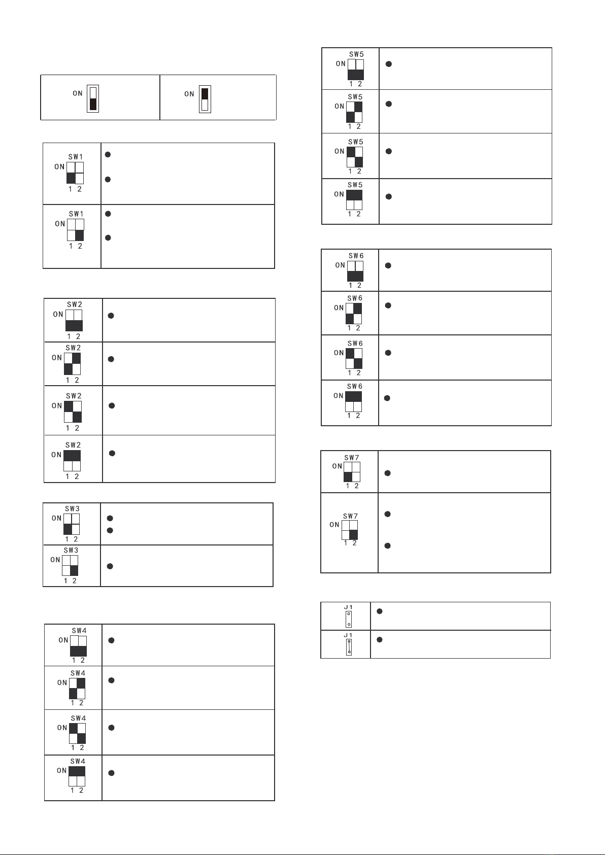
means 0 means 1
0/1 definition of each dial code switch:
0 means cooling mode temperature
compensation is 0°C (default)
1 means cooling mode temperature
compensation is 2°C
0 means EXV positions 96 (steps)
in standby in heat mode (default)
1 means EXV positions 72 (steps)
in standby in heat mode
SW1 definition
00 means external static pressure
mode 1 (default)
01 means external static pressure
mode 2
10 means external static pressure
mode 3
11 means external static pressure
mode 4
SW2 definition
0 means no action (default)
1 means clear indoor unit address
Reserved (defaults 0)
SW3 definition
00 means the time of stopping
TERMAL fan is 4 mintue (default)
01 means the time of stopping
TERMAL fan is 8 mintue
SW4 definition
10 means the time of stopping
TERMAL fan is 12 mintue
11 means the time of stopping
TERMAL fan is 16 mintue
00 means shutting down the unit to
"stop cold air" at 15℃(default)
01 means shutting down the unit to
"stop cold air" at 20℃
SW5 definition
10 means shutting down the unit to
"stop cold air" at 24℃
11 means shutting down the unit to
"stop cold air" at 26℃
00 means temp. compensation value
is 6°C under heat mode (default)
01 means temp. compensation value
is 2°C under heat mode
SW6 definition
10 means temp. compensation value
is 4°C under heat mode
11 means temp. compensation value
is 0°C under heat mode (follow me)
J1 definition
SW7 definition
Reserved (defaults 0)
Without jumper “J1” for auto restart
function
With jumper “J1” for manual restart
function
0 means
low power setting
(1.8kW - 25.2kW) (default)
1 means
high power setting
(28kW - 112kW)
8
8.4 Main board Code designation

Error Code List
No address when first time power on
M-Home not matched error(Reserved)
Mode conflict
Error of indoor temp. sensor (T1)
Error of pipe temp. sensor (T2)
Error of pipe temp. sensor (T2B)
EEPROM error
Outdoor unit error
Water level alarm
FE
H0
E0
E7
Ed
EE
E2
E3
E4
E1
DC FAN errorE6
Error of electronic expansion valve
E5 Reserved
Eb
Communication error of indoor and
outdoor units
9
9. TEST OPERATION
Testing must be carried out after installation is completed.
Please confirm the following points before the test:
2
1
According to the user's requirements, install the remote
controller frame where the remote controller's signal can
smoothly reach the indoor unit.
Test operation
4
3
The indoor unit and outdoor unit are installed properly.
The tubing and wiring have been correctly completed.
The refrigerant pipe system has been checked for leaks.
Drainage is unimpeded.
The heating insulation works well.
The ground wiring is connected correctly.
The length of the tubing and the added stow capacity of
the refrigerant have been recorded.
The power voltage fits the rated voltage of the air
conditioner.
There is no obstacle at the outlet and inlet of the outdoor
and indoor units.
The gas side and liquid side stop valves are both open.
The air conditioner is pre-heated by turning on the power.
Set the air conditioner in "COOLING" mode with the remote
controller, and check the following points. If there is an error,
please resolve it according to the chapter "Troubleshooting" in
the "Owner's Manual".
1) The indoor unit
a. Whether the switch on the remote controller is working
well.
b. Whether the buttons on the remote controller is working
well.
c. Whether the air flow louver moves normally.
d. Whether the room temperature is adjusted properly.
e. Whether the indicator lights normally.
f. Whether the temporary buttons works well.
g. Whether drainage is normal.
h. Whether there is vibration or abnormal noise during
operation.
I. Whether the air conditioner heats well in
HEATING/COOLING mode.
2) The outdoor unit
a. Whether there is vibration or abnormal noise during
operation.
b. Whether the generated wind, noise, or condensation
produced by the air conditioner affect your neighbors.
c. Whether any refrigerant leaks.
CAUTION
A protection feature prevents the air conditioner from being
activated for approximately 3 minutes when it restarts after
shut off.
NOTE CONCERNING PROTECTION OF
ENVIRONMENT
This product must not be disposed of via normal household waste after its service life, but must be
taken to a collection station for the recycling of electrical and electronic devices. The symbol on the
product, the operating instructions or the packaging indicate such disposal procedures. The materials
are recyclable in accordance with their respective symbols. By means of re-use, material recycling or
any other form of recycling old appliances you are making an important contribution to the protection
of our environment. Please ask your local council where your nearest disposal station is located.
INFORMATION CONCERNING USED REFRIGERANT
MEDIUM
This unit is containing fluorinated gases included in the Kyoto protocol. The maintenance and the liquidation must
be carried out by qualified personnel.
Type of refrigerant: R410A
The composition of the cooling medium R410A: (50% HFC-32, 50% HFC-125)
The quantity of the refrigerant: please see the unit label.
The value GWP: 2088 (1 kg R410A = 2,088 t CO2 eq)
GWP = Global Warming Potential
In case of quality problem or other please contact your local supplier or authorized service center.
Emergency number: 112
PRODUCER
SINCLAIR CORPORATION Ltd.
1-4 Argyll St.
London W1F 7LD
Great Britain
www.sinclair-world.com
This product was manufactured in China (Made in China).
REPRESENTATIVE
SINCLAIR Global Group s.r.o.
Purkynova 45
612 00 Brno
Czech Republic
TECHNICAL SUPPORT
SINCLAIR Global Group s.r.o.
Purkynova 45
612 00 Brno
Czech Republic
Tel.: +420 800 100 285
Fax: +420 541 590 124
www.sinclair-solutions.com
info@sinclair-solutions.com
This manual suits for next models
7
Table of contents
Other Sinclair Inverter manuals

Sinclair
Sinclair CCM04 User manual

Sinclair
Sinclair SDV6-DM Series Operating manual

Sinclair
Sinclair SDV6-C Series Operating manual

Sinclair
Sinclair SDV5 Series Operating instructions

Sinclair
Sinclair SDV6 User manual

Sinclair
Sinclair SDV4-140HB3P User manual

Sinclair
Sinclair SDV5 Series User manual

Sinclair
Sinclair SDV6 SCC-61 Operating manual

Sinclair
Sinclair SDV5-MOD User manual

Sinclair
Sinclair SDV5 Series Guide


