Siqura HSD626EXP User manual

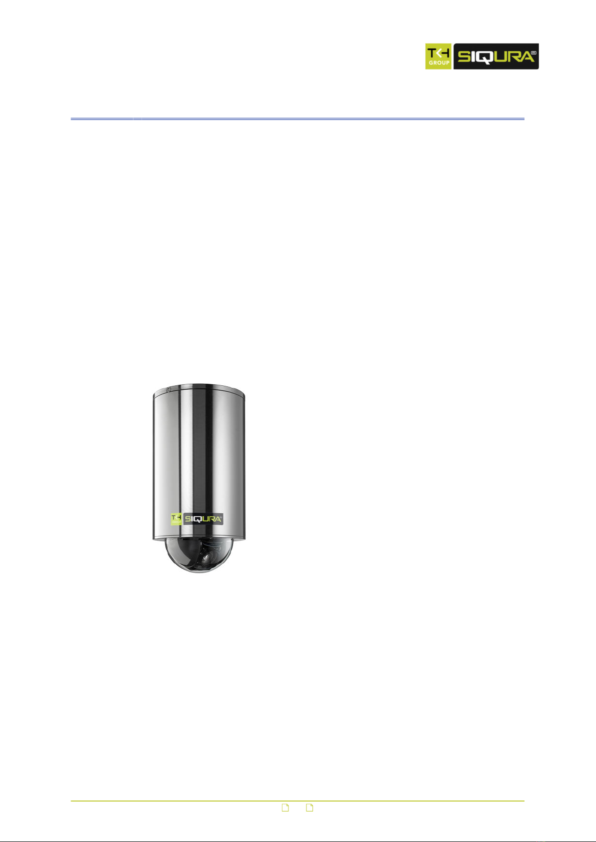
HSD626EXP
Explosion-protected IP PTZ dome camera
Installation Manual

Note: To ensure proper operation, please read this manual thoroughly before using the
product and retain the information for future reference.
Copyright © 2015 Siqura B.V.
All rights reserved.
HSD626EXP 4.14
Installation Manual v1.0 (150110-1)
AIT55
Nothing from this publication may be copied, translated, reproduced, and/or published by
means of printing, photocopying, or by any other means without the prior written permission
of Siqura.
Siqura reserves the right to modify specifications stated in this manual.
Brand names
Any brand names mentioned in this manual are registered trademarks of their respective
owners.
Liability
Siqura accepts no liability for claims from third parties arising from improper use other than
that stated in this manual.
Although considerable care has been taken to ensure a correct and suitably comprehensive
description of all relevant product components, this manual may nonetheless contain errors
and inaccuracies. We invite you to offer your suggestions and comments by email via
[email protected]. Your feedback will help us to further improve our documentation.
How to contact us
If you have any comments or queries concerning any aspect related to the product, do not
hesitate to contact:
Siqura B.V.
Zuidelijk Halfrond 4
2801 DD Gouda
The Netherlands
General : +31 182 592 333
Fax : +31 182 592 123
E-mail : [email protected]
WWW : www.siqura.com
2

Contents
1 About this manual ..................................................................................... 4
2 Safety and compliance .............................................................................. 6
2.1 Safety ................................................................................................ 6
2.2 Cautions ............................................................................................. 8
2.3 Compliance ......................................................................................... 9
3 Product description ................................................................................... 10
3.1 Models ............................................................................................... 10
3.2 Operation requirements ........................................................................ 10
3.3 Package contents ................................................................................. 11
3.4 Dimensions ......................................................................................... 12
4 Dome camera setup .................................................................................. 13
4.1 Switch definition .................................................................................. 13
4.2 Communication switch configuration ...................................................... 14
4.3 Establish a network connection .............................................................. 15
4.4 System compatibility ............................................................................ 16
4.5 RJ-45 to SFP changeover ...................................................................... 16
4.6 Dome cable definition and requirements ................................................. 17
4.6.1 Cable requirements .......................................................................... 18
4.6.2 Verifying Ethernet connectivity .......................................................... 18
4.6.3 22-pin cable harness ........................................................................ 18
4.6.4 22-pin connector definition ................................................................ 18
5 System integration .................................................................................... 20
3

1 About this manual
What this manual covers
This manual describes how to install the HSD626EXP, Siqura's explosion-protected IP PTZ
camera with dual H.264. For configuration and operation instructions, refer to the User
Manual. For the Technical Specifications, refer to the HSD626EXP datasheet. Download the
latest version of the datasheet and all related manuals from www.siqura.com.
Important: The supplied manuals listed below are the governing documents. They must be
followed to the letter by the installer.
- 53-XCC-5_B User Manual TNXCC DNV
- Bartec CE DoC HSD626EXP series TEC-15-ATEX-SIQURA-01-A
- DNV-2004-OSL-ATEX-0115-1
Who should read this manual
This manual is intended for technicians involved in the installation of HSD626EXP cameras.
What you should already know
To be able to install and connect the HSD626EXP properly, you should have adequate
knowledge and skills in the following fields.
● CCTV systems and components
● Electrical wiring and low-voltage electrical connections
● Hazardous environments and ATEX regulations
● Ethernet network technologies and Internet Protocol (IP)
● Video, audio, and contact closure transmissions
● Video compression methods
● Windows environments
● Web browsers
Before you continue
Before you continue, read and obey all instructions and warnings in this manual. Keep this
manual with the original bill of sale for future reference and, if necessary, warranty service.
When you unpack your product, make sure there are no missing or damaged items. If any
item is missing, or if you find damage, do not install or operate this product. Ask your supplier
for assistance.
Why specifications may change
At Siqura, we are committed to delivering high-quality products and services. The information
given in this manual was current when published. As we continuously seek to improve our
products and user experience, all features and specifications are subject to change without
notice.
We like to hear from you!
Customer satisfaction is our first priority. We welcome and value your opinion about our
products and services. Should you detect errors or inaccuracies in this manual, we would be
grateful if you would inform us. We invite you to offer your suggestions and comments via
[email protected]. Your feedback helps us to further improve our documentation.
4

Acknowledgement
Siqura units use the open-source Free Type font-rendering library. The Open Source Libraries
and Licenses document, available at Siqura, gives a complete overview of open source
libraries used by Siqura video encoders and IP cameras.
About this manual
5

2 Safety and compliance
This chapter gives the HSD626EXP safety instructions and compliance information.
In This Chapter
2.1 Safety................................................................................................................... 6
2.2 Cautions................................................................................................................8
2.3 Compliance............................................................................................................9
2.1 Safety
The safety information contained in this section, and on other pages of this manual, must be
observed whenever this unit is operated, serviced, or repaired. Failure to comply with any
precaution, warning, or instruction noted in the manual is in violation of the standards of
design, manufacture, and intended use of the module. Siqura assumes no liability for the
customer's failure to comply with any of these safety requirements.
Trained personnel
Installation, adjustment, maintenance, and repair of this equipment are to be performed by
trained personnel aware of the hazards involved. For correct and safe use of the equipment
and in order to keep the equipment in a safe condition, it is essential that both operating and
servicing personnel follow standard safety procedures in addition to the safety precautions
and warnings specified in this manual, and that this unit be installed in locations accessible to
trained service personnel only.
Safety requirements
The equipment described in this manual has been designed and tested according to the
UL/IEC/EN 60950-1 safety requirements. See the CE Declaration of Conformity for
compliance information.
Warning: If there is any doubt regarding the safety of the equipment, do not put it into
operation.
This might be the case when the equipment shows physical damage or is stressed beyond
tolerable limits (for example, during storage and transportation).
Important: Before opening the equipment, disconnect it from all power sources.
The equipment must be powered by a SELV1 power supply. This is equivalent to a Limited
Power source (LPS, see UL/IEC/EN 60950-1 clause 2.5) or a "NEC Class 2" power supply.
When this module is operated in extremely elevated temperature conditions, it is possible for
internal and external metal surfaces to become extremely hot.
1. SELV: conforming to IEC 60950-1, <60 Vdc output, output voltage galvanically isolated
from mains. All power supplies or power supply cabinets available from Siqura comply with
these SELV requirements.
6
Power source and temperature ratings
Verify that the power source is appropriate before you plug in and operate the unit. Use the
unit under conditions where the temperature remains within the range given in the Technical
Specifications of this product.
Optical safety
The following optical safety information applies to HSD626EXP models with SFP interface.
This product complies with 21 CFR 1040.10 and 1040.11 except for deviations pursuant to
Laser Notice No. 50, dated June 24, 2007. This optical equipment contains Class 1M lasers or
LEDs and has been designed and tested to meet IEC 60825-1:1993+A1+A2 and IEC
60825-2:2004 safety class 1M requirements.
Warning: Optical equipment presents potential hazards to testing and servicing personnel,
owing to high levels of optical radiation.
When using magnifying optical instruments, avoid looking directly into the output of an
operating transmitter or into the end of a fiber connected to an operating transmitter, or there
will be a risk of permanent eye damage. Precautions should be taken to prevent exposure to
optical radiation when the unit is removed from its enclosure or when the fiber is disconnected
from the unit. The optical radiation is invisible to the eye.
Use of controls or adjustments or procedures other than those specified herein may result in
hazardous radiation exposure.
The installer is responsible for ensuring that the label depicted below (background: yellow;
border and text: black) is present in the restricted locations where this equipment is installed.
EMC
This device has been tested and found to meet the CE regulations relating to EMC and
complies with Part 15 of the FCC rules. Operation is subject to the following two conditions:
(1) This device may not cause harmful interference, and (2) This device must accept any
interference received, including interference that may cause undesired operation. These limits
are designed to provide reasonable protection against interference to radio communications in
any installation. The equipment generates, uses, and can radiate radio frequency energy;
improper use or special circumstances may cause interference to other equipment or a
performance decrease due to interference radiated by other equipment. In such cases, the
user will have to take appropriate measures to reduce such interactions between this and
other equipment.
Any interruption of the shielding inside or outside the equipment could make the equipment
more prone to fail EMC requirements.
Non-video signal lines must use appropriate shielded Cat 5 cabling (S-FTP), or at least an
equivalent. Ensure that all electrically connected components are carefully earthed and
protected against surges (high voltage transients caused by switching or lightning).
ESD
Electrostatic discharge (ESD) can damage or destroy electronic components. Proper
precautions should be taken against ESD when opening the equipment.
Safety and compliance
7

RoHS statement
Global concerns over the health and environmental risks associated with the
use of certain environmentally-sensitive materials in electronic products have
led the European Union (EU) to enact the Directive on the Restriction of the
use of certain Hazardous Substances (RoHS) (2002/95/EC). Siqura offers
products that comply with the EU’s RoHS Directive. The full version of the
Siqura RoHS statement can be viewed at www.siqura.com.
Product disposal
The unit contains valuable materials which qualify for recycling. In the
interest of protecting the natural environment, properly recycling the unit at
the end of its service life is imperative.
When processing the printed circuit board, dismantling the lithium battery
calls for special attention. This kind of battery, a button cell type, contains so
little lithium, that it will never be classified as reactive hazardous waste. It is
safe for normal disposal, as required for batteries by your local authority.
2.2 Cautions
Handle the camera carefully
Do not abuse the camera. Avoid bumping and shaking. The camera can be damaged by
improper handling or storage.
Do not disassemble the camera
To prevent electric shock, do not remove screws or covers. There are no user serviceable
parts inside. Consult technical support if a camera is suspected of malfunctioning.
Do not use strong or abrasive detergents to clean the camera
Use a dry cloth to clean the camera when it is dirty. If the dirt is hard to remove, use a mild
detergent and wipe gently. To clean the lens, use lens tissue or a cotton tipped applicator and
ethanol. Do not clean the lens with strong detergents.
Never face the camera towards the sun
Do not aim the camera at bright objects. Whether the camera is in use or not, never aim it at
the sun or other extremely bright objects, as this can damage the camera.
Safety and compliance
8

2.3 Compliance
Safety and compliance
9
3 Product description
The HSD626EXP camera is a networked high-speed PTZ dome camera designed to endure in
extremely harsh environments. This chapter introduces the HSD626EXP and its features.
In This Chapter
3.1 Models.................................................................................................................10
3.2 Operation requirements......................................................................................... 10
3.3 Package contents..................................................................................................11
3.4 Dimensions.......................................................................................................... 12
3.1 Models
The HSD626EXP series includes models with NTSC ( /N) and PAL support ( /P).
HSD626EXP
● Quad stream support: dual H.264, MPEG-2, MPEG-4, and
MJPEG
● 35x optical zoom; 12x digital zoom
● Day/Night, Backlight compensation, Wide Dynamic Range
● Electronic Image Stabilisation
● 400°/second preset targeting
● 360° endless panning
● 256 presets; 8 programmable cruises
● 8 alarm in; 1 output
● Two-way audio
● 8 Privacy Masks
● Analogue output
● Optical output option
● IP67 Ingress protection
● ATEX approved for gas and dust
● Fan and heater
3.2 Operation requirements
A minimum of one control device is required for operation, such as a control keyboard, a DVR,
or a PC. The HSD626EXP contains a built-in receiver that decodes commands originating from
a control device.
Select one of the built-in protocols to provide connectivity to other surveillance systems and
allow the HSD626EXP to be integrated with the surveillance system.
10

3.3 Package contents
Before proceeding, verify that the box contains the items listed here. If any item is missing or
has defects, do not install or operate the product. Contact your supplier for assistance.
HSD626EXP
Explosion-proof housing with
dome body inside
30 cm cable harness for power supply, video, and RS-485
CD:
Product documentation
(includes HSD62x
User Manual and
HSD626EXP Installation
Manual)
Printed product documentation:
- 53-XCC-5_B User Manual TNXCC195 DNV
- CE Declaration TNXCC195
- DNV-2004-OSL-ATEX-0115-1
- HSD62x Series - Safety Instructions
- HSD626EXP Supplementary Installation Information
SFP end cap accessory
Product description
11

3.4 Dimensions
Product description
12

4 Dome camera setup
This chapter describes the dome camera setup. For information about the mechanical
installation procedure, see the Supplementary Installation Information document.
In This Chapter
4.1 Switch definition................................................................................................... 13
4.2 Communication switch configuration........................................................................14
4.3 Establish a network connection............................................................................... 15
4.4 System compatibility............................................................................................. 16
4.5 RJ-45 to SFP changeover....................................................................................... 16
4.6 Dome cable definition and requirements...................................................................17
4.1 Switch definition
It is necessary that the dome ID and communication protocol remain in the default modes
when connecting the HSD626EXP to other devices. The switches used for configuring these
settings are located on the bottom of the dome camera. These settings are preset to operate
the camera with the IP hardware. Changing the settings may make the camera inoperative
using the IP connection.
Refer to the figure and table below for switch location and definitions.
HSD626EXP switches
13
Switch Definition
A Communication switch
B ISP connector (for firmware upgrades)
C RJ-45/SFP connector
D SD card slot
E Reset buttons
F 22-pin connector
Note: Switch E has two buttons. Only the button closest to the 22-pin connector is used to
restore factory server defaults. The other button is reserved.
To restore factory server defaults
● Power up the camera while holding button E.
Continue to hold the button for 30 seconds after powering the camera.
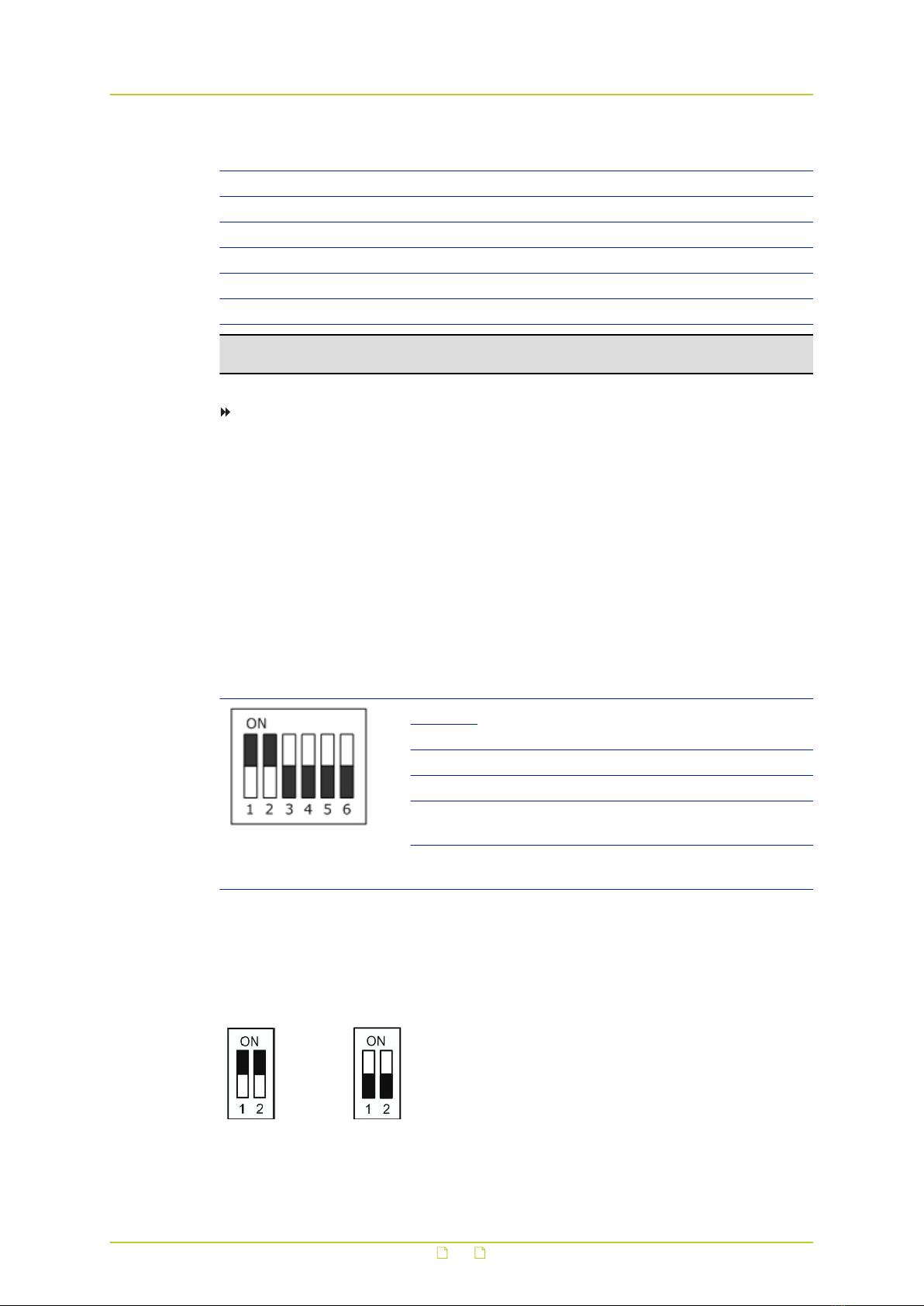
4.2 Communication switch configuration
The communication switch of the HSD626EXP is specified in the table below. The default
settings are depicted in the figure. You are advised to verify the accuracy of the
communication switch configuration but do not change the default settings, or some functions
may not work properly.
Communication switch Switch Description
1 RS-485
2
3 Termination
4 Line lock
5 System initialisation. Switch 5 is mainly used to
restore the factory defaults of the camera.
6 Camera upgrade. Users must reset switch 6 after
firmware upgrades are carried out.
RS-485 is the interface that enables communication between the HSD626EXP and its control
device. This means that the RS-485 setup of the camera and that of the control device must
be the same. The RS-485 default setting is half-duplex, as shown in the figure below. Do not
change the default setting without consulting a qualified specialist or supplier.
Half duplex Full duplex
RJ-485 settings
Dome camera setup
14

4.3 Establish a network connection
The webpages of the HSD626EXP provide a convenient way of accessing its settings. You can
log on to the internal web server of the HSD626EXP from a PC which is on the same subnet as
the unit. Follow the steps below to open communication with the HSD626EXP and configure its
network settings.
Step 1: Set the network adapter of the PC to the factory-set subnet of the
HSD626EXP and then connect the two devices to the network.
Step 2: Access the unit from a web browser or other tool installed on the PC.
Step 3: Set the IP address and subnet mask of the HSD626EXP to the subnet that it
is going to be used in and reboot the unit.
To address the unit from the same PC again, configure the network adapter of the PC once
more to assign the PC to the same subnet as the unit.
Step 1: Set the PC to the factory-set subnet of the unit
To configure the network adapter on the PC
1 In Control Panel, open Network and Sharing Center.
2 Select the connection to be configured, and then click Properties.
3 On the items list, select Internet Protocol Version 4 (TCP/IPv4).
4 Click Properties.
5 In the Internet Protocol Version 4 (TCP/IPv4) Properties dialog box, click Use the
following IP address.
6 Enter an IP address which assigns your PC to the same subnet as the HSD626EXP - that
is, within the 10.x.x.x range. Use 255.0.0.0 as a subnet mask.
Important: To prevent conflicts, be sure to choose a unique IP address. No two
devices on a network can have the same IP address.
7 To apply the new settings, click OK.
Setting the IP settings of the PC to the factory-set IP settings of the unit
Dome camera setup
15

At this point, connect your PC to the HSD626EXP. You can connect them directly using a
crossover cable, or connect both to a switch.
Step 2: Access the unit
Using a standard web browser you can now log on to the web server of the HSD626EXP.
Step 3: Change the network settings of the unit
The Network page enables you to make the network addressing of the unit compatible with
the network it will be added to. You can set a fixed IP address or have the IP address assigned
by a DHCP server. In the latter case, open the Advanced Settings and enable DHCP. Do not
forget to save and reboot the unit after changing the settings.
4.4 System compatibility
To ensure system compatibility, download the latest firmware at http://www.siqura.com/.
4.5 RJ-45 to SFP changeover
To install the SFP interface safely into the HSD626EXP camera, follow these instructions.
Important: For safety information, see the instructions in the Safety chapter of this manual.
Failure to comply with any precaution, warning, or instruction noted there is in violation of
the standards of design, manufacture, and intended use of the module. Siqura assumes no
liability for the customer’s failure to comply with any of these safety requirements.
To install the XSNet SFP interface on the HSD626EXP camera
1 Remove the black mounting screw highlighted below.
2 Align the connector and install the SFP end cap.
3 Replace the mounting screws.
Dome camera setup
16
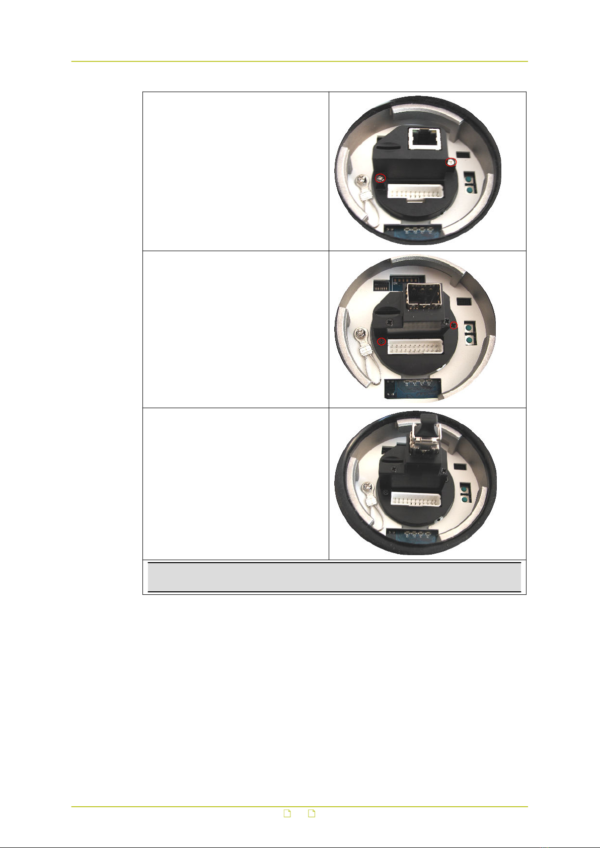
● Unscrew the captive mounting screws
and remove the RJ-45 end cap cover.
● Align the connector, insert the SFP end
cap, and screw in the captive mounting
screws.
● Insert the SFP connector.
Important: Be sure to follow the safety instructions with regards to optical safety and
fiber handling precautions.
4.6 Dome cable definition and requirements
For operation, the HSD626EXP cameras require either an Ethernet cable or an appropriate
fiber optic cable to carry the signals to a remote viewing site and a cable to power the dome.
Dome camera setup
17

4.6.1 Cable requirements
For operation, the camera requires a video and cable harness, as described below.
● A cable to provide a 24 Vac power supply to the dome.
● A Cat 5 Ethernet cable.
● Optional audio cables.
● Optional coaxial cable to monitor analogue video.
Important: Make sure that the power supply corresponds with the power requirement of
the dome, or damage will occur. If any mistake happens, contact a qualified technician.
4.6.2 Verifying Ethernet connectivity
Refer to the following figure to determine whether you have established an Ethernet
connection.
Ethernet socket LEDs green/yellow
Green on/off : 100/10 Mbit
Yellow on/blink : link OK, active
Yellow off/flash : link down, TX attempt
4.6.3 22-pin cable harness
The 22-pin cable harness of the HSD626EXP
4.6.4 22-pin connector definition
With the 22-pin connector, installers can simply connect the power and video cables to the
dome at the same time. The alarm pins are serviceable for connecting alarm input and output
devices, such as alarm sensors, sirens, or flashing lights with the surveillance system. For the
definition of each pin, see the table below.
22-pin connector
The definitions of each pin are listed in the following table.
Dome camera setup
18

Pin Definition Cable Color Rating
1 AC 24-1/DC (+) 20/18 AWG Red
2 Alarm, normally closed White Photo Relay output 300 V
3 AC 24-2/DC (-) 20/18 AWG Black
4 Alarm, normally open White/black Photo Relay output 300 V
5 FG 20/18 AWG Yellow
6 Alarm COM
24 AWG
Green/black Photo Relay output 300 V
7 Audio in Yellow/black
8 Audio out Orange/black
9 Audio GND Green/black
10 Audio GND Brown/black
11 ISOG Blue/white
12 Alarm 1 Red/white
Input 5 V 10 KΩ pull up
Photo Relay output 300 V
13 Alarm 3 Purple
14 Alarm 2 Gray
15 Alarm 4 Blue
16 Alarm 5 White/black
17 Alarm 6 Orange/black
18 Alarm 7 Purple/white
19 Alarm 8 Gray/black
20 Alarm GND Brown/white Input 5V 10 KΩ pull up
21 Video GND
20 AWG
Black/gray
22 Video Red/gray
Dome camera setup
19

5 System integration
The HSD626EXP dome camera can be integrated into other suppliers' surveillance systems in
two ways:
● Via the Open Streaming Architecture (OSA) application programming interface (API). For
more information see the Siqura Programming Interface document or contact your supplier
for details.
● Via serial tunneling using the Pelco D protocol. For Pelco D, set both the UART gap timeout
and the UART max latency to 7. This ensures efficient and accurate transmission of the
commands. Other serial servers will likely use different terms for these settings. The
HSD626EXP's default baud rate is set to 9600. Ensure that your control keyboard uses a
compatible baud rate. The factory set ID number is 1 and you must not change this
setting. For applications that require a unique RS-485 ID, please contact Siqura for
assistance.
20
Table of contents
Other Siqura Security Camera manuals

Siqura
Siqura FD820M1IR User manual

Siqura
Siqura CD820 Series User manual

Siqura
Siqura HD10A User manual

Siqura
Siqura HSD 62 Series User manual

Siqura
Siqura BL2002M1-EI User manual

Siqura
Siqura MSD620 User manual

Siqura
Siqura BL2002F4-EI User manual

Siqura
Siqura 1002 Series User manual

Siqura
Siqura IFD820V1IR User manual

Siqura
Siqura FD2x Series User manual

Siqura
Siqura MD20 User manual

Siqura
Siqura PD910 User manual

Siqura
Siqura HSD622 User manual

Siqura
Siqura FD2005M1-EI User manual

Siqura
Siqura BC2xSeries User manual

Siqura
Siqura sa fixed series User manual

Siqura
Siqura FD12 Owner's manual

Siqura
Siqura BL2005M1-EI User manual

Siqura
Siqura CD820F1 User manual

Siqura
Siqura FD1103 User manual


