Siqura FD12 Owner's manual

Installation
and Operation
Siqura FD12
Vandal Proof Fixed Dome Camera


i
Contents
CONTENTS
1. PREFACE .........................................................................................................1
1.1. CHANGE LOG ...................................................................................................2
2. CAUTIONS.......................................................................................................3
3. OVERVIEW ......................................................................................................5
3.1. PRODUCT FEATURES ...........................................................................................5
4. PACKAGE CONTENTS ........................................................................................7
5. CAMERA CONFIGURATION .................................................................................9
5.1. PARTS DEFINITION.............................................................................................9
5.2. SIQURA FD12 SWITCHES,CONNECTORS,AND BUTTONS..................................................9
5.3. 10-POLE DIP SWITCH....................................................................................... 10
5.3.1. DIP switch settings ................................................................................ 11
5.4. TERMINAL BOARD ............................................................................................ 12
6. INSTALLATION............................................................................................... 13
6.1. HARD CEILING INSTALLATION............................................................................... 13
6.2. 4S MOUNT ELECTRICAL BOX................................................................................ 17
APPENDIX A: TECHNICAL SPECIFICATION................................................................... 19
APPENDIX B: TROUBLESHOOTING ............................................................................. 21

ii

1
Preface
1. PREFACE
The information given in this manual was current when published. The company reserves the
right to revise and improve its products. All specifications are subject to change without
notice. The most recent version of this manual is on the Optelecom-NKF website, at
www.optelecom-nkf.com.
Notice
To work with the Siqura FD12 camera, an installer or technician must have the
following minimum qualifications:
•A basic knowledge of CCTV systems and their components.
•A basic knowledge of electrical wiring, and low-voltage electrical connections.
•Have read this manual completely.
Copyright
Under copyright laws, the contents of this installation manual may not be copied,
photocopied, translated, reproduced or reduced to any electronic medium or machine-
readable format, in whole or in part, without prior written permission of the company.
Important information
Before proceeding, please read and observe all instructions and warnings in this manual.
Retain this manual with the original bill of sale for future reference and, if necessary,
warranty service. When unpacking your unit, check for missing or damaged items. If any
item is missing, or if damage is evident, DO NOT INSTALL OR OPERATE THIS PRODUCT.
Contact Optelecom-NKF for assistance.

2
Preface
Regulations
This device complies with Part 15 of the FCC Rules.
Operation is subject to the following two conditions:
(1) this device may not cause harmful interference, and
(2) this device must accept any interference received,
including interference that may cause undesired
operation.
This symbol on the product or on its packaging
indicates that this product shall not be treated as
household waste in accordance with Directive
2002/96/EC. Instead it shall be handed over to the
applicable collection point for the recycling of electrical
and electronic equipment. By proper waste handling of
this product you ensure that it has no negative
consequences for the environment and human health,
which could otherwise be caused if this product is
thrown into the garbage bin. The recycling of materials
will help to conserve natural resources.
For more detailed information about recycling of this
product, please contact your local city office, your
household waste disposal service or the seller of the
product.
Compliance is evidenced by written declaration from our
suppliers, assuring that any potential trace
contamination levels of restricted substances are below
the maximum level set by EU Directive 2002/95/EC, or
are exempted due to their application.
1.1. Change Log
Manual version 1.1 contains corrected power supply information.
Manual version 1.2 contains corrected day/night information.
Manual version 1.3 contains corrected pin connector assignment information.

3
Cautions
2. CAUTIONS
Only qualified service personnel or system installers should install and connect
this product.
Handle the camera carefully.
Avoid striking, shaking, etc. as the camera can be damaged by improper handing or
storage.
Do not disassemble the camera.
To prevent electric shock, do not remove screws or covers. There are no user serviceable
parts inside. If necessary, ask a qualified technician for servicing.
Do not operate the camera beyond the specified temperature, humidity and
power source ratings.
Verify the power source is appropriate before you plug in and operate the unit.
If the camera is installed outdoors, make sure it is sheltered from direct sunlight.
Do not use strong or abrasive detergents when cleaning the camera.
Use a dry cloth to clean the camera when it is dirty. If the dirt is hard to remove, use a
mild detergent and wipe gently. To clean the lens, use lens tissue or a cotton tipped
applicator and ethanol. DO NOT clean the lens with strong detergents.
Never face the camera towards the sun.
Do not aim the camera at bright objects. Whether the camera is in use or not, never aim
it at the sun or other extremely bright objects. Otherwise, the camera may be damaged.


5
Overview
3. OVERVIEW
The Siqura FD12 is a 1/3” CCD color fixed dome camera designed for both indoor and
outdoor video surveillance systems with ultraviolet ray prevention and vandal-proof housing,
and compliant with the international IP66 water resistant standard. This dome camera is
equipped with Back Light Compensation, Auto Exposure and Automatic Gain Control
functions that work together to achieve a consistent video output level, while a signal-to-
noise ratio of more than 50 dB and 520 TVL High Resolution ensure image clarity.
Additionally, the camera’s built-in Blue Glass Optical Filter allows the user to improve and
enhance pictures’ hue. With integrated features and functions, the Siqura FD12 promises
tight security and provides optimum pictures.
3.1. Product Features
Dome Body
•Dust- and waterproof (IP 66 Standard)
•Special nail design guards against theft
•Vandal-proof structure with metallic base
•3-D hinge (Pan, Tilt and Rotation)
•Internal Heater and Fan
•Mounting: Hard Ceiling, 4S Electrical Box Support
•AC 24V Dual Power Support
Camera
•Horizontal resolution > 520 TV lines (540 TVL Max.)
•Day/Night function
•High Sensitivity, Low Smear and High S/N Ratio
•Anti-color-rolling
•CCD Blemish Compensation
•Backlight Compensation (BLC)
•Automatic Tracing White Balance
•Automatic Iris Control
•Automatic Gain Control (AGC)
•Mirror Function
•Electronic Shutter
•Flickerless Mode
•Suppress Function
•Built-in Anti-aliasing Optical Low Pass Filter
Refer to Appendix A: Technical Specification for more detailed information.


7
Package Content
4. PACKAGE CONTENTS
Before proceeding, please check that the box contains the items listed here. If any item is
missing or defective, DO NOT install or operate the product. Contact Optelecom-NKF for
assistance.
Self tapping screws
Safety Screw
Dome Camera
(with Power and Video cables
/ L: 30 cm )
Security TORX
Plastic Screw Anchors
Cable Gland

9
Camera Configuration
5. CAMERA CONFIGURATION
Before installing the camera, read this chapter completely and configure the camera’s
settings.
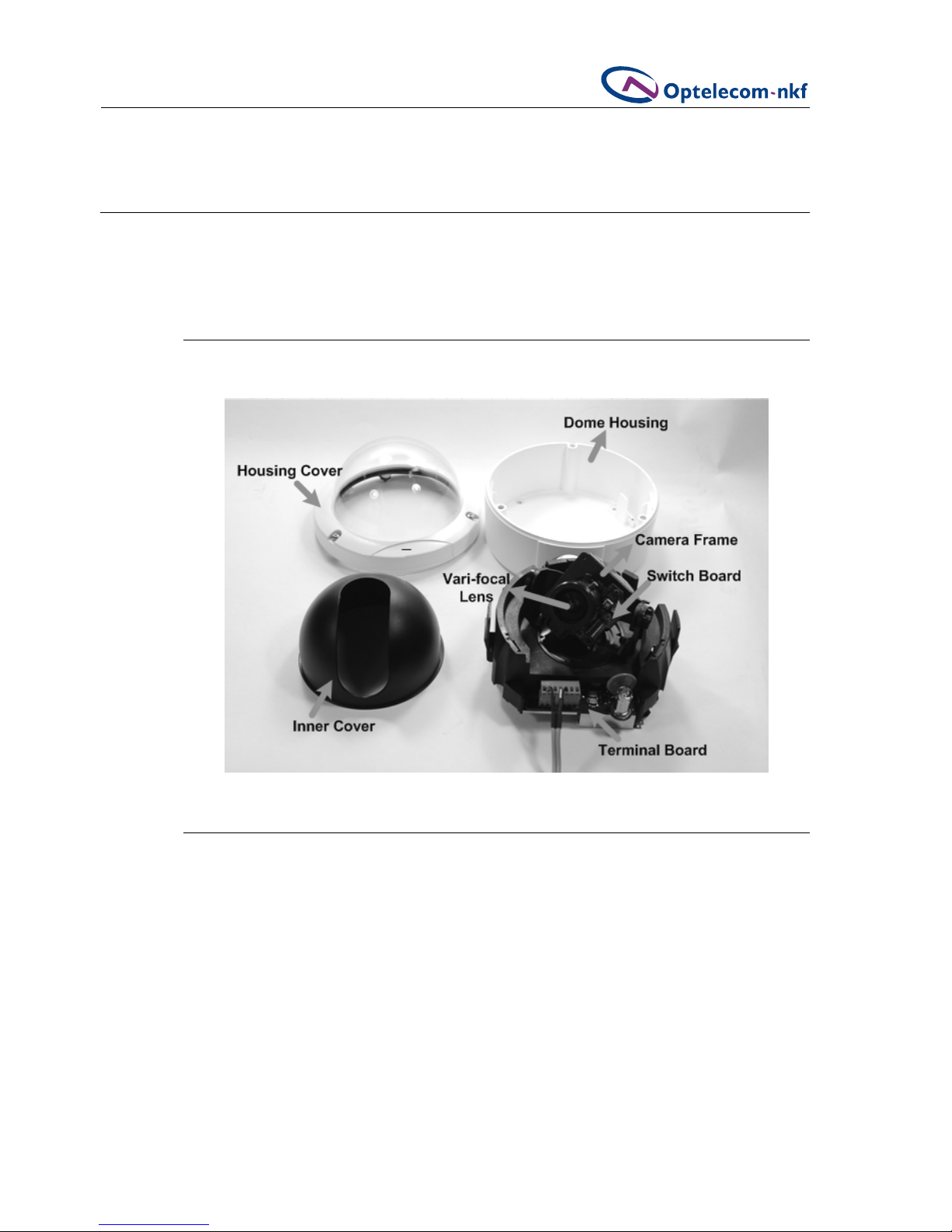
5.1. Parts Definition
Before installing, configure the camera settings according to the instructions below.
5.2. Siqura FD12 Switches, Connectors, and Buttons
Users can enable or disable the functions on the switch board based on the camera’s
installation environment to achieve better video quality and performance. This section
describes the switch definitions and functions of the 10-pole dip switch.

10
Camera Configuration
5.3. 10-Pole Dip Switch
5.1 Switch Board (10-pole Dip Switch)
DC Auto Iris Switch:
Use this switch to adjust camera video image brightness. Turn the switch clockwise to
brighten the video image, and counter-clockwise to dim the image.
Switch Definition Remarks
1 AI_AE Auto Iris, Auto Exposure
2 AGC Auto Gain Control
3 BLC Back Light Compensation
4 FLS Flickerless Mode
5 MIRROR Mirror Function
6 GAMMA Gamma Correction
7 Reserved
8 D/N Day/Night Function
9,10 Reserved
Table 5.1 10-Pole Switch

11
Camera Configuration
5.3.1. DIP switch settings
Switch Function Description
AE OFF enables Auto Iris (AI) mode.
ON enables Auto Exposure (AE)
mode.
Default=OFF.
In AE mode, the camera’s shutter and
AGC control circuits work together
automatically to compensate the light
exposure of the CCD sensor in order to
get a consistent video output level.
When AE is switched on, the Iris is
fixed.
Note: When using an Auto Iris lens,
this switch should be set to OFF so
that Auto Iris can take effect.
AGC OFF disables AGC mode
ON activates AGC mode
Default=OFF.
AGC improves camera sensitivity and
provides clear image in low
illumination conditions.
BLC OFF disables BLC function
ON activates BLC function
Default=ON.
The BLC function solves the problem of
backlight scene by brightening the
foreground object.
FLS OFF disables flickerless mode
ON activates flickerless mode.
Default=OFF.
When the frequencies of the power
supply and the camera are different,
the problem of image flicker may
occur. Activation of the Flickerless
mode can help remove flicker.
MIR OFF disables Mirror function
ON activates Mirror function
Default=OFF.
The Mirror function reverses the image
horizontally.
GAMMA OFF sets Gamma encoding to 0.45.
ON sets Gamma encoding to 1.0.
Default=OFF.
Controls the brightness of the image
based on the expected viewing device.
When the switch is OFF, encoding is
standard NTSC; when ON, no Gamma
correction is applied to the outgoing
image.
INT/EXT INT enables auto IR function
EXT sets IR function to be
controlled by alarm input
Default=INT.
When the switch is set to INT (Internal
Auto), control of IR is determined by
CCD; while the switch is set to EXT,
control of IR is dependent on external
alarm input.
LL Reserved

12
Camera Configuration
5.4. Terminal Board
The figure below shows the dome camera’s terminal board. Pin definitions for the power and
video terminal block are listed below.
Figure 5.2 Terminal Board
Pin Definition
1 Power 12V DC +
2 Power 12V DC -
3 Earth (GND)
4 Video Out
5 Video GND
6 Reserved
7 Reserved
Table 5.2 12V DC terminal board pins
Pin Definition
1 Power 24V AC +
2 Power 24V AC -
3 Earth (GND)
4 Video Out
5 Video GND
6 Reserved
7 Reserved
Table 5.3 24V AC terminal board pins
please note The optional Siqura PA01 24V AC is delivered without connectors. The
installer must manually wire it to the camera.

13
Installation
6. INSTALLATION
Read the instructions provided in this chapter thoroughly before installing the Siqura FD12
dome camera. Refer to the diagrams below for dome dimensions.
Figure 6.1 Top View Figure 6.2 Side View
6.1. Hard Ceiling Installation
The Siqura FD12 can be installed directly on a wall or ceiling. Please note that the wall or
ceiling must have enough strength to support the dome camera.
To install your dome camera in a hard ceiling
1. Use the hexagon tool to unscrew and remove the
housing cover.
2. Gently press both sides of the inner cover and remove
it from the dome unit.

14
Installation
3. Press the sides of the snap-on module, as indicated in
the figure, and detach it from the dome housing.
4. Attach the dome housing to the appropriate mounting
location on the wall, and mark the positions of the four
screw holes with a pen or a pencil.
5. In the marked locations, drill a hole slightly smaller
than the supplied screw anchors.
6. Insert the anchors into these holes.
7. Fasten the dome housing with the four supplied
screws.
8. Thread the power and video cables through either the
side conduit entry or back conduit entry. Users may
use a coin to screw the conduit entry block off.

15
Installation
9. Attach the snap-on module into the dome housing.
please note The terminal block should face the side
conduit entry, as shown in the figure.
10. Connect the power and video outputs
Pan Adjustment
11. After the dome body is mounted and the cables are
connected, the image should be displayed on the
monitor. Adjust the camera to a desired angle, as
shown in the three figures to the right.
Rotation Adjustment
Tilt Adjustment

16
Installation
12. Rotate the lens to adjust the camera's zoom level and
focal length.
Adjust the zoom ring screw to set the desired zoom
and modify the focus ring screw to set the desired
focal length.
13. Determine the camera settings. Refer to Section 5.2
Camera Configuration: Switch Board for details.
14. Replace the inner cover back on the camera unit.
15. Screw the housing cover tightly to the dome body.
Table of contents
Other Siqura Security Camera manuals
-SFP User manual")
Siqura
Siqura FD820M1(IR)-SFP User manual

Siqura
Siqura BC820 User manual

Siqura
Siqura FD2005M1-EI User manual

Siqura
Siqura HSD820 Series User manual

Siqura
Siqura HSD622 User manual

Siqura
Siqura XCU Series User manual

Siqura
Siqura HSD820H3EXP User manual

Siqura
Siqura SA-BL37 User manual

Siqura
Siqura sa fixed series User manual

Siqura
Siqura XCU Fusion User manual

Siqura
Siqura BL2005M1-EI User manual

Siqura
Siqura MSD620 User manual

Siqura
Siqura MSD622 User manual

Siqura
Siqura FD2x Series User manual

Siqura
Siqura PD900 Series User manual

Siqura
Siqura CD820F1 User manual

Siqura
Siqura PD910 User manual

Siqura
Siqura MD20 User manual

Siqura
Siqura HSD820V2H3-E User manual

Siqura
Siqura HSD626EXP User manual


T user manual")