Sirman PLL 300 User manual
1
GRAVITA’
PLL 300-330-350 AUTOMATICA
EC Professional Slicer
USE AND MAINTENANCE MANUAL

2
FOREWORD
•This manual is meant to provide Customers with information on the machine and its
specifications, and provides all the necessary operating and maintenance instructions in
order to ensure machine performance and longevity.
•This manual must be kept until the machine is disposed of. This manual should be accessible
to all maintenance and operating personnel.
CONTENTS
CHAP. 1 - RECEIVING THE MACHINE page 4
1.1 -PACKAGING
1.2 -PACKAGING UPON DELIVERY
CHAP. 2 - INSTALLATION page 6
2.1 UNPACKING
2.2 POSITIONING
2.3 -ELECTRICAL CONNECTION
2.3.1 - Slicer with single-phase motor
2.3.2 - Slicer with 400 V. three-phase motor
2.3.3 - Slicer with 230 V. three-phase motor
2.3.4 - Blade rotation direction
2.4 - WIRING DIAGRAM
2.5 CONTROL PANEL
2.6 -PRELIMINARY CHECK
CHAP. 3 - INFORMATION ON THE MACHINE page 11
3.1 -GENERAL SAFETY PRECAUTIONS
CHAP. 4 - GETTING FAMILIAR WITH THE SLICER page 13
4.1 CONSTRUCTION FEATURES
4.2 -SAFETY DEVICES INSTALLED ON THE MACHINE
4.2.1 -Mechanical safety
4.2.2 -Electrical safety
4.3 - DESCRIPTION OF THE MACHINE
4.4 - OVERALL DIMENSIONS, WEIGHT, FEATURES….
CHAP. 5 - USING THE MACHINE page 18
5.1 - OPERATIONAL CHECK
5.1.1 - Using the controls
5.2 - LOADING AND CUTTING THE PRODUCT
5.3 -SHARPENING THE BLADE

3
page 22
CHAP. 6 - ROUTINE CLEANING
6.1 - FOREWORD
6.2 - CLEANING THE MACHINE
6.2.1 - Cleaning the goods holder plate
6.2.2 - Cleaning the blade, the bladeguard and the ring
6.2.3 - Cleaning the greaseguard
6.2.4 - Cleaning the sharpener
6.3 -SLIDE GUIDES LUBRICATION
CHAP. 7 - MAINTENANCE page 26
7.1 FOREWORD
7.2 BELT
7.3 FEET
7.4 FEEDING CABLE
7.5 BLADE
7.6 GRINDERS
7.7 -SLIDE GUIDES LUBRICATION
7.8 - PUSH-BUTTON PANEL LABEL
7.9 ERROR CODES
CHAP. 8 - DISMANTLING page 28
8.1 -PUTTING THE MACHINE OUT OF SERVICE
8.2 SCRAPPING
8.3 - WEEE Waste of Electric and Electronic Equipment
4
CHAP. 1 - RECEIVING THE MACHINE
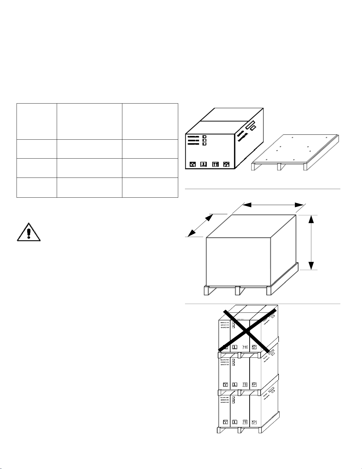
1.1 - PACKAGING
The slicer is shipped (Fig. n°1) on wooden pallets and packed in a cardboard box and covered in
protective nylon. Packaging materials must be disposed of separately and in conformity with waste
treatment legislation of the country of destination.
Dimensions
AxBxC Gross
weight
(Kg)
PLL 300 780x640x700 46
PLL 330 780x640x700 47
PLL 350 780x640x700 48
Do not stack more than one machine on top of
another (Fig. n°3).
WARNING! B
A
C
Fig. n°1
Fig. n°2
Fig. n°3
5
If packaging shows signs of damage caused
during transport, the carrier must be informed
immediately; moreo-ver a detailed report on the
extent of the damage caused to the machine
must be notified to the carrier within three days
from the delivery date on the shipping
documents. If there are no
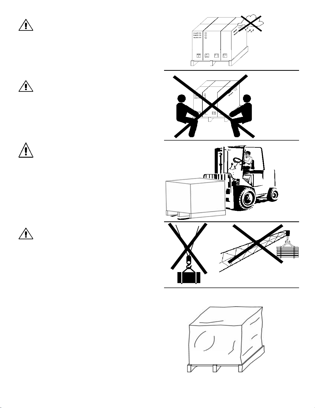
1.2 - CHECKING PACKAGING UPON DELIVERY
Heavyweight package. Do not manually lift without
the help of at least three people
(Fig. n°5).
To handle andmove the package use suitable
manual or electric material handling equipment
fitted withsuitable lifting accessories (Fig. n°6).
Do not expose the package to humidity or rain
(Fig. n°4).
As the centre of gravity of the package is off-centre
do not to use lifting slings (Fig. 7)) to ove the
package (Fig. n°7).
Fig. n°4
Fig. n°6
Fig. n°5
Fig. n°8
Fig. n°7
This manual suits for next models
2
Table of contents
Other Sirman Kitchen Appliance manuals

Sirman
Sirman TC RIO 22 User manual

Sirman
Sirman PPJ 10 SC Specification sheet

Sirman
Sirman Topaz 195 Operating instructions

Sirman
Sirman MNT 300 Operating instructions

Sirman
Sirman Mirra Series Operating instructions

Sirman
Sirman Easyvac 25 User manual

Sirman
Sirman PPJ20 Specification sheet

Sirman
Sirman PALLADIO EVO 330 Operating instructions

Sirman
Sirman Stromboli Assembly instructions


