SIRS-E Pilotino-WiFi User manual

E518483

INDEX
1. Introduction
2. Safety Information
3. Electrical Specifications
4. Onboard Features (Nomenclature)
5. Mechanical Details
6. Installation
7. DMX Addressing
8. RDM and Available PID’s
8.1 RDM PID’s Description
8.2 Output Curve
8.3 Output Frequency
8.4 Bit Mode Selection
8.5 DMX Failure Settings
8.6 Response Time
8.7 Default Settings
8.8 Onboard Settings
9. Mode LED Indicator
10 . Hardware and Accessories
UL Certification
2
Pg. 3
Pg. 4
Pg. 4
Pg. 5
Pg. 6
Pg. 7
Pg. 8
Pg. 9
Pg. 10
Pg. 12
Pg. 16
Pg. 18
Pg. 19
Pg. 19
Pg. 20
Pg. 22
Pg. 22
Pg. 23
Pg. 25
R
3307 West Street Rosenberg, TX 77471 USA - (281) 324-0908
Copyright © 2006-2021 SIRS Electronics Inc. All Rights Reserved P ™ PCB Instruction Manual
ILOTINO
Updated 12/2021. Rev 2.8

1. Introduction
Key Features:
Wireless Capability
UL Regconized
DMX Ready
RDM Configurable
RDM Data Feedback
Selectable Output Frequency
The P ™ PCB is the newest addition to the LED CV DMX decoder family for SIRS-E. Control any
ILOTINO
kind of CV LED Strip, COB, and other constant voltage LED products. This version of the P ™ comes in
ILOTINO
a bare PCB format. This product is intended to be embedded into custom fixtures and lighting control
systems in which component size is critical. Equipped with 6 mounting holes, the P ™ PCB is ready
ILOTINO
to be installed with M2.5 X 5mm stand-offs into any sort of enclosure.
R
P ™ PC
ILOTINO B
UL Class 2 Output Certified
Input CertifiedUL Registered
Onboard IO Socket (For Connectivity)
Small Footprint
Wire to Board Quick Connectors
Standoff Mounting
5 Year Limited Warranty
Made in Italy
3
3307 West Street Rosenberg, TX 77471 USA - (281) 324-0908
Copyright © 2006-2021 SIRS Electronics Inc. All Rights Reserved
E518483
Package Contents
P ™ PCB - : Pilotino-PCB
ILOTINO SKU
P ™ PCB Instruction Manual
ILOTINO
Updated 12/2021. Rev 2.8
Check our page Check our YouTube Video!

2. Safety Information
Safety Information
3 Electrical S. pecifications
The exposed PCB design of this product results in a major reduction in its foot print. With a slim and narrow design, this
configuration is intended to be used in applications that would benefit from this feature. Some examples of applications
include: fixture integration, custom control enclosures, and others. The exposed design comes with few precautions to
take notice of.
The P ™ PCB is a non-waterproof device with an IP 20 rating. Keep the unit dry at all times and away from liquids
ILOTINO
and humid environments. Make all connections to the LEDs and driver prior to powering on the circuit. All lead voltage
connections to the drivers must be performed by a licensed electrician. Do not touch any of the surfaces of the device
once the unit is powered on. Ensure that all connections are secure and eliminate all possibilities of shorting the unit.
Use the proper wire gauge for the wire to board connections and wiring blocks. We recommend using 12awg stranded
wire for the power input, and 18awg for the output connections that connect to the LEDs. Do not mount the unit where
vibrations or shock are present. Be sure that the thermal pad is attached to the back of the unit at all times.
WARNING - Risk of Fire or Electrical shock, do not interconnect output terminations
Ambient Operating Temperature: -10 °C - 45 °C
Relative Humidity: 5% - 80% non-condensing
IP Rating: IP 20 Non-waterproof (Keep dry)
Ventilation: Do not install in airtight spaces
Input Control protocol: DMX512-A
RDM: Yes
Control Options
DMX Resolution: 8/16 bit Selectable
Wi-Fi: ArtNet with P WiFi™ PCB
ILOTINO
CRMX: Lumen Radio with P CRMX™ PCB
ILOTINO
Ambient Parameters
Max Current / Channel: 2.5A
Working Voltage: 12-24V DC
Output Channels: 1-5 Selectable
Output Frequency: 1-5.2KHz PWM
UL Class 2 Output
Max Power / Channel: 30W @12V / 60W @24V
Max Power Out: 150W @12V / 300W @24V
Max Current: A12.5
Working Voltage: 12-24V DC
Max Power In: 150W @12V / 300W @24V
Input Voltage (UL Non-class 2)
4
3307 West Street Rosenberg, TX 77471 USA - (281) 324-0908
Copyright © 2006-2021 SIRS Electronics Inc. All Rights Reserved P ™ PCB Instruction Manual
ILOTINO
Updated 12/2021. Rev 2.8

4. Onboard Features
1. I/O Connection Socket + DMX in (For expansion Modules)
2. DMX IN/OUT Wire to board connector (As shown top to bottom: GND, D-, D+)
3. Dip Switches for DMX Addressing and other functions
4. Mounting holes for Standoffs M2.5 (metric)
5. Output wire to board connector Channel 1
6. Output wire to board connector Channel 2
7. Output wire to board connector Channel 3
8. Output wire to board connector Channel 4
9. Output wire to board connector Channel 5
10. Output wire to board dual connector COMM V+
11. Power Input wiring block connector
12. Mode Indicator LED
13. Thermal Pad (Do Not Remove)
5 6 7 8 9
10
34 4 4
24 44
1
11
12
13
5
3307 West Street Rosenberg, TX 77471 USA - (281) 324-0908
Copyright © 2006-2021 SIRS Electronics Inc. All Rights Reserved P ™ PCB Instruction Manual
ILOTINO
Updated 12/2021. Rev 2.8

5. Mechanical Details
P ™ PCB
ILOTINO Top View
P ™ PCB Side View
ILOTINO
45.09mm
22.23mm
48.26mm45.72mm
15.88mm
9.02mm
43.75mm
170.2 mm5
10.8mm 23.22mm
6
3307 West Street Rosenberg, TX 77471 USA - (281) 324-0908
Copyright © 2006-2021 SIRS Electronics Inc. All Rights Reserved P ™ PCB Instruction Manual
ILOTINO
Updated 12/2021. Rev 2.8

6 Installation.
Thermal Pad
The thermal pad that dissipates heat from the components of the device must always be used. This thermal pad is
included with each P ™ PCB
ILOTINO and comes installed from factory. Proper ventilation should be present within the
enclosure in which the unit is installed.
Standoffs
Six 2.5M x 5mm standoffs should be used to properly mount the unit onto a smooth and level surface. It is
recommended that the included factory 2.5M standoffs be used. To fasten the P ™ PCB onto a surface, first
ILOTINO
tighten the four central screws in a crisscross pattern. Once the central screws are torque down to ¼ turn past
hand tight, do the same for the remaining 2 screws. Always tighten the screw opposite to the last screw that was
torque down. Do not over tighten the screws as doing so will result in damage to the device.
Clearance
Due to the exposed contact points on the P ™ PCB, the risk of shorting the unit should be considered. A
ILOTINO
minimum of 10mm of clearance space is recommended. Never install the P ™ PCB within an enclosed space in
ILOTINO
which the P ™ PCB does not have sufficient space away from other components.
ILOTINO
Connections
The P ™ PCB comes equipped with wire to board connectors, and a socket connector for the connectivity
ILOTINO
expansion modules. All wire connections should fit securely into the connectors; therefore, we recommend to used solid
wire when installing LED strips and power cable wires. Be sure to insert each wire into the connectors deep enough so
that no bare wire is exposed. A good rule of thumb is to strip the wires so that only about 3mm of insulation is removed.
Always use both output terminals for the COMM V+ connection (See section 4, “Onboard Features” for more details).
The P ™ PCB can be connected in a daisy chain format for the distribution of DMX signal. Never daisy chain more
ILOTINO
than 30 P ™ PCB in a single line. For larger projects, make use of DMX splitters to distribute the DMX data.
ILOTINO
Settings
All of the advanced settings in the P ™ are meant to be accessed through RDM connectivity only. Any setting
ILOTINO
beyond the DMX addressing can only be edited through the use of an RDM controller or software. The P ™ is
ILOTINO
equipped with the latest version of RDM and is compatible with any controller, board, or software capable of RDM.
7
3307 West Street Rosenberg, TX 77471 USA - (281) 324-0908
Copyright © 2006-2021 SIRS Electronics Inc. All Rights Reserved P ™ PCB Instruction Manual
ILOTINO
Updated 12/2021. Rev 2.8

7. DMX Addressing
DMX Addressing
The P ™ PCB can be addressed by setting the onboard DIP switches in the following way:
ILOTINO
(Be sure to perform all connections prior to turning on the power supply.)
1. Connect the input power from the power supply
2. Connect the LEDs to the output wire to board connectors
3. Connect the DMX input to the connectors or achieve a wireless connection with the CRMX module
4. Switch ON the power supply
5. The green indicator LED will turn on steady
6. Set the desired address by following the binary value expressed by the DIP switch positions
7. DIP 1-9 Set DMX address: “Base 1” numbering is adopted with DMX channel 1= Code 1
DMX Channel 512=Unavailable
8. The green indicator LED will now flash steadily if the DMX signal is present
* To select DMX address with RDM compatible software , switch ON the DIP switch 10 and use the “DMX Start
Address” menu.
8
3307 West Street Rosenberg, TX 77471 USA - (281) 324-0908
Copyright © 2006-2021 SIRS Electronics Inc. All Rights Reserved P ™ PCB Instruction Manual
ILOTINO
Updated 12/2021. Rev 2.8

8. RDM and Available PIDs
What is RDM?
RDM, or Remote Device Management, is a standardized bi-directional communication protocol used for managing,
monitoring, and configuring lighting fixtures and other equipment that come equipped with RDM capability. This
protocol is an enhancement of the USITT DMX512 protocol that is commonly used for configuring a wide array of
lighting fixtures and other equipment.
Pilotino™ and RMD
The Pilotino™ comes equipped with full RDM capability and is compatible with any kind of RDM software, board, or
controller. All of the advanced settings that the Pilotino™ is capable of can only be edited through an RDM device. The
only setting that does not require an RDM device is the DMX addressing. This can be done through the onboard DIP
switches (More information on addressing the Pilotino™ is available on page 9).
What are PIDs?
A PID within the RDM context is a certain parameter or setting that is available through the RDM protocol for
configuring a fixture or a piece of equipment. Each PID can “Get” or “Set” information for configuring an RDM capable
device.
Available PIDs for Pilotino™
DMX START ADDRESS - SET
FACTORY DEFAULTS - SET
CURVE - SET
CURVE DESCRIPTION - GET
DMX PERSONALITY - SET
DMX PERSONALITY DESCRIPTION - GET
OUTPUT RESPONSE TIME - SET
OUTPUT RESPONSE TIME DESCRIPTION - GET
MODULATION FREQUENCY - SET
MODULATION FREQUENCY DESCRIPTION - GET
DMX FAIL MODE - SET
SENSOR VALUE SUPPLY VOLTAGE - GET
SENSOR VALUE INTERNAL TEMPERATURE - GET
SENSOR VALUE SUPPLY CURRENT - GET
SOFTWARE VERSION LABEL - GET
DEVICE HOURS - GET
LAMP HOURS - GET
SUPPORTED PARAMETERS - GET
DEVICE INFO - GET
DEVICE MODEL DESCRIPTION- GET
MANUFACTURER LABEL - GET
DEVICE LABEL - SET
IDENTIFY DEVICE - SET
9
3307 West Street Rosenberg, TX 77471 USA - (281) 324-0908
Copyright © 2006-2021 SIRS Electronics Inc. All Rights Reserved P ™ PCB Instruction Manual
ILOTINO
Updated 12/2021. Rev 2.8

8.1 RDM PID Descriptions
Used to configure the starting DMX address of the P ™ PCB.DMX START ADDRESS - SET: ILOTINO
Used to revert the P ™ PCB to factory default settings.FACTORY DEFAULTS - SET: ILOTINO
Used to set the Dimming Curve to achieve different dimming styles. There are 2 curve modes, CURVE - SET:
linear and quadratic.
Shows the currently selected Dimming Curve.CURVE DESCRIPTION - GET:
Used to set the desired output mode (1-5 channel 8 bit or 1-5 channel 16 bit). DMX PERSONALITY - SET:
The P ™ is capable of operating in 10 different Personality modes.
ILOTINO
Shows the currently selected DMX Personality.DMX PERSONALITY DESCRIPTION - GET:
Used to set the dimming response time related to the input signal.OUTPUT RESPONSE TIME - SET:
OUTPUT RESPONSE TIME DESCRIPTION - GET: Shows the currently set Output Response Time.
MODULATION FREQUENCY - SET: Used for configuring the PWM rate output frequency to the LEDs
(1-5.2KHz are available).
MODULATION FREQUENCY DESCRIPTION - GET: Shows the currently selected Modulation Frequency setting.
DMX FAIL MODE - SET: Used for configuring the action employed by the device in the event of a DMX signal failure
or loss. There are 3 fail modes to chose from: (1) Hold Last Value (2) Full , (3) Test= 60 DMX= 5% Output.
Shows a live feed of the input voltage value to the P ™.SENSOR VALUE SUPPLY VOLTAGE - GET: ILOTINO
Shows a live feed of the internal temperature of the P ™.SENSOR VALUE INTERNAL TEMPERATURE -GET: ILOTINO
Shows a live feed of the current draw of the P ™.SENSOR VALUE SUPPLY CURRENT - GET: ILOTINO
10
3307 West Street Rosenberg, TX 77471 USA - (281) 324-0908
Copyright © 2006-2021 SIRS Electronics Inc. All Rights Reserved P ™ PCB Instruction Manual
ILOTINO
Updated 12/2021. Rev 2.8

8.1 RDM PID Descriptions (cont.)
SOFTWARE VERSION LABEL - GET: Shows the current version of the P ™’s firmware.
ILOTINO
Shows the total hours of runtime that the device has completed since new.DEVICE HOURS - GET:
Shows the hours of runtime that the device has supplied to the LEDS. LAMP HOURS - GET:
Shows a list of all the available PIDs as implemented in the P ™.SUPPORTED PARAMETERS - GET: ILOTINO
Used to retrieve important device information.DEVICE INFO - GET:
Shows the ASCII text for the device model description.DEVICE MODEL DESCRIPTION- GET:
MANUFACTURER LABEL - GET: Shows the ASCII text for the manufacturer’s name.
Used to label the device by the user.DEVICE LABEL - SET:
Used for sending a strobing signal to the device’s outputs to identify its location.IDENTIFY DEVICE - SET:
11
3307 West Street Rosenberg, TX 77471 USA - (281) 324-0908
Copyright © 2006-2021 SIRS Electronics Inc. All Rights Reserved P ™ PCB Instruction Manual
ILOTINO
Updated 12/2021. Rev 2.8

Output Curve
The P ™ PCB has 2 output curve modes to select from: Quadratic and Linear.
ILOTINO
These modes can be accessed by setting the onboard DIP switches in the following way:
(Be sure to perform all connections prior to turning on the power supply.)
1. Connect the input power from the power supply
2. Connect the LEDs to the output wire to board connectors
3. Connect the DMX input to the connectors or achieve a wireless connection with the P CRMX™ PCBILOTINO
4. Switch ON the power supply
5. The green indicator LED will turn on steady
6. Switch DIP switch 10 to the ON position
For Quadratic:
1. Navigate and tap on “Dimmer” category tab.
* The RDM configuration example shown depicts the user interface from the
DMXcat controller by City Theatrical. Other software and controllers will
show a different set of steps or layouts, but the idea is the same.
8.2 Output Curve
12
3307 West Street Rosenberg, TX 77471 USA - (281) 324-0908
Copyright © 2006-2021 SIRS Electronics Inc. All Rights Reserved P ™ PCB Instruction Manual
ILOTINO
Updated 12/2021. Rev 2.8

8.2 Output Curve (cont.)
For Quadratic: (Cont.)
2. Navigate and tap on the “Curve” menu.
3. A drop down menu will appear, from here you can select the desired Curve Style.
* The RDM configuration example shown depicts the user interface from the
DMXcat controller by City Theatrical. Other software and controllers will
show a different set of steps or layouts, but the idea is the same.
13
3307 West Street Rosenberg, TX 77471 USA - (281) 324-0908
Copyright © 2006-2021 SIRS Electronics Inc. All Rights Reserved P ™ PCB Instruction Manual
ILOTINO
Updated 12/2021. Rev 2.8
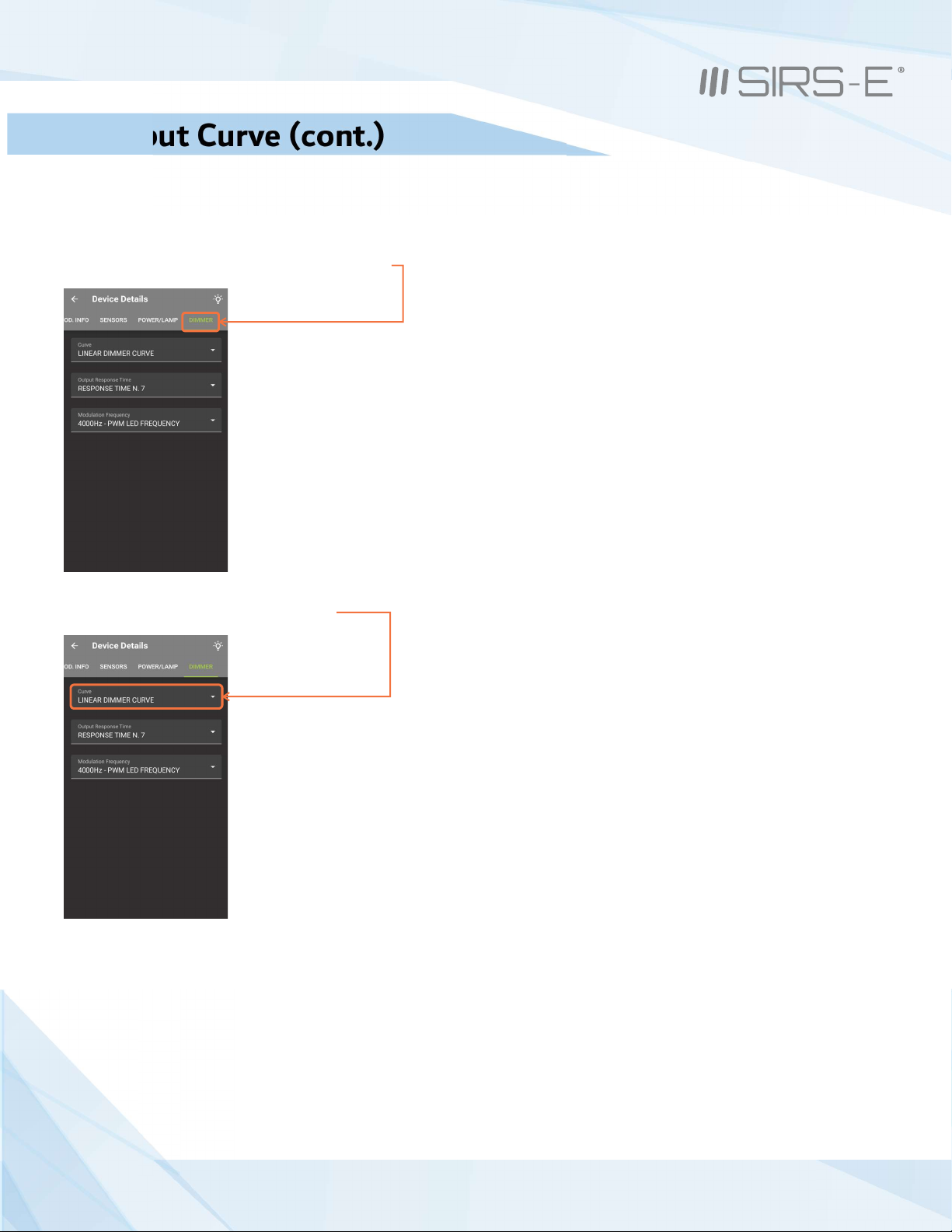
8.2 Output Curve (cont.)
For Linear:
1. Navigate and tap on “Dimmer” category tab.
2. Navigate and tap on the “Curve” menu.
* The RDM configuration example shown depicts the user interface from the
DMXcat controller by City Theatrical. Other software and controllers will
show a different set of steps or layouts, but the idea is the same.
14
3307 West Street Rosenberg, TX 77471 USA - (281) 324-0908
Copyright © 2006-2021 SIRS Electronics Inc. All Rights Reserved P ™ PCB Instruction Manual
ILOTINO
Updated 12/2021. Rev 2.8

3. A drop down menu will appear, from here you can select the desired Curve Style.
4. Once the Dimmer Curve Style has been selected, the selection will be automatically saved in the device’s memory.
8.2 Output Curve (cont.)
For Linear: (Cont.)
* The RDM configuration example shown depicts the user interface from the
DMXcat controller by City Theatrical. Other software and controllers will
show a different set of steps or layouts, but the idea is the same.
15
3307 West Street Rosenberg, TX 77471 USA - (281) 324-0908
Copyright © 2006-2021 SIRS Electronics Inc. All Rights Reserved P ™ PCB Instruction Manual
ILOTINO
Updated 12/2021. Rev 2.8

8.3 Output Frequency
Output Frequency
The P ™ PCB has 9 frequency output modes to select from:
ILOTINO
1kHz, 1.5kHz, 2kHz, 2.5kHz, 3kHz, 3.5kHz, 4kHz, 4.5kHz, and 5.2kHz.
These modes can be accessed by setting the onboard DIP switches in the following way:
(Be sure to perform all connections prior to turning on the power supply. )
1. Connect the input power from the power supply
2. Connect the LEDs to the output wire to board connectors
3. Connect the DMX input to the connectors or achieve a wireless connection with the P CRMX™ PCBILOTINO
4. Switch ON the power supply
5. The green indicator LED will turn on steady
6. Switch DIP switch 10 to the ON position
For 1-5.2kHz:
. 7. Navigate and tap on “Dimmer” category tab
* The RDM configuration example shown depicts the user interface from the
DMXcat controller by City Theatrical. Other software and controllers will
show a different set of steps or layouts, but the idea is the same.
16
3307 West Street Rosenberg, TX 77471 USA - (281) 324-0908
Copyright © 2006-2021 SIRS Electronics Inc. All Rights Reserved P ™ PCB Instruction Manual
ILOTINO
Updated 12/2021. Rev 2.8

8.3 Output Frequency (cont.)
For 1-5.2kHz: (Cont.)
.8. Navigate and tap on “Modulation Frequency Menu” category tab
9. A drop down menu will appear, from here you can select the desired Output Frequency
* The RDM configuration example shown depicts the user interface from the
DMXcat controller by City Theatrical. Other software and controllers will
show a different set of steps or layouts, but the idea is the same.
17
3307 West Street Rosenberg, TX 77471 USA - (281) 324-0908
Copyright © 2006-2021 SIRS Electronics Inc. All Rights Reserved P ™ PCB Instruction Manual
ILOTINO
Updated 12/2021. Rev 2.8

8.3 (cont.)Output Frequency
For 1-5.2kHz: (Cont.)
10. Once the Output Frequency has been selected, the selection will be automatically saved in the device’s memory.
8.4 Bit Mode Selection
Bit Mode Selection
The P ™ PCB has 10 bitmode channel configurations to select from: 1,2,3,4, or 5 channels 8 bit and 1,2,3,4 or 5
ILOTINO
channels 16 bit
These modes can be accessed by setting the onboard DIP switches in the following way:
(Be sure to perform all connections prior to turning on the power supply.)
1. Connect the input power from the power supply
2. Connect the LEDs to the output wire to board connectors
3. Connect the DMX input to the connectors or achieve a wireless connection with the P CRMX™ PCB
ILOTINO
4. Switch ON the power supply
5. The green indicator LED will turn on steady
6. Switch DIP switch 10 to the ON position
7. Follow the same steps used to change the other RDM functions: To select the bit mode, use the
“DMX Personality menu”
* The RDM configuration example shown depicts the user interface from the
DMXcat controller by City Theatrical. Other software and controllers will
show a different set of steps or layouts, but the idea is the same.
18
3307 West Street Rosenberg, TX 77471 USA - (281) 324-0908
Copyright © 2006-2021 SIRS Electronics Inc. All Rights Reserved P ™ PCB Instruction Manual
ILOTINO
Updated 12/2021. Rev 2.8

DMX Failure Settings
The P ™ PCB has 3 reaction modes in the event of a DMX input failure: Last Value, On, and Test.
ILOTINO Hold Full
These modes can be accessed by setting the onboard DIP switches in the following way:
(Be sure to perform all connections prior to turning on the power supply.)
1. Connect the input power from the power supply
2. Connect the LEDs to the output wire to board connectors
3. Connect the DMX input to the connectors or achieve a wireless connection with the P CRMX™ PCB
ILOTINO
4. Switch ON the power supply
5. The green indicator LED will turn on steady
6. Switch DIP switch 10 to the ON position
7. Follow the same steps used to change the other RDM functions: To select DMX failure setting, use the “DMX Fail
Mode” menu
- Scene 1: Hold Last Value - Scene 2: Full On - Scene 3: Test (5% of all Channels)
10. DMX Failure Settings 8.5 DMX Failure Settings
Response Time
The P ™ PCB has 5 response time modes for the DMX signal input:
ILOTINO
These modes can be accessed by setting the onboard DIP switches in the following way:
(Be sure to perform all connections prior to turning on the power supply.)
1. Connect the input power from the power supply
2. Connect the LEDs to the output wire to board connectors
3. Connect the DMX input to the connectors or achieve a wireless connection with the P CRMX™ PCB
ILOTINO
4. Switch ON the power supply
5. The green indicator LED will turn on steady
6. Switch DIP switch 10 to the ON position
7. Follow the same steps used to change the other RDM functions: To select the response time of the device,
use the “Output Response Time” menu:
1 & 2 = Fast 3 = Normal 4 & 5 = Slow
10. DMX Failure Settings 8.6 ime Response T
19
3307 West Street Rosenberg, TX 77471 USA - (281) 324-0908
Copyright © 2006-2021 SIRS Electronics Inc. All Rights Reserved P ™ PCB Instruction Manual
ILOTINO
Updated 12/2021. Rev 2.8

8.7 Default Settings
Default Settings
The P ™ PCB can revert back to it’s original factory configurations with a simple command from an RDM controller.
ILOTINO
The procedure to achieve factory default settings are as follows:
1. Connect the input power from the power supply
2. Connect the LEDs to the output wire to board connectors
3. Connect the DMX input to the connectors or achieve a wireless connection with the P CRMX™ PCB
ILOTINO
4. Switch ON the power supply
5. The green indicator LED will turn on steady
6. Switch DIP switch 10 to the ON position
Restore Factory Defaults:
7. Navigate and tap on “Prod. INFO” category tab.
* The RDM configuration example shown depicts the user interface from the
DMXcat controller by City Theatrical. Other software and controllers will
show a different set of steps or layouts, but the idea is the same.
20
3307 West Street Rosenberg, TX 77471 USA - (281) 324-0908
Copyright © 2006-2021 SIRS Electronics Inc. All Rights Reserved P ™ PCB Instruction Manual
ILOTINO
Updated 12/2021. Rev 2.8
This manual suits for next models
1
Table of contents
Other SIRS-E Media Converter manuals


Popular Media Converter manuals by other brands


StarDental
StarDental DentalEZ Titan Blis-sonic K 264564 instruction manual

CYP
CYP CDB-6HR Operation manual

Net Optics
Net Optics GIGABIT TX TO SX TAP CVT-GCU/SX installation guide

Transition Networks
Transition Networks SBFTF1011-120 user guide

Lenz Elektronik
Lenz Elektronik Digital Plus manual

Texas Instruments
Texas Instruments LM5181-Q1 user guide


