SITECNA FR 12 Series Manual

14
41
35
a
40
35
13
15
20
11b 11a
14
INOX VERSION
FILTER ELEMENT 5M FILTER ELEMENT 25M
AUTOMATIC DRAIN MANUAL DRAIN
FILTER ELEMENT 5M FILTER ELEMENT 25M
AUTOMATIC DRAIN MANUAL DRAIN
ALUMINUM VERSION
25
36
37
38
14
41
35
a
Filter, Regulator & Filter Regulators
Series 12, 16 - 3/4”, 1”NPT
Installation, Regulation and
Maintenance Instructions
Sitecna Srl a Socio Unico
Via G. Di Vittorio, 22
20068 Peschira Borromeo
Milano - ITALY
Tel. +39 025475482
Fax +39 0255303713
E-mail [email protected]
Web www.sitecna.eu
SIL
IEC 61508
Safety Integrity Level IP66
LABEL
HOW TO ORDER
0= None
1= 0.2-2 bar
2= 0.2-4 bar
3= 0.4-8 bar
4= 0.4-10 bar
5= 0.4-12 bar
04= 1/4” NPT
06= 3/8” NPT
08= 1/2” NPT
12= 3/4” NPT
16= 1” NPT
24= 1” 1/2”NPT*
32= 2”NPT*
TYPE
FILTER ELEMENT
PRESSURE GAUGE
OPTION
MATERIAL
DIAPHRAGM & SEALS MATERIAL
SIZE RANGE ACCESSORIES
F= Filter
FR= Filter Regulator
R= Regulator
0= None
1S= AISI304 or AISI316 case
(SS316 connection)
1B= AISI304 case (brass connect.)
00= None
05= No relieving
06= 1/4” gauge port
07= Automatic drain
56= No relieving
1/4” gauge port
57= No relieving
Automatic drain
67= 1/4” gauge port
Automatic drain
SS= 316-316L Stainless steel
AL= Copper free aluminum alloy
FK= FKM ( WT-25° +90°C )
NB= NBR ( WT-20° +80°C )
LT= EPDM ( WT-40° +80°C )
FL= Special compound (WT-55°+90°C)
HN= HNBR (WT -55 +90°C)
0= None
2= SS bracket kit
3= Panel nut&handwheel
4= Customised Tag
5= SS bracket kit +
nut&handwheel
6= SS bracket kit+custom.Tag
Specials
FR 06 3 1 1S 5 6 SS FK 2 # #
For technical information refer to the
corresponding technical data sheet
* only for filters
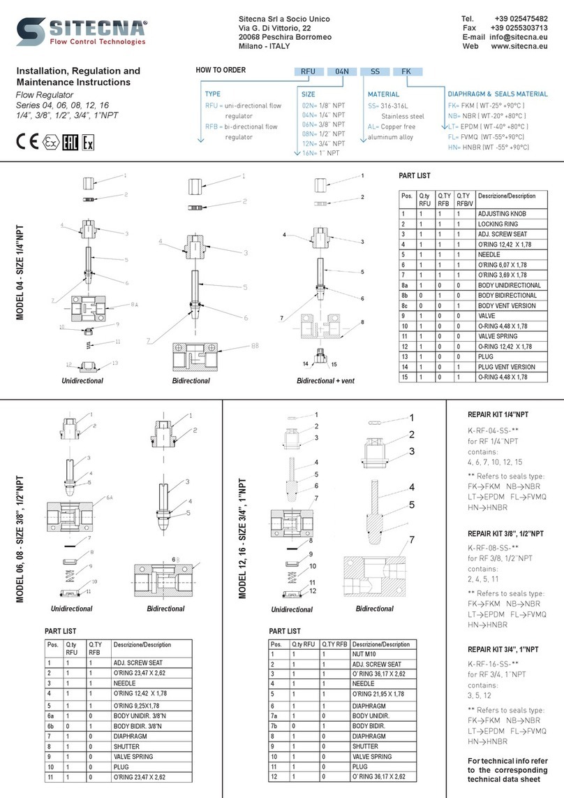
PART LIST
REPARING KIT
Contains: 8, 10, 14, 16, 17, 25, 27, 28, 31, 33, 38, 40, 41
+ for 5 micron FR & F: 21a, 21b
+ for 25 micron FR & F: 21b
Pos. Q.ty
R
Q.ty
FR
Q.ty
F
Descrizione/Description
1 1 1 0 ADJUSTMENT SCREW
2 1 1 0 LOCK ADJUSTMENT NUT
3 1 1 0 BONNET
4 1 1 0 UPPER SPRING SEAT
5 1 1 0 ADJUSTMENT SPRING
6 1 1 0 LOWER SPRING RESET
7 1 1 0 SLIP RING
8 1 1 0 DIAPRAGHM
9 1 1 0 VALVE SEAT
10 1 1 0 O’RING VALVE SEAT (ONLY FOR
RELIEVING) 5,32X2,62
11a 1 1 0 FR & R BODY
11b 0 0 1 F BODY
12 1 1 0 SIPHON
13 2 2 2 CONNECTION
14 2 2 2 O’RING 37,82X1,78
15 2 2 2 BRACKET
16 1 1 0 VALVE STEAM
17 1 1 0 O’RING 3,69x1,78
18 1 1 0 VALVE
19 1 1 0 VALVE SPRING
20 0 1 1 FILTER ELEMENT SUPPORT
21a 0 2 2 FILTER ELEMENT 5 MICRON
21b 0 2 2 FILTER ELEMENT 25 MICRON
22 0 1 1 FILTER ELEMENT RING
23 0 1 1 FILTER ELEMENT PLUG
24 0 1 1 FILTER ELEMENT SCREW
25 0 1 1 O’RING BOWL 88,58x2,62
26a 0 1 1 MANUAL DRAIN BOWL
26b 0 1 1 AUTOMATIC DRAIN BOWL
27 0 1 1 BENZIN
28 0 1 1 O’RING DRAIN 3,69x1,78
29 0 1 1 MANUAL DRAIN
30 0 1 1 AUTOMATIC DRAIN
31 0 1 1 O’RING AUTO DRAIN 9,92 X 2,62
32 0 1 1 AUTOMATIC DRAIN SEAT
33 0 1 1 O’RING AUTO DRAIN 15,54X2,62
34 0 1 1 AUTOMATIC DRAIN SEAT
35 8 8 8 SCREW M5x16 DIN 912 A2
36 1 0 0 REGULATOR BOTTOM
37 1 0 0 REGULATOR VALVE SEAT
38 1 0 0 O’RING 32,99X2,62
39 0 0 1 FILTER TOP
40 0 0 1 O’RING 61,62x2,62
41 1 1 0 O’RING VALVE 18,72X2,62
INOX VERSION
Regulator Filter Regulator Filter
0= None
1= 5 micron
2= 25 micron
3= 40 micron
4= coalescing*
5= 3 micron
for 1/4”, 3/8”,
1/2”NPT

Automatic Drain
Non Relieving
1.INTRODUCTION
Throughout this manual there are a number of HAZARD
WARNINGS that must be read and adhered to in order to
prevent possible personal injury and/or damage to equi-
pment. Three signal work “DANGER”, “WARNING” and
“CAUTION” are used to indicate the severity of a hazard,
and are preceded by the safety alert symbol.
Danger Denotes the most serious hazard and is
used when serious injury or death WILL result from misuse
or failure to follow specic instructions.
Warning Used when serious injury or death MAY
result from misuse or failure to follow specic instructions.
Caution Used when injury or product/equipment
damage may result from misuse or failure to follow specic
instructions.
Caution It is the responsibility and duty of
Warning all personnel involved in the installation,
Danger operation and maintenance of the equi-
pment on which this device is used, to fully understand the
procedures by which hazards can be avoided.
The compatibility of the product is the responsibility of
the person who designs the equipment or decides its
specications.
Only personnel with appropriate training should operate
machinery and equipment.
Do not service or attempt to remove the machinery or
equipment until safety is conrmed.
2.DESCRIPTION
Before you can feed a plant with a gaseous uid, it must be
processed to remove contaminants such as water and oil
particles, dirt and is also necessary to reduce the pressure
to the level required by the equipment downstream.
• Filters are designed to remove airborne solid and liquid
contaminants which may plug small orices and hinder
performance or cause excessive wear and premature
equipment failure.
• Regulators provide controlled, consistent air pressure as
required for specic pneumatic equipment connected to
the air system.
• Filter/regulators are designed to remove airborne solid and
liquid contaminants which may plug small orices and
hinder performance or cause excessive wear and prema-
ture equipment failure. In addition to ltration the regula-
tors portion provides controlled, consistent air pressure
as required for specic pneumatic equipment connected
to the air system
3. OPERATION
In these devices, the main spring (5) exerts a force on a
diaphragm assembly (6,7,8,9,10). This force can be adju-
sted by turning the adjustment screw (1). By readjusting
the main spring, the regulator valve assembly (16,17,18,
41) is pushed down and the seat of the lower seal is rele-
ased, while the front side of the adjusting piston continues
to be sealed by the element sealing in the diaphragm. This
allows the ow from the pressure to the processing lines for
the supply and exhausting of the system. Small pressure
uctuations can be compensated by slight movements of
the piston adjustment and changes of the ow on the lower
valve seat. If the pressure on the line of work exceeds the
set pressure of work, this generates a force on the lower
side of the diaphragms that pushes the diaphragm upwards,
the air then ows over the sealing element in the diaphragm
and through a light of drain on the body of the compressed
air regulator.
AISI316 and Aluminium Filter, Regulator, Filter-regulator - 3/4”, 1”NPT
INSTALLATION, REGULATION & MAINTENANCE INSTRUCTIONS
Fig.2 Regulator
4. PNEUMATIC DIAGHRAM Fig.3 Filter
Automatic Drain
Relieving
Manual Drain
Non Relieving
Manual Drain
Relieving
Relieving
Non
Relieving
Manual
Drain
Automatic
Drain
5. TECHNICAL FEATURES
Medium: compressed air or inert gases, ltered, lubricated or not
Port thread: 3/4” - 1”NPT
Gauge connection: 1/8” – 1/4”NPT
for FR & F: 5, 25, 40 micron, coalescing (only F)
Max inlet pressure: 25 bar (for aluminum version)
30 bar (for AISI 316 version)
16 bar (only for F, FR with automatic drain)
Drain valve: manual or automatic
Flow rate: FR,R:
11500 dm3/min CV=11.5(P.in 10bar - P.reg.6bar - .Δ P 1bar)
F12: 7500 dm3/min CV=7,10 (P.in 10bar - delta P. 0.35bar)
F12: 10000 dm3/min CV=10,0 (P.in 10bar - delta P. 0.35bar)
Pressure range: 0.2/2, 0.2/4, 0.4/8, 0.4/10, 0.4/12 bar
Materials: Body SS316L or aluminum alloy
Filter element SS316
Internal parts stainless steel
MATERIAL TEMPERATURE
DIAPHRAGM SEALS TRANSPORT STORAGE OPERATING
NBR NBR -20°C...+80°C -20°C...+80°C -20°C...+80°C
FKM FKM -25°C...+90°C -25°C...+90°C -25°C...+90°C
EPDM EPDM -40°C...+80°C -40°C...+80°C -40°C...+80°C
FVMQ FVMQ -55°C...+90°C -55°C...+90°C -55°C...+90°C
HNBR HNBR -55°C...+90°C -55°C...+90°C -55°C...+90°C
6.TRANSPORTATION & STORAGE
The preferred storage location is a clean, dry and protected
warehouse. If the components have to be stored outside,
precautions should be taken to keep valves clean and dry.
For storage temperatures, refer to the table in paragraph
“TECHNICAL FEATURS”.
To avoid contamination of impurities during the storage period,
don’t remove thread protection caps; remove them just before
the installation phase.
7. INSTALLATION
Warning Before performing any work, read this ma-
nual and study all gures. Assure yourself that you understand
and you can do what is required in each step. Failure to follow
these instructions may affect quick release valve operation and
may result in exposure to personal injury.
Before installing the valve, set and block the machine or equi-
pment in a secure position; close the air shutoff valve and
exhaust air from air lines and disconnect all electrical power.
• Upstream of lubricators and cycling valves
• As close as possible to the air supply when used as a main
line lter
•As close as possible to the device being serviced when used as
a nal lter
• Caution In the version with automatic drain and
with hazardous area medium but compatible with the mate-
rials, you must remember that the device is designed with
allowable leakage. In the cases, it is necessary to provide for
the conveyance of the discharge in safe area. No responsi-
bility will be charged to SITECNA to unsafe use.
8. MOUNTING
• Vertically (bowl down),
• With air ow in direction of arrow on body,
• Connect piping to proper ports using pipe thread sealant on
male threads only. Do not allow sealant to enter the unit.
• Install a pressure gauge or plug the gauge ports. Gaugeports
can also be used as additional outlets for regulated air
9. TESTING
• Before applying inlet pressure to lter/regulator, turn adjust-
ment (1) counterclockwise to remove all force on regulating
spring (5).
• Apply inlet pressure, then turn adjustment (1) clockwise to
increase and counterclockwise to decrease outlet pressure
setting.
• Always approach the desired pressure from a lower pressure.
When reducing from a higher to a lower setting, rst reduce
to some pressure less than thatdesired, then bring up to the
desired pressure.
Caution With non-relieving lter/regulators, make
pressure reductions with some air ow in the system. If
made under no ow (dead-end) conditions, the lter/regula-
tor will trap the over-pressure in the downstream line.
• Once required pressure is achieved tighten locknut (2) to
lock setting.
10. MAINTENANCE
Warning Before performing any work, read this
manual and study all gures. Assure yourself that you un-
derstand and can do what is required in each step. Failure
to follow these instructions may affect quick release valve
operation and may result in exposure to personal injury.
Before uninstalling the valve, set and block the machine or
equipment in a secure position; close the air shutoff valve
and exhaust air from air lines; disconnect electrical power.
• Filter/regulator can be disassembled without removal from
air line.
• Shut off inlet pressure. Reduce pressure in inlet and outlet
lines to zero.
• Turn adjustment screw fully counter clockwise.
• Disassemble in general accordance with the item numbers
on exploded view. Do not remove the drains unless repla-
cement is necessary. Remove and replace drains only if
they malfunction.
A.Ordinary maintenance
Caution The FR, F and R should be periodically
checked for proper functioning:
• Clean the FR, F and R from impurities and dirt;
• Visually check of the integrity of the body and cup of FR,
F and R;
• Check that there aren’t leakages;
• Check the correct functionality of the FR, F and R;
• For manual drain models, regularly open drain to expel
accumulated liquids. Keep liquids below lter element (21)
• At approximately 6 month intervals it is advisable to remove
the bowl assembly by removing the securing screws (27)
and unscrewing the lter element (21) for inspection;
• Clean or replace lter element when dirty.
B. Troubleshooting
Issue
Possible Cause
Fixes
leakage between
body and lower
cup for FR, F, R
Seal damage replace the o-ring (25) or contact
SITECNA technical support for more
information
no adjustment
pressure for FR
and R
Diaphragm
or valve
damaged
replace diaphragm assembly (6,7,8, 9,
10, 11) and valve assembly (16, 17,18)
or contact SITECNA technical support
for more information
pressure drop
reaches or
exceeds 10psig
(0.7bar)
dirty lter
element
replace lter element (21) or contact
SITECNA technical support for more
information
C. Assembly
• Lubricate threads and nose of adjusting screw (1) at regu-
lar intervals with suitable grease.
•
Lubricate seals (17) with light coat of good quality grease.
• Assemble the unit as shown on the exploded view.
11. MARKING ACORDING TO 2014/34/UEAtex
For using these equipment in potentially explosive atmo-
spheres, it is recommended - for the installation and the
maintenance operation - to use tools and instruments that
can produce only a single spark (for instance: screwdrivers,
spanners). Avoid use of tools that can produce sparks like
disk saw or grinder
Action must be taken to put to earth the units through a su-
itable connection, checking that all the metal components
(ttings and pipe line) have to be equitable potential.
Equipment have to be installed in the corresponding zone
according to the marking.
II 2G Ex h IIC T6/T5 Gb X
II 2D Ex h IIIC T85°C/T100°C Db X
After replacing the FR, F and R “TESTING” phase
Fig.1 Filter Regulator
SIL
IEC 61508
Safety Integrity Level IP66
NOTE
Warning As option is available an “Anti-tamper sy-
stem” to avoid the un-authorized modication of the setting.
This option is mandatory for safety related applications.
NOTE: special conditions for safe use (X conditions)
Before performing any work, read this manual and assure
yourself you understand. X at the end of ATEX sobstitutes
T amb for series VB, DP, VSR, RF, LK, SCLP, T F, FLGSS, VP,
SLHF, SLVP, SLSC, PV. T amb depeends on used seals,
based on the following correspondance:
NBR=-20°C...+80°C, FMK=-25°C...+90°C,
EPDM= -40°C...+80°C, FVMQ & HNBR= -55°C...+90°C

Sitecna Srl a socio unico
Via G. Di Vittorio, 22
20068 Peschiera Borromeo
Milano - Italy ( Europe)
Milano –Italy ( Europe)
P.IVA/C.FISC. 08973090155
NR MECC. MI253803
C.C.I.A.A. 1259759
Dichiarazione di conformità UE
In accordo con la Direttiva Europea 2014/34/UE
EU-Declaration of Conformity
In accordance with Directive 2014/34/EU
Noi, Sitecna Srl, dichiariamo che i seguenti prodotti / Sitecna Srl declares that the following equipment:
Product
mod.
Product
mod.
Product
mod.
Filter
F…
Volume Booster
VB…
Flow regulator
RFB…, RFU…
Regulator
R…
Control spool valve
DP…
Glass tube flowmeter
FLGSS…
Filter Regulator
FR…
Quick exhaust valve
VSR…
Vacuum pump
ST-VP…
Back Pressure valve
BP
Lock-up valve
LK…
Silencer
SLHF…, SLVP…, SLSC…
2 ways switching valve
SV…
Overload protector
SCLP…
Dust excluder
PV…, PVSL…
3 ways switching valve
S3…
Tee Filter
TF
Pressure gauge
MBSS…, MBS6…, MBSN…
Sono conformi alla normativa di armonizzazione dell’Unione / They comply with the Union harmonization legislation:
Direttiva 2014/34/UE ATEX
Direttiva 2014/34/UE del Parlamento europeo e del Consiglio, del 26 febbraio 2014,
concernente l’armonizzazione delle legislazioni degli Stati membri relative agli
apparecchi e sistemi di protezione destinati a essere utilizzati in atmosfera
potenzialmente esplosiva (rifusione) Testo rilevante ai fini del SEE.
Directive 2014/34/EU of the European Parliament and of the Council of 26 February
2014 on the harmonisation of the laws of the Member States relating to equipment and
protective systems intended for use in potentially explosive atmospheres (recast) Text
with EEA relevance.
Secondo le seguenti Norme di riferimento / As per folowing reference Normative Documents:
EN ISO 80079-36:2016
Atmosfere esplosive - Apparecchi non elettrici per atmosfere esplosive -
Metodo di base e requisiti
Explosive atmospheres - Non-Electrical equipment for explosive atmospheres - Basic
method and requirements
EN ISO 80079-37:2016
Atmosfere esplosive - Apparecchi non elettrici per atmosfere esplosive –
Tipo di protezione non elettrica per sicurezza costruttiva "c", per controllo della sorgente
di accensione "b", per immersione in liquido "k"
Explosive atmospheres - Non-Electrical equipment for explosive atmospheres - Non-
electrical type of protection constructional safety ''c'', control of ignition sources ''b'', liquid
immersion ''k''
N 1127-1:2011
Atmosfere esplosive - Prevenzione dell’esplosione e protezione contro l’esplosione -
Concetti fondamentali e metodologia
Explosive atmospheres - Explosion prevention and protection - Basic concepts and
methodology
Ai sensi della Direttiva 2014/34/EU, i prodotti sopra indicati riportano la seguente marcatura / According to the Directive 2014/34/EU,
above mentioned products reports the following marking:
II 2G Ex h IIC T6/T5 Gb X
II 2D Ex h IIIC T85°C/T100°C Db X
Inoltre, ai sensi della direttiva 2014/34/UE, i prodotti sopra menzionati sono oggetto, per gli aspetti relativi sia alla progettazione sia alla fabbrica-
zione, al controllo interno di fabbricazione (Allegato VIII –Modulo A). Ref 557/Ex-Ab 3213/20 c/o N° 0035 TÜV Rheinland.
In conformity to Directive 2014/34/EU, the afore mentioned equipment, regarding their design and production, are object to internal manufacturing
check (Attachment VIII –Module A). Ref 557/Ex-Ab 3213/20 c/o N° 0035 TÜV Rheinland.
La presente dichiarazione di conformità è rilasciata sotto
la responsabilità esclusiva del fabbricante.
This declaration of conformity is issued under exclusive
responsibility of the manufacturer.
Milan, 20/05/2020
Davide Matteo De Corrado
Managing Director
Trace No: xxxx
This manual suits for next models
7
Other SITECNA Controllers manuals
