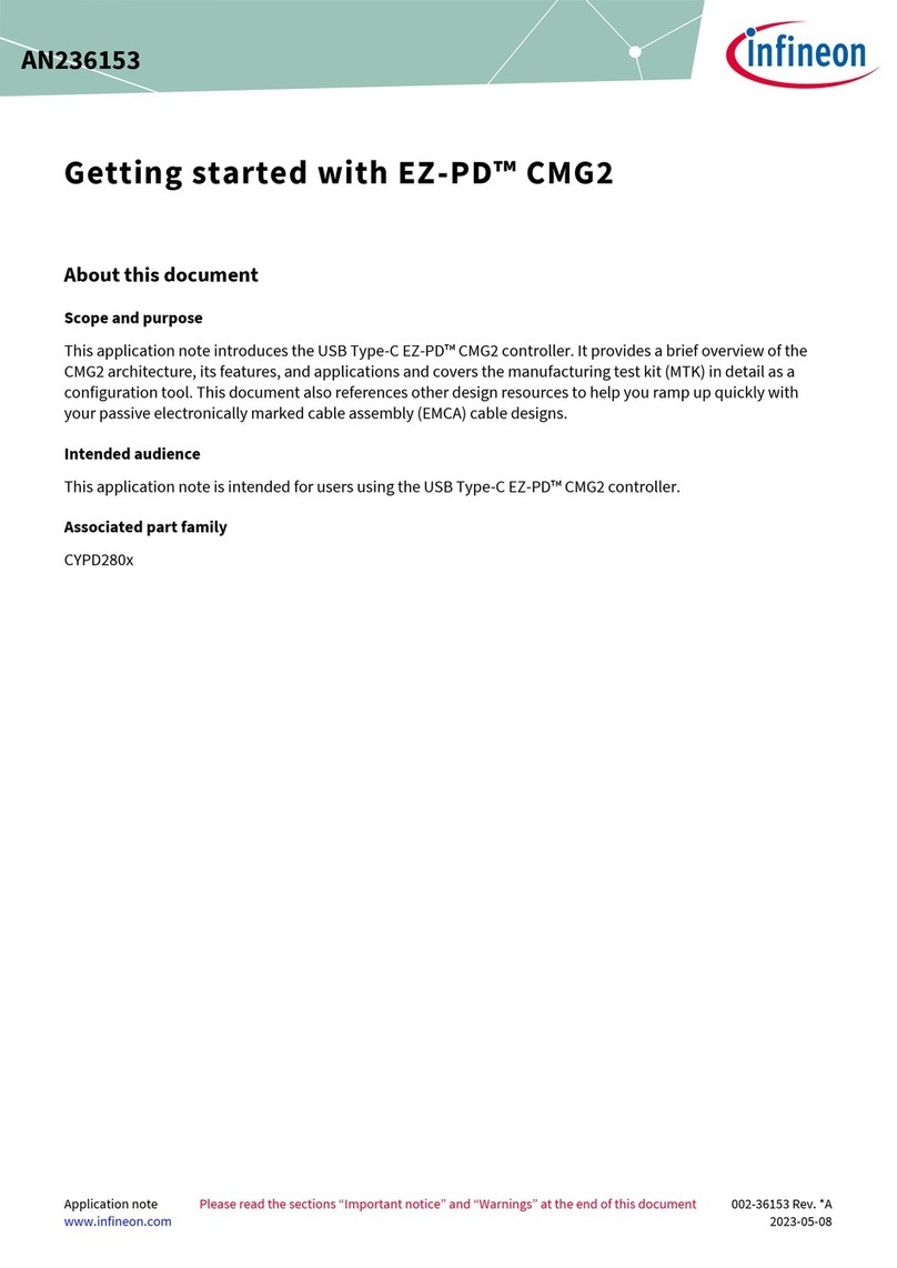
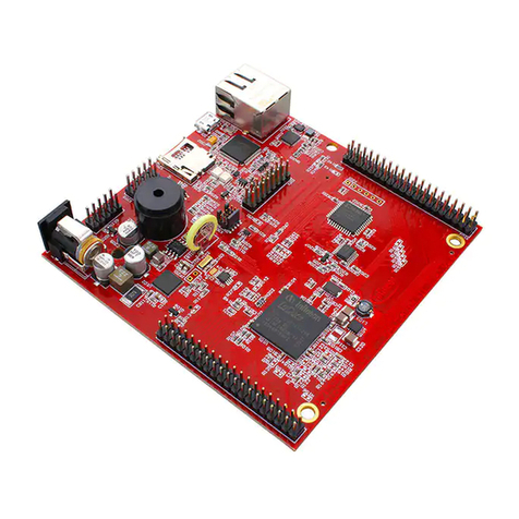
Infineon iMOTION IRDM983-025MB User manual


This manual suits for next models
1
Table of contents
Other Infineon Controllers manuals

Infineon
Infineon ICE2QS03G Installation and operating instructions
Infineon
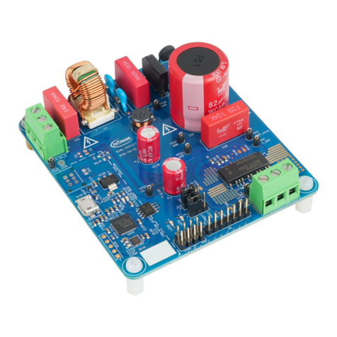
Infineon EVAL-IMI111T User manual

Infineon
Infineon ICE2HS01G Installation and operating instructions
Infineon
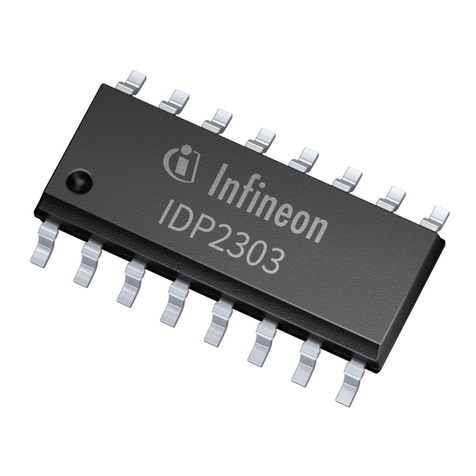
Infineon IDP2303 Guide
Infineon
Infineon XDPL8210 User manual
Infineon
Infineon CoolSET-F3R ICE3BRXX65JZ series Guide
Infineon
Infineon TLD5098EP User manual
Infineon
Infineon TLD5099EP User manual

Infineon
Infineon NAC1080 User manual

Infineon
Infineon OPTIREG TLF30681QVS01 User manual

Infineon
Infineon CPU-42A-V1 User manual

Infineon
Infineon IMC300A Series User manual

Infineon
Infineon XDPL8218 Guide
Infineon
Infineon iMOTION EVAL-IMM101T Series User manual
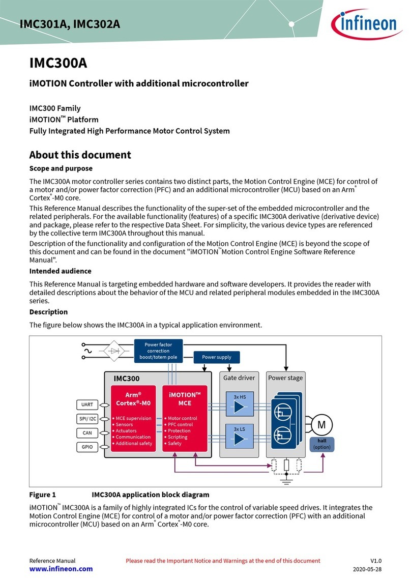
Infineon
Infineon IMC300A Series User manual

Infineon
Infineon XDPP1100 Product manual

Infineon
Infineon XDPP1100 User manual
Infineon
Infineon BTN7030-1EPA User manual

Infineon
Infineon 82C900 Installation and operating instructions

Infineon
Infineon NAC1080 Guide
Popular Controllers manuals by other brands
Mitsubishi Electric
Mitsubishi Electric MELSEC iQ-R C user manual

Solem
Solem BL-IS Quick installation guide

Zaxcom
Zaxcom ZFR200 user manual
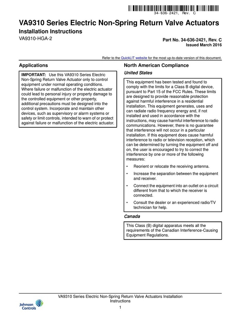
Johnson Controls
Johnson Controls VA9310 Series installation instructions

Moxa Technologies
Moxa Technologies ioPAC 8500 series Hardware user manual

Emerson
Emerson Bettis G01 Series Disassembly and Reassembly
Microchip Technology
Microchip Technology PICtail Plus MCP25625 user guide

Metso
Metso neles EJ Series Installation maintenance and operating instructions
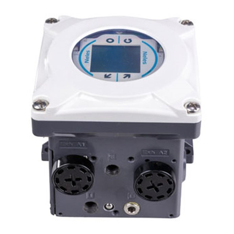
Metso
Metso NELES NDX Series Installation maintenance and operating instructions
SMC Networks
SMC Networks JXC9H Operation manual
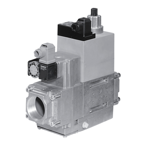
Dungs
Dungs GasMultiBloc MB-D B01 Series instructions

IPCO
IPCO STUDIO 3000 operating instructions
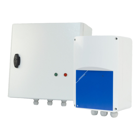
Sentera Controls
Sentera Controls STVS1 Series Mounting and operating instructions
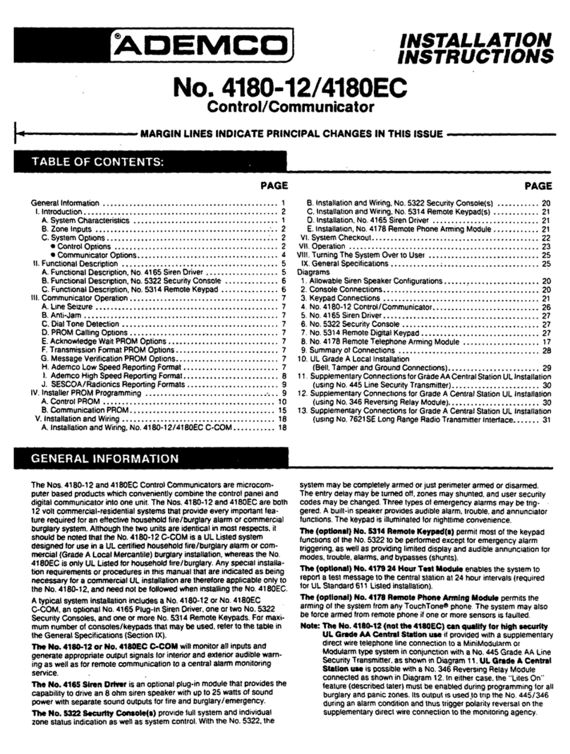
ADEMCO
ADEMCO 4180-12 Installation instructions manual

Holman
Holman CLXRGB60 user guide

IFM
IFM EC2121 System manual
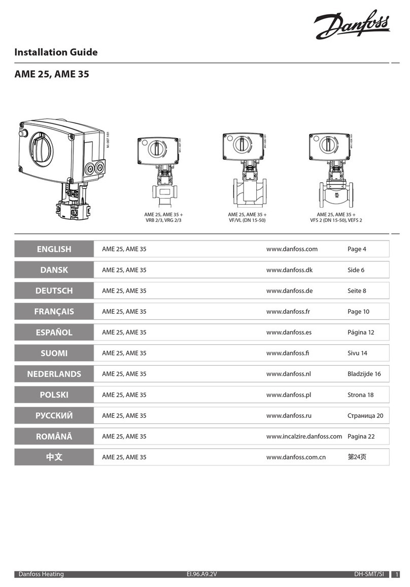
Danfoss
Danfoss AME 25 installation guide
Mitsubishi Electric
Mitsubishi Electric MELSERVO MR-J5-G-N1 Series user manual
