SK L Series User manual

Škrlj d.o.o., tel.: ++386 (0)5 36 43 500 – fax: ++386 (0)5 36 43 525 www.sk-group.biz - [email protected]
matina št.: 5559839 – davna št.: 94136408
NAV_PSL_ 2008/07_UK_v4
PNEUMATIC PRESSES
SERIES
L
PSP_PST_ 21/29/42/55
OPERATION AND MAINTENANCE MANUAL

NAV_PSL_ 2008/07_UK_v4
2
TABLE OF CONTENTS:
1 INTRODUCTION ........................................................................................................................... 4
2 PURPOSE OF PNEUMATIC PRESS ............................................................................................ 4
3 GUARANTEE ................................................................................................................................ 4
4 HEALTH AND SAFETY................................................................................................................. 5
4.1 Meaning of the symbols....................................................................................................... 5
4.2 GENERAL SAFETY PRECAUTIONS .................................................................................... 5
4.3 SAFETY DEVICES................................................................................................................. 6
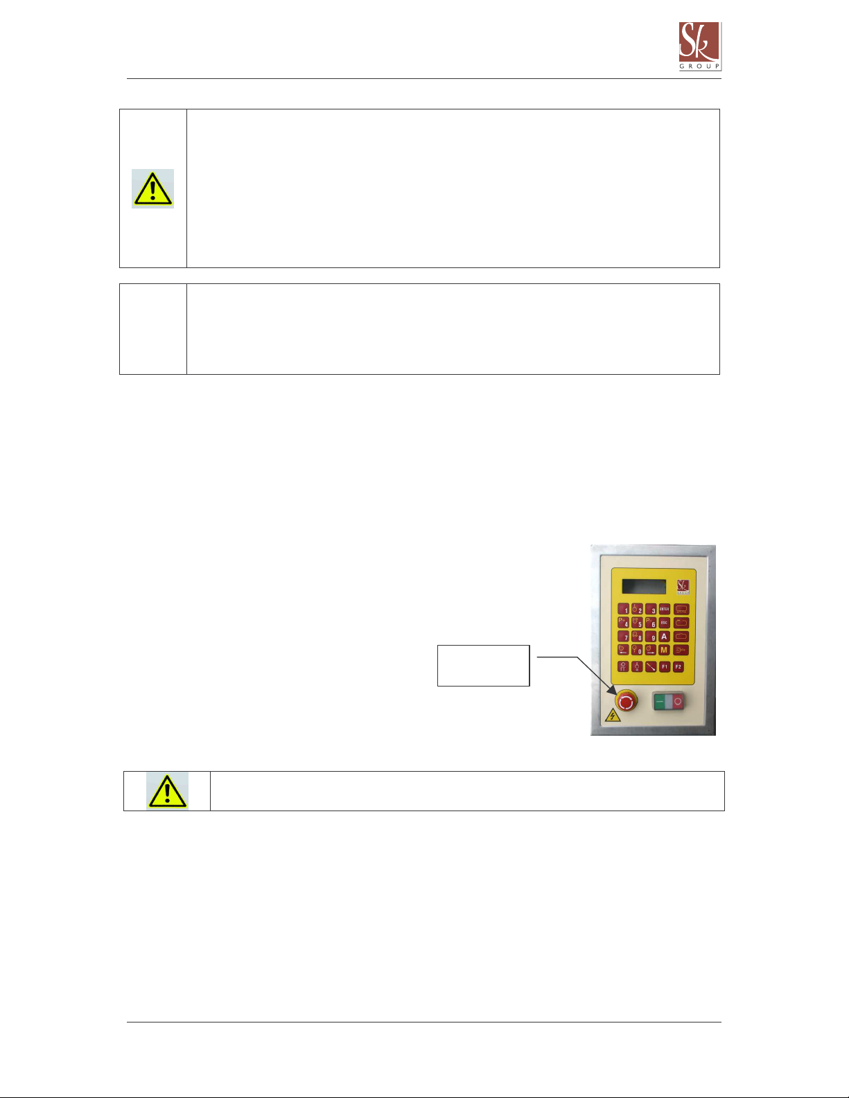
4.3.1 Emergency STOP button................................................................................................. 6
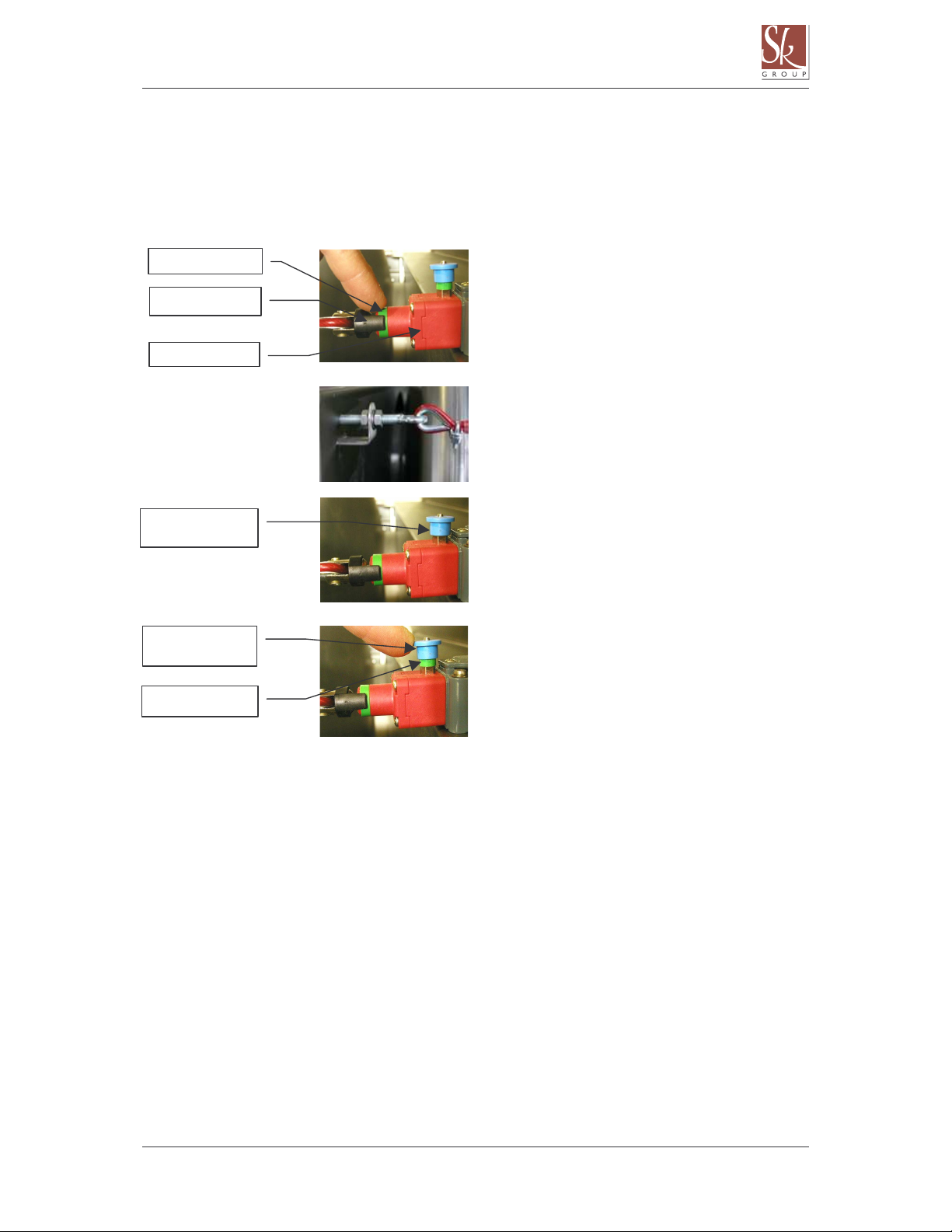
4.3.2 Safety cord ...................................................................................................................... 7
4.3.3 Protection against overpressure in the drum ................................................................... 8
4.3.4 Overload relays ............................................................................................................... 8
5 PRESS TRANSPORT AND SETTING UP..................................................................................... 9
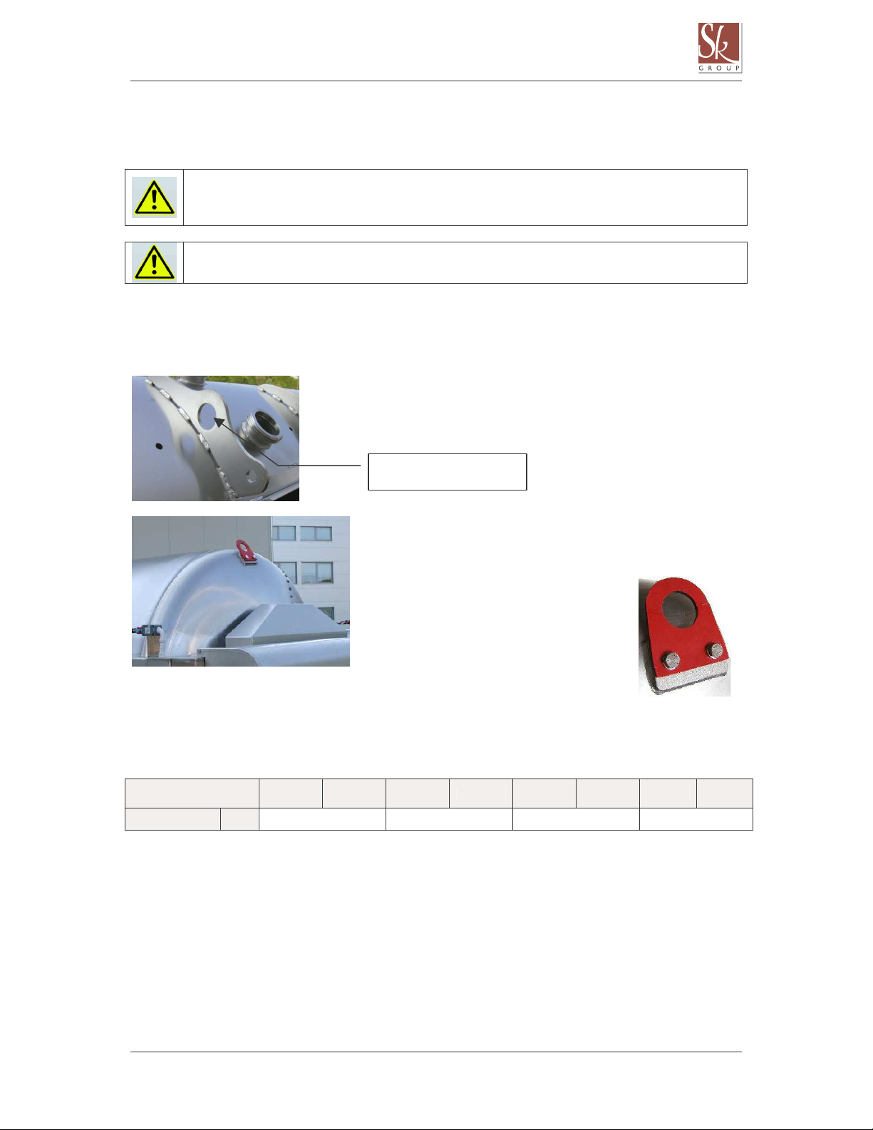
5.1 Transport of the press.......................................................................................................... 9
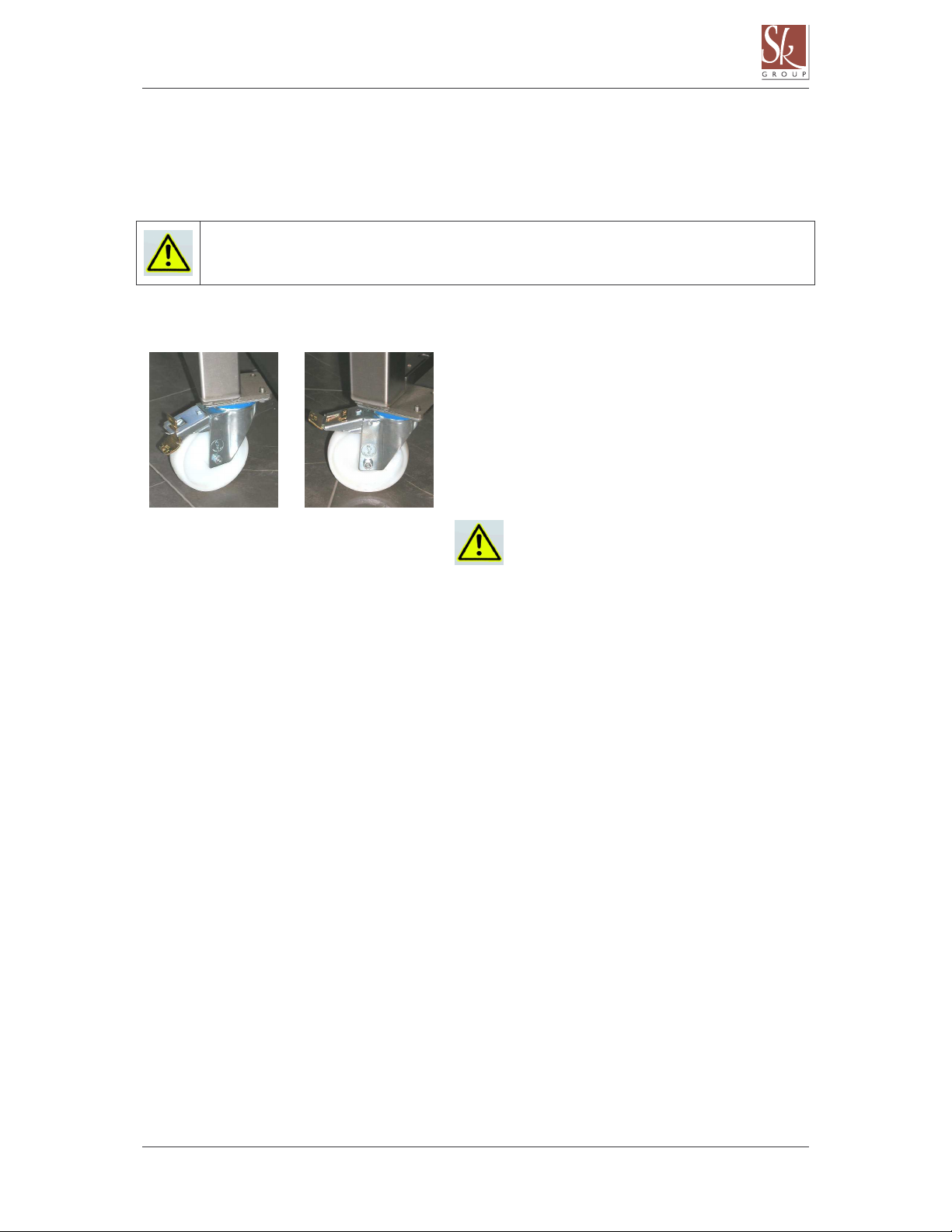
5.2 Mounting and storage of the press ................................................................................... 10
6 SWITCHING ON THE PRESS..................................................................................................... 11
6.1 Electrical connection.......................................................................................................... 11
6.2 Rotating direction of the drum .......................................................................................... 12
7 GENERAL DATA......................................................................................................................... 13
7.1 Technical data (dimensions and capacity) ....................................................................... 13
7.2 Press orientation ................................................................................................................ 14
7.3 Pneumatic press operation................................................................................................ 15
8 DESCRIPTION OF THE PNEUMATIC PRESS ........................................................................... 16
8.1 Components........................................................................................................................ 16
8.2 Built-in components........................................................................................................... 17
8.3 Materials.............................................................................................................................. 18
8.4 Sliding hatch....................................................................................................................... 18
8.4.1 Double sliding hatch (manual opening/closing).............................................................. 18
8.4.2 Double hatch with pneumatic drive (optional) ................................................................ 20
8.4.3 Hermetic hatch with manual opening/closing (optional for PST).................................... 21
8.4.4 Hermetic hatch with pneumatic drive (optional for PST) ................................................ 22
8.5 Press drum.......................................................................................................................... 23
8.6 Juice collection pan ........................................................................................................... 24
8.6.1 Small pan on guides (optional on PS_21 and PS_29) ................................................... 24
8.6.2 Large pan on wheels (optional on PS_21 and PS_29) .................................................. 25
8.6.3 Pan on guides (PS_42 and PS_55)............................................................................... 25
8.7 Control box ......................................................................................................................... 26
8.8 Optional equipment............................................................................................................ 26
8.8.1 Strainer on the collection pan outlet .............................................................................. 26
8.8.2 Level switch in the collection pan .................................................................................. 27
8.8.3 Equipment for macaration (only models PST) ............................................................... 28
9 OPERATING THE PRESS .......................................................................................................... 29
9.1 Before use........................................................................................................................... 29
9.2 Filling of the press.............................................................................................................. 29
9.2.1 Filling the press through the hatch................................................................................. 29
9.2.2 Filling the press through the central filling connector ..................................................... 30
9.3 Selecting the pressing program ........................................................................................ 32

NAV_PSL_ 2008/07_UK_v4
3
9.4 Discharging the press ........................................................................................................ 33
10 CLEANING OF THE PRESS.................................................................................................... 34
10.1 Cleaning of the drum interior............................................................................................. 34
10.2 Cleaning the drain channels (PST models) ...................................................................... 35
10.2.1 The draining channel dismounting procedure:............................................................... 35
10.2.2 Reassembly of the draining channels............................................................................ 36
10.3 Cleaning the drain channels without removing them (optional for PST models).......... 37
10.3.1 Channel cleaning hose (length: 3 m). ............................................................................ 37
10.4 Cleaning of the external parts of the press ...................................................................... 37
11 MAINTENANCE....................................................................................................................... 38
11.1 Removing humidity from the space between the drum and the membrane .................. 38
11.2 Checking of the drum rotation chain ................................................................................ 38
11.3 Membrane ........................................................................................................................... 39
11.4 Maintenance of the compressor........................................................................................ 40
11.5 Maintenace of the relief valve............................................................................................ 40
11.6 After the end of the vintage season .................................................................................. 40
11.7 Care and maintenence of stainless steel eqipment ......................................................... 41
11.8 Spare parts.......................................................................................................................... 43
12 CORRECTING ERRORS......................................................................................................... 43
Attachments:
- AV Automatics (Description and operating instructions)
- Electric scheme
- Instructions for use and maintenance of the compressor (provided by the compressor
manufacturer)
- Declaration of conformity
- Warranty declaration

NAV_PSL_ 2008/07_UK_v4
4
1 INTRODUCTION
We thank you for your trust, which you demonstrated by purchasing our pneumatic press.
In order for it to be used successfully and for a long period we ask you to follow the instructions and
warnings for a safe and proper use.
The instructions are intended for the operator and they should always be kept at hand. They describe
correct and safe use of the pneumatic presses series L model PSP_ and model PST_
21/29/42/55. As they cover different press types, they may describe functions and features not fitted in
your particular press.
Read the instructions carefully before:
- Unloading and installing the press
- Connecting the press to electricity
- Start of use
- Maintenance work
In the case of any doubt and/or need for additional information, please contact the
manufacturer or his representative.
IDENTIFICATION STICKER
On one leg of the press there is an identification sticker with
basic information on the press characteristics (serial number,
drum capacity, type of the press, technical data, year of
production …).
In case you need any additional information, spare parts or
service, always provide the data from the identification
sticker.
2 PURPOSE OF PNEUMATIC PRESS
Pneumatic presses are only designed for pressing grapes and lees. Use the press only for the
purposes intended and approved by the manufacturer.
In the case you intend to apply the press for any other purpose, consult the manufacturer prior to such
application. We cannot be held liable for any problems, damages, deformations, risks … that may
arise due to the application of the press for any purposes not explicitly approved by the manufacturer.
3 GUARANTEE
See the guarantee declaration.
The press manufacturer, Škrlj d.o.o., does not accept any liability for damages caused by
failure to observe instructions in this manual. Furthermore, we reject any liability for
damages caused by improper application of the machine and its accessories.
In the case of use for purposes not intended, failure to observe the instructions in this
manual or any tampering with the machine by non-authorised persons, the manufacturer's
guarantee becomes void.

NAV_PSL_ 2008/07_UK_v4
5
4 HEALTH AND SAFETY
4.1 Meaning of the symbols
In the instructions following symbols are used to warn the user against danger or special attention:
Symbol Designation Meaning
DANGER Danger because of the electric current!
DANGER Danger because of the moving parts of the machine!
WARNING General instruction, recommendation, forbiddance…!
IMPORTANT INFORMATION Information that demands special attention!
4.2 GENERAL SAFETY PRECAUTIONS
Due to its moving parts and to the pressure in the drum, the pneumatic press may be a threat to its
environment. Therefore, strictly observe safety precautions when operating the press. Unqualified and
unauthorized person is not allowed to use the press.
In a case of any unauthorised tampering with the machine, the manufacturer's guarantee becomes
void; furthermore, any unprofessional repairs may result in danger for the machine operator.
Disconnect the press from the mains power ALWAYS:
when it is not in use;
before any intervention in the machine
during the cleaning, control and maintenance procedure
in case of a damaged electrical cable
before opening the electric panel;
in case of any danger
In case of any danger stop the press by pressing the emergency STOP button or
with the safety cord.
Before any intervention in the machine make sure that:
the press is disconnected from network
the main switch of the press is in position OFF
The drum is not pressurised.
Opening of the hatch during the press operation is explicitly forbidden.
The hatch may only be opened for the filling the drum, for the discharging, for cleaning
purposes and for maintenance works in the press drum.
Before opening the hatch manually, disconnect the press and turn the main switch OFF.
Before entering the drum, secure the door against unintentional closing.
Do not reach in the space between the drum and the press frame. Danger of
squeezing!
This space is secured with a safety cord. The tension and position of the safety cord must
be checked before every use of the press.

NAV_PSL_ 2008/07_UK_v4
6
Once a year, the screws that connect the membrane to the drum frame must be tightened.
Before that, disconnect the press from the mains supply. The hatch should be open and
protected against inadvertent closing.
When filling with the pump, be careful not to exceed the limit pressure value in the drum.
You must stop the pump as soon as you hear the acoustic signal, in order to reduce the
pressure. Disregarding this instruction can lead to serious damage of the drum.
When filling the press, the recommended filling capacity should be observed (see chapter
9.2 Filling of the press).
The press drum is subject to the requirements laid down in the pressure equipment
directive (Official gazette of Slovenia, 15/2002; directive ES 97/23/EC). After setting up the
press, the producer has performed acceptance examination with the initial pressure test.
The user has to consider all the directives, that are in force in the country where the press
is operating. The user must also make sure that all the periodical tests according to this
directive are done.
4.3 SAFETY DEVICES
The press is equipped with safety devices which ensure safe work and undisturbed operation of the
press.
4.3.1 Emergency STOP button
When you push the emergency STOP button (the red button on the control
panel), the press immediately stops its operation.
Never use the emergency STOP to interrupt the grapepress normal running.
emergency
STOP button

NAV_PSL_ 2008/07_UK_v4
7
4.3.2 Safety cord
The space between the drum and the press frame is protected by a red safety cord. Any significant
vibration or pulling on the cord triggers a micro switch, which in turn immediately stops the press.
Always check the safety cord tension and position prior to operating the press. If the safety cord is not
installed or its tension is incorrect, the press will not function.
The safety cord runs along the internal edge of
the press frame. It is connected to the S4 micro
switch. The cord tension is proper when the end
of the black indicator is approximately in the
middle of the green strip, and the blue button
pulled out to show the green strip beneath it.
The cord tension is set by means of the screw at
the cord end. Any pulling on the cord triggers
automatic immediate stopping of the press.
press is displayed.
The blue button drops.
The press switches to a standstill.
Prior to resuming the press operation, determine
and remedy the trouble that caused the press to
stop.
To resume the press operation, lift the blue button
on the micro switch so as to show the green strip
underneath it.
Start the press by means of the green button on
the command panel and resume the cancelled
pressing programme.
mikroswitch S4
blue button -
dropped
green strip
black indicator
blue button -
lifted
green strip visible

NAV_PSL_ 2008/07_UK_v4
8
4.3.3 Protection against overpressure in the drum
Following safety systems are used:
1 Maximum pressure that can be achieved with the compressor is limited to 1.5 bar
(by some executions maximum pressure is 1.8 bar).
2
In a case the pressure is exceeded (e.g. due to a valve
fault), the vacuum pump valve and the safety valve
automatically open at 2.0 bar, to release air from the drum
and to decrease the pressure to the allowed level.
3
Presses with axial filling can also be equipped with a
sound alarm. The alarm is triggered if the pressure is
exceeded or the press is overfilled.
Make sure that you don't exceed the max. pressure
allowed douring the filling of the press.
In case the sound signal is activated, stop the filling pump
immediately.
4.3.4 Overload relays
The press has two overload relays (F1 and F2),
which are located in electric cabinet.
Use the supplied key to open and close the electric
box (upon delivery it is fixed on the cable below the
box).
The overload relay is activated in case of overloading, overheating or any
other trouble with the electromotor or compressor.
The overload relay F1 protects the drum rotation electromotor.
the overload relay F2 protects the compressor electromotor
By pressing the black button, the overload relay is reset.
ATTENTION:
Before resetting the overload relay, make sure that the problem that
caused the activation of the relay has been corrected/fixed.
Overload relays
safety valve
Sound
alarm

NAV_PSL_ 2008/07_UK_v4
9
5 PRESS TRANSPORT AND SETTING UP
5.1 Transport of the press
Transportation, unloading and lifting may only be done by skilled personnel.
The manufacturer shall not be kept liable for any personal injuries or material damages resulting
from disregarding safety regulations applicable to the transportation, unloading, lifting…
During lifting and manipulating the press, no person shall move or stay below the hoisted
load or within the operating range of the crane.
To hoist and transport the press, always apply the openings/hoisting eyes provided on the press for
this purpose.
The PSP/PST_21 and 29 size presses are fitted with four
hoisting openings in the hatch brackets (one opening on each
bracket). Attach the hoisting strap or lined steel rope hooks in
these openings.
The larger models are fitted with special lifting lugs located on
both ends of the drum.
Attach the hoisting strap or lined steel rope hooks in these
openings.
When you place the press or before
activating the press obligatory dismount
both lifting lugs.
Unscrew both screws fixing the lug to the
drum and remove the lug.
Store them in a safe place, as you may
need them later to transport the press again.
To unload and transport the press, apply appropriate lifting equipment (forklift, lift) and hoisting straps
or lined steel ropes. Make sure the strap/rope load bearing capacity is adequate for the press weight.
Designation
PSP 21
PST 21
PSP 29
PST 29
PSP 42
PST 42
PSP 55
PST 55
M (mass)
kg
810 1120 1800 2200
The strap/rope length shall be such as to carry the press in horizontal position during lifting. The
distance between the drum and the hook of the lift must be at least 1.5 m. Otherwise you must use
apropriate bracket to prevent the hatch brackets bending.
Attach the strap/rope hooks into the hoisting openings on the press. Hang both slings of the hoisting
straps/ropes on the lifting device hook and carefully lift the press. Make sure the load is balanced and
then lower the press, slowly and avoiding unnecessary oscillations, onto the intended position.
hoisting opening in t
he hatch
bracket

NAV_PSL_ 2008/07_UK_v4
10
5.2 Mounting and storage of the press
Pneumatic press is delivered wrapped in foil. The foil must be removed immediately after delivery.
Otherwise, effects of weather factors (exposure to strong sun radiation etc.) may hinder complete and
neat removal of the foil.
Place the press into a dry and vented space on a level floor. Protect it from dust and
direct sunlight. Excessive temperature can harm the controller and cause controller
malfunction.
Wheels:
PS_21 and PS_29 series presses have factory
installed wheels (two steerable wheels with a brake and
two fixed wheels).
For PS_42 and PS_55 series presses, these wheels
are optional.
By using the wheels, move the press to the foreseen
position.
Two of the wheels are fitted with a break pedal.
Wheel - brake activated
Wheel - brake released
The wheels of the press are exclusively
intended for moving an the press on a level
ground, never on a street paving or uneven
ground.

NAV_PSL_ 2008/07_UK_v4
11
6 SWITCHING ON THE PRESS
6.1 Electrical connection
The electrical connection of the press must be carried out by skilled personnel
(electrician)!
Electrical connections (including earth lead and protection) should be performed in
accordance with applicable standards.
Electrical diagrams are attached to the manual!
Connect the press to a three phase 400 V 50/60 Hz mains supply. The connecting terminals are
located in electrical box.
The connection has to be protected with adequate fuses:
pneumatic pressis PS_21/29 3 x 16 A fuse
pneumatic pressis PS_42 3 x 25 A fuse
pneumatic pressis PS_55 3 x 32 A fuse
Power cable requirements
pneumatic pressis PS_21/29 5 cored with a cross section of 2.5 mm
2
pneumatic pressis PS_42 5 cored with a cross section of 4.0 mm
2
pneumatic pressis PS_55 5 cored with a cross section of 6,0 mm
2
OPTION:
mains supply voltage other than 400V 50Hz
Connecting the cable and the electrical box:
Prior to the first startup, a qualified technician (electrician) shall connect the supply cable to the electric
cabinet. Observe the following procedure:
Step 1:
The electrical box is mounted beneath the
press front cover.
Lift the front cover of the press and make
sure that the cilinders sustain the cover in
the upper position.
Step 2:
Open the electric cabinet.
To open the box, use the supplied key.
On delivery, the key is attached underneat
the electric box.

NAV_PSL_ 2008/07_UK_v4
12
The identification tag is
positioned on the support
behind the box
Step 3:
Check the mains supply voltage indicated on
the identification sticker (on the leg of the
press) and on the yellow sticker under the
connecting terminals.
Step 4:
Insert the cable into the sleeve on the electric
cabinet right side and connect the supply
cable leads to the corresponding terminals.
This should be done by a skilled expert
(electrician)!
Step 5:
Close the electric cabinet and lock it with the
provided key. Keep the key on a safe place.
Close the cover of the press.
6.2 Rotating direction of the drum
Upon activating the press, check the rotating direction of the drum. Check the rotation in service mode by
using drum rotation switches.
The drum has to rotate in the direction indicated by the arrow on the button (from the front side
position) (see chapter 7.2 Press orientation).
rotating in clockwise direction (right)
rotating of the drum in anticlockwise direction (left)
In case of the opposite direction of the rotation, immediately change the phase leads of the supply cable.
Connection shall be done by a qualified technician (electrician).
Operating in the opposite drum rotation direction is not allowable and causes a breakdown of the
compressor.
sleeve
connecting terminals
Sticker with mains supply voltage

NAV_PSL_ 2008/07_UK_v4
13
7 GENERAL DATA
7.1 Technical data (dimensions and capacity)
Pneumatic presses, L series
PSP
open drum, semi-membrane, half of the drum perforated
Drum design
PST
enclosed drum, semi-membrane, draining channel
Designation
PSP 21
PST 21
PSP 29
PST 29
PSP 42
PST 42
PSP 55
PST 55
Drum volume
2,100 l
2,900 l
4,200 l
5,500 l
L
mm
3155 3975 4380 4930
Lcp
mm
3585 4405 4810 5360
D
mm
1600 1600 1800 1800
H
mm
1890 1890 2050 2120
S
mm
500 500 X
X
Scp
mm
1215 1215 1310 1310
A x B (hatch)
mm
470 x 900
470 x 900
490 x 900
490 x 900
M (mass)
kg
810 1120 1800 2200
V (collection
pan)
L
600 820 500 500
P (power)
kw
5,4 / 3,1 9,6 / 4,2 11 / 5,6 14,1 / 7,7
integral
grapes
kg
1100 -1700 1500 - 2300 2100 - 3200 2600 - 4000
fresh less
kg
3300 - 5300 4500 - 7300 6500 - 11000 8500 - 14000
capacity
ferment.
lees
kg
4800 - 7300 6700 - 10000 9700 - 15000 11000 - 19000
PSP/PST_ 21, 29

NAV_PSL_ 2008/07_UK_v4
14
Back side of the pre
ss
is the side with the the central
filling connector
PSP/PST_ 42, 55
7.2 Press orientation
When checking drum rotation, note that it is always regarded from the front.
The drum must rotate in the same direction as the arrow on the key.
Front side of the press
is the side where the drive
module of the maschine is
situated.

NAV_PSL_ 2008/07_UK_v4
15
7.3 Pneumatic press operation
Pneumatic press is a technical-oenological process tool designed for controlled pressing of grapes. It
allows the wine-maker to actively intervene in the processes in the course of pressing, to continually
adjust and govern the processes. Soft pressing of grapes or lees by means of a membrane and
compressed air prevents mechanical damaging of grapes (less damage to the hard parts of grapes)
and in turn minimises the leaching of undesired ingredients.
Pneumatic press operation
1 - filling 2 - pressing 3 - crumbling 4 - emptying
1. Press filling: The drum is filled with grapes or lees through opened hatch or by means of a central
filling connector. Even during the filling stage, must starts to drain into the collection trough under its
own weight. The axial filling system, which is available for every model, allows the filling of the dregs
at the same time as the drum rotates that improves the efficiency of the press.
2. Pressing: The drum, with hatches closed, faces down. The pressing takes place by means of
compressed air via the impermeable membrane. Must drains through perforated drum walls or drain
channels into the collection pan.
3. Crumbling: Air is evacuated, the membrane is stuck to the internal walls. The drum continues to
rotate.
4. Emptying: The hatches are open, the drum continues to rotate. During rotation, skins drop from the
press drum. Large hatches allow fast emptying.
The pressing pressure is achieved with the compressor, which is built in the press. The loosening of
the lees is performed by the rotation of the drum that is achived through electromotor over a chain
conveyor. Before each filling or rotation of the drum, the membrane is sucked up on the drum wall with
the vacuum pump. In this position the membrane is protected against eventual damage and it allowes
good shakes of the lees in the drum.
The pressing and rotation is repeated. The quality of the must depends mostly on these two processes
because it’s very important how (how much pressure) and how much time we press or loosen the
grapes or grapeskins. Therefore it’s important to set the pressing parameters regarding the sort,
maturity and desired outcome…

NAV_PSL_ 2008/07_UK_v4
16
8 DESCRIPTION OF THE PNEUMATIC PRESS
8.1 Components
Key press components. The equipment can differ for various press types and sizes.
Press drum
The front
cover with the
drive module
Juice collection
pan
Red safety cord
Double sliding
hatch
AVk controller
Central filling
connection

NAV_PSL_ 2008/07_UK_v4
17
8.2 Built-in components
Under the front cover is the drive module of the press.
When you open the front cover of the press, MAKE SURE that the hydraulic struts fix the
cover in the upper position.
Pneumatic presses PS_21, 29 and 42:
Pneumatic press PS_55:
An electric motor with reduction gear drives the drum via a chain transmission. Prior to each filling of
the drum / rotation of the drum, suction fix the membrane to the drum walls by means of the vacuum
pump.
The safety valve automatically opens in a case the drum pressure exceeds the allowable limit (2.0 bar).
The pressing pressure is achieved with the compressor, which is built in the press. As standard, the
pneumatic presses L are fitted with lamella compressor. The type and performance of the compressor
depends on press size.
safety valve
electromotor
vacuum pump
reduction gear
safety valve
electromotor
vacuum pump
reduction gear
Service
command
box
Comperssor

NAV_PSL_ 2008/07_UK_v4
18
Upon activating the press, check the rotating direction of
the drum. Operation with the improper rotation direction
is not allowable and could damage the compressor (for
detailed instructions, see chapter 6.2 Drum rotation
direction).
The presses that have hermetic hatches or any other form of pneumatic drive (hatch, pan etc.) have an
auxiliary compressor built in.
For detailed description and instructions for use and maintenance, see the instructions
provided by the compressor manufacturer.
8.3 Materials
All metal parts of the press that come in contact with the must are made from stainless steel EN
1.4301. This allows for high standards of hygiene and easy cleaning.
8.4 Sliding hatch
The presses have sliding hatches (double sliding hatches, dobule sliding hatches with pneumatic
drive, hermetic hatches, hermetic hatches with pneumatic drive). The dimensions and number of the
hatch depend on the press type.
A large hatch allows fast and easy filling and emptying of the press.
8.4.1 Double sliding hatch (manual opening/closing)
Hatch dimensions
pneumatic press PS_21 480 x 900 mm, double
pneumatic press PS_29 480 x 900 mm, double
pneumatic press PS_42 495 x 900 mm, double
pneumatic press PS_55 495 x 900 mm, double
Sliding hatch

NAV_PSL_ 2008/07_UK_v4
19
Perforated double sliding hatch for perforated drum presses
(PSP)
Double sliding hatches for closed drum presses with drain
channels (PST)
Manual opening of the hatch:
Opening the hatch in the upper position requires some strength.
Therefore, use the opening lever, which is included with the press.
Rotate the drum so that the hatch
stops in a position that is suitable
for opening.
Insert the lever between the two
halves as shown in the picture.
With one hand, hold the safety
pin on the outside of the frame,
and with the other, push the lever
as indicated by the picture.
Repeat the procedure for the
other half.
Make sure that the safety pin is released while opening the hatch in
order to make it easier to slide the hatch.
When closing the hatch, reverse the procedure. If you cannot close the hatch, use the lever.
Safety pin

NAV_PSL_ 2008/07_UK_v4
20
8.4.2 Double hatch with pneumatic drive (optional)
The pneumatic drive is particularly useful for large presses, as it makes closing and opening the hatch
much easier.
The drive can be installed on one or both hatches, and is controlled in manual mode (M) with the
following two keys:
key to open the hatch
key to close the hatch
The position and movement of hatches is controlled by two
sensors (basic version) or by three sensors (adjustable opening –
optional) on the pneumatic cylinder.
Sensor S1 – hatch closed
Sensor S2 – hatch partially open
Sensor S3 – hatch open
In the basic version, the movement is controlled by two sensors.
Sensor S1 – hatch closed
Sensor S3 – hatch open
In the adjustable opening version (optional), the hatch is regulated by three sensors.
Sensor S1 – hatch closed
Sensor S2 – hatch partially closed (the position of this sensor can be regulated later on)
Sensor S3 – hatch open
For additional information regarding use and functioning of the pneumatic hatch drive,
see the second part of this manual (Automatics AV)
See chapters:
2.2.6 Operating the sliding hatch
2.3.7 Pneumatic hatch with adjustable opening (optional)
Before any intervention in the press drum (cleaning,
control and maintenance procedures) activate the safety
valve of the pneumatic drive to secure the hatch against
inadvertent closing.
S3
S2
S1
Pneumatic
cylinder
Sliding hatch
safety valve
This manual suits for next models
8
Table of contents
Other SK Power Tools manuals
Popular Power Tools manuals by other brands

Laguna Tools
Laguna Tools DAKE 5 instruction manual

DeWalt
DeWalt XR DCF900P2T-QW Original instructions

Atlas Copco
Atlas Copco ETD M 25 AVB Product instructions

EINHELL Bavaria
EINHELL Bavaria BAS 18 A operating instructions

Goldenman Petroleum Equipment
Goldenman Petroleum Equipment XQ140/30-SM operating instructions

Mitox
Mitox 28MT Operator's manual

U-Line
U-Line Shrinkfast 975 manual

Ingersoll-Rand
Ingersoll-Rand 107G Operation and maintenance manual

Sealey
Sealey STW101 instructions

Stomer Professional
Stomer Professional SAD-18x2LiD-XL user manual

Cornwell Tools
Cornwell Tools IR-C103 instructions

King Industrial
King Industrial KC-15VS instruction manual