SK M Series User manual

IMPORTANT !
Before using the press for the rst time, you should check the functioning of the press. The control procedure is
described in the accompanying short instructions: Pneumatic press function control – before the rst use.
IMPORTANT !
Inspect your shipment immediately. Check the machine and all parts received and inspect them for potential
damage that may have occurred during shipping. If shipping damage is found, note it on the packing list and report
the damage to the carrier or contact the sales representetive of the manufacturer SK Group Škrlj d.o.o.
The accompanying documentation of the press includes the takeover checklist, where the components that need
to be checked are listed. Please, ll out the takeover checklist completely and precisely. Check all the components of
the press, as well as all equipment and accessories of the press. If you note some discrepancies or imperfections, we
ask you to indicate them in the checklist, and if necessary, add some additional documentation (photos, reclamation
record).
www.sk-group.biz
2
Address:
Škrlj d.o.o.
Dunajska cesta 196 · SI-1000 Ljubljana · Slovenia
Production and administration:
Škrlj d.o.o.
Batuje 90 · SI-5262 Črniče · Slovenia
tel.: 00386 5 364 35 00
fax: 00386 5 364 35 25
www.sk-group.biz
Document code: NAVU_PSM_2013-05(EN)
This instructions are property of the company ŠKRLJ d.o.o. The company reserves the right to make technical and other changes on the products and the
accompanying instructions without prior notice.
Please read and understand this manual prior to installing, operating or maintaining the machine.
ΑΦΟΙ ΓΑΒΡΙΗΛΙΔΗ Α.Ε.Β.Ε.
Σταδίου 101, Τ.Κ. 59100 Βέροια
Τηλ.23310 20262 Fax 23310 20263
http://www.agroenos.com

Pneumatic presses series M
3
TABLE OF CONTENTS
1 INTRODUCTION.............................................................................................................................................................................................5
2 INTENDED USE OF PNEUMATIC PRESS...................................................................................................................................................5
3 GUARANTEE....................................................................................................................................................................................................5
4 Health and safety .........................................................................................................................................................................................5
4.1 Meaning of the symbols............................................................................................................................................................................. 5
4.2 General safety precautions.......................................................................................................................................................................6
4.3 Safety devices................................................................................................................................................................................................7
4.3.1 Emergency STOP button.............................................................................................................................................................7
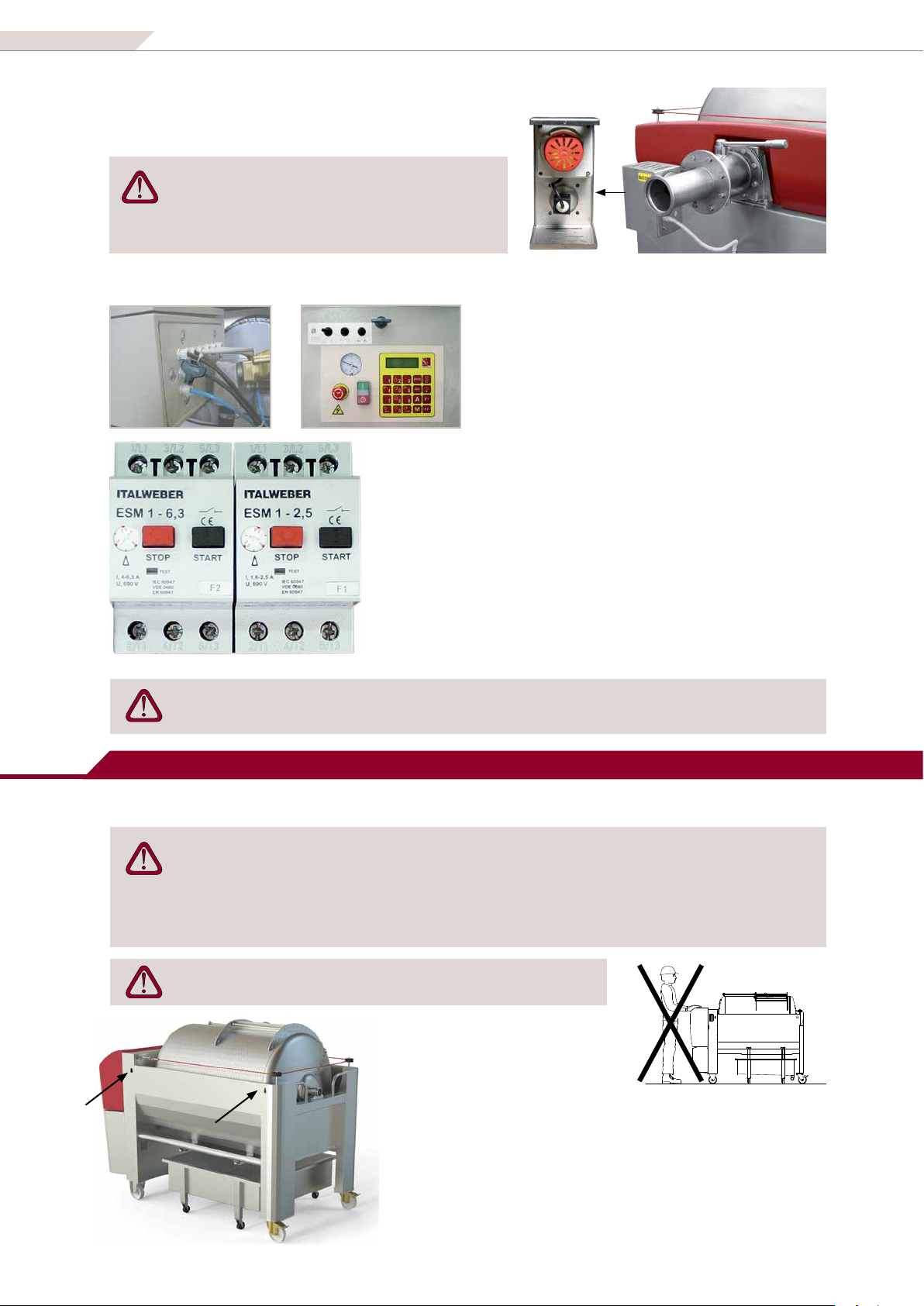
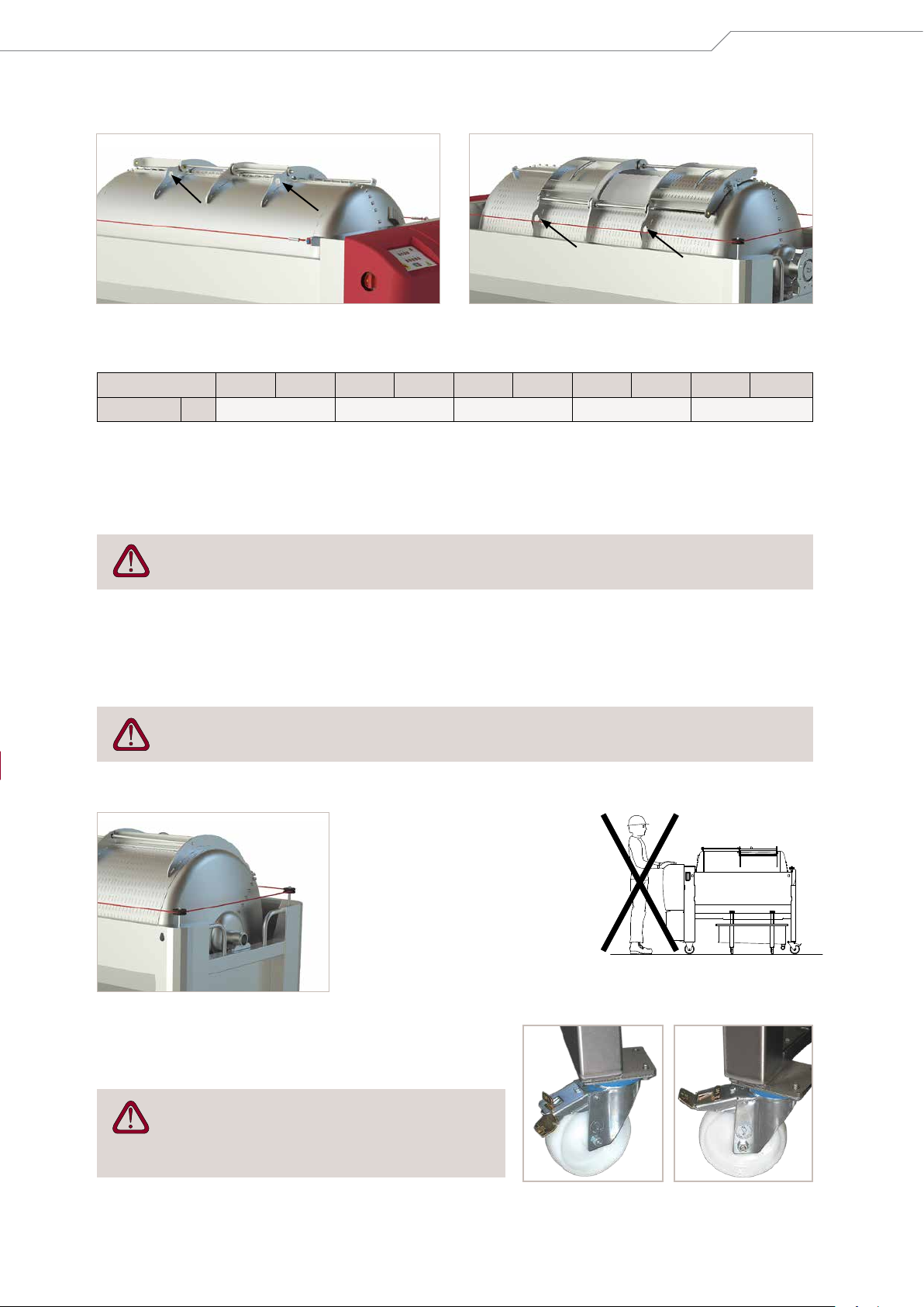
4.3.2 Safety cord .......................................................................................................................................................................................7
4.3.3 Protection against overpressure in the drum....................................................................................................................... 7
4.3.4 Overload relays...............................................................................................................................................................................8
5 PRESS TRANSPORT AND SETTING UP.....................................................................................................................................................8
5.1 Transport of the press.................................................................................................................................................................................8
5.2 Mounting and storage of the press........................................................................................................................................................9
6 SWITCHING ON THE PRESS ..................................................................................................................................................................... 10
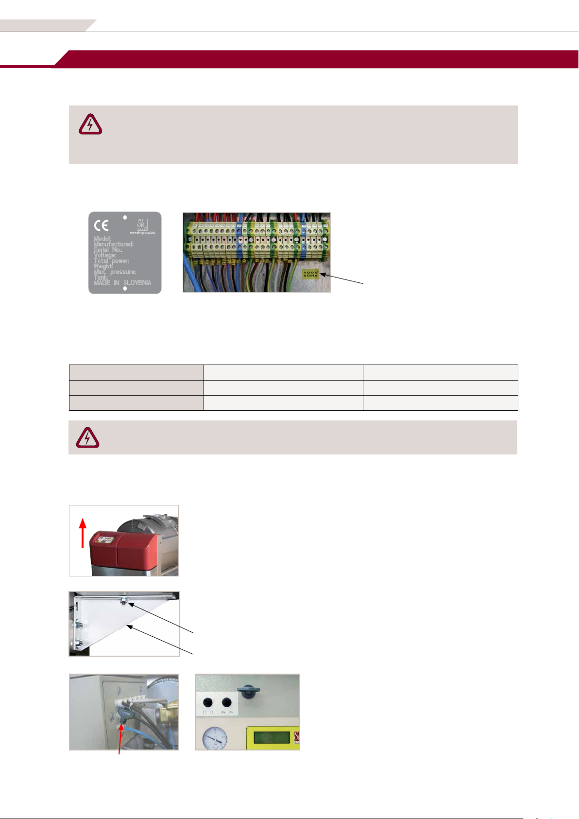
6.1 Electrical connection.................................................................................................................................................................................10
6.2 Rotating direction of the drum..............................................................................................................................................................11
6.3 Press orientation.........................................................................................................................................................................................11
7 GENERAL DATA............................................................................................................................................................................................12
7.1 Technical data (dimensions and capacity) .........................................................................................................................................12
7.2 Pneumatic press operation.....................................................................................................................................................................13
8 DESCRIPTION OF THE PNEUMATIC PRESS...........................................................................................................................................14
8.1 Components ................................................................................................................................................................................................14
8.2 Built-in components..................................................................................................................................................................................14
8.3 Materials........................................................................................................................................................................................................15
8.4 Sliding hatch ................................................................................................................................................................................................15
8.5 Press drum....................................................................................................................................................................................................16
8.6 Juice collection pan...................................................................................................................................................................................16
8.7 Control box...................................................................................................................................................................................................17
8.8 Optional equipment..................................................................................................................................................................................18
8.8.1 Strainer on the collection pan outlet ....................................................................................................................................18
8.8.2 Level switch in the collection pan..........................................................................................................................................18
8.8.3 Equipment for macaration (only models PST)....................................................................................................................18
8.8.4 Cooling jacket (as an option in PST models) .......................................................................................................................20
9 OPERATING THE PRESS ............................................................................................................................................................................ 22
9.1 Before use .....................................................................................................................................................................................................22
9.2 Filling of the press......................................................................................................................................................................................22
9.2.1 Filling the press through the hatch........................................................................................................................................22
9.2.2 Filling the press through the central filling connector....................................................................................................22
9.3 Selecting the pressing program............................................................................................................................................................24
9.4 Discharging the press ...............................................................................................................................................................................24
10 CLEANING OF THE PNEUMATIC PRESSES........................................................................................................................................... 25
10.1 Cleaning of the drum interior.................................................................................................................................................................25
10.1.1 Presses with no cleaning opening (PS_5, PS_8) ................................................................................................................25
10.1.2 Presses with a cleaning opening (PS_10, _12, _16)...........................................................................................................26

www.sk-group.biz
4
10.2 Cleaning the drain channels (PST models).........................................................................................................................................26
10.2.1 Removing the drain channels..................................................................................................................................................26
10.2.2 Reassembly of the draining channels ...................................................................................................................................27
10.2.3 Cleaning the drain channels without removing them (optional for PST models)..................................................27
10.3 Cleaning of the external parts of the press........................................................................................................................................28
11 MAINTENANCE ........................................................................................................................................................................................... 28
11.1 Removing humidity from the space between the drum and the membrane........................................................................28
11.2 Checking of the drum rotation chain...................................................................................................................................................28
11.3 Membrane ....................................................................................................................................................................................................29
11.4 Maintenance of the compressor............................................................................................................................................................29
11.5 Maintenace of the safety valve ..............................................................................................................................................................30
11.6 After the end of the vintage season.....................................................................................................................................................30
11.7 Care and maintenence of stainless steel eqipment........................................................................................................................30
11.8 Spare parts....................................................................................................................................................................................................31
12 CORRECTING ERRORS............................................................................................................................................................................... 32
Attachments:
fAE or AV Automatics (Description and operating instructions)
fElectric scheme
fInstructions for use and maintenance of the compressor (provided by the compressor manufacturer)
fDeclaration of conformity
fWarranty declaration

Pneumatic presses series M
5
1 INTRODUCTION
We thank you for your trust, which you demonstrated by purchasing our pneumatic press. In order for it to be used
successfully and for a long period we ask you to follow the instructions and warnings for a safe and proper use.
The instructions are intended for the operator and they should always be kept at hand. They describe correct and safe use of
the pneumatic presses series M model PSP_ and PST_ 5/8/10/12/16. As they cover dierent press types, they may describe
functions and features not tted in your particular press.
Read the instructions carefully before:
funloading and installing the press,
fconnecting the press to electricity,
fstart of use,
fmaintenance work.
In the case of any doubt and/or need for additional information, please contact the manufacturer or his
representative.
Identication plate
On one leg of the press there is an identication plate with basic information on the press
characteristics (serial number, drum capacity, type of the press, technical data, year of
production… ).
In case you need any additional information, spare parts or service, always provide the data
from the identication plate.
2 INTENDED USE OF PNEUMATIC PRESS
Pneumatic presses are only designed for pressing grapes and lees. Use the press only for the purposes intended and
approved by the manufacturer.
In the case you intend to apply the press for any other purpose, consult the manufacturer prior to such application.
The manufacturer cannot be held liable for any problems, damages, deformations and risks that may arise due to the
application of the press for any purposes not explicitly approved by the manufacturer.
3 GUARANTEE
See the guarantee declaration.
The press manufacturer, Škrlj d.o.o., does not accept any liability for damages caused by failure to observe instructions
in this manual. Furthermore, the manufacturer rejects any liability for damages caused by improper application of
the machine and its accessories.
In the case of use for purposes not intended, failure to observe the instructions in this manual or any tampering with
the machine by non-authorised persons, the manufacturer's guarantee becomes void.
4 HEALTH AND SAFETY
4.1 Meaning of the symbols
In the instructions following symbols are used to warn the user against danger or special attention:
DANGER Danger because of the electric current!
WARNING General instruction, recommendation, forbiddance…!

www.sk-group.biz
6
4.2 General safety precautions
Due to its moving parts and to the pressure in the drum, the pneumatic press may be a threat to its environment.
Therefore, strictly observe safety precautions when operating the press. Unqualied and unauthorized person is not
allowed to use the press.
In a case of any unauthorised tampering with the machine, the manufacturer’s guarantee becomes void; furthermore, any
unprofessional repairs may result in danger for the machine operator.
If the pneumatic press is placed in such a way as to prevent a safe access to all its working positions,
additional aids and tools should be used, in order to guarantee a safe access to these working positions.
For a safe access, ladders, staircases and platforms with anti-slip surface and guardrails should be used.
Platform and staircases are manufactured in conformance with the following standards:
fDIN EN ISO 14122-1:2002; Safety of machinery - Permanent means of access to machinery - Part 1: Choice
of a fixed means of access between two levels
fDIN EN ISO 14122-2:2002; Safety of machinery - Permanent means of access to machinery - Part 2: Working
platforms and walkways
fDIN EN ISO 14122-3:2002; Safety of machinery - Permanent means of access to machinery - Part 3:
Staircases, stepladders and guard rails
Disconnect the press from the mains power ALWAYS:
fwhen it is not in use,
fbefore any intervention in the machine,
fduring the cleaning, control and maintenance procedure,
fin case of a damaged electrical cable,
fbefore opening the electric panel,
fin case of any danger.
In case of any danger stop the press by pressing the emergency STOP button or with the safety cord.
Before any intervention in the machine make sure that:
fthe press is disconnected from network,
fthe main switch of the press is in position OFF,
fthe drum is not pressurised.
Opening of the hatch during the press operation is explicitly forbidden.
The hatch may only be opened for the filling the drum, for the discharging, for cleaning
purposes and for maintenance works in the press drum.
Before opening the hatch manually, disconnect the press and turn the main switch OFF.
Before entering the drum, secure the door against unintentional closing.
Do not reach in the space between the drum and the press frame. Danger of squeezing!
This space is secured with a safety cord. The tension and position of the safety cord must be checked
before every use of the press.
Once a year, the screws that connect the membrane to the drum frame must be tightened. Before that,
disconnect the press from the mains supply. The hatch should be open and protected against inadvertent
closing.
When filling with the pump, be careful not to exceed the limit pressure value in the drum. You must
stop the pump as soon as you hear the acoustic signal, in order to reduce the pressure. Disregarding this
instruction can lead to serious damage of the drum.
When filling the press, the recommended filling capacity should be observed (see chapter 9.2 Filling of the press).
The press drum is subject to the requirements laid down in the pressure equipment directive PED 97/23/EC.
After setting up the press, the producer has performed acceptance examination with the initial pressure
test. The user has to consider all the directives, that are in force in the country where the press is operating.
The user must also make sure that all the periodical tests according to this directive are done.

green strip
black indicator
mikroswitch S4
blue button - dropped
blue button - lifted
green strip visible
Pneumatic presses series M
7
4.3 Safety devices
The press is equipped with safety devices which ensure safe work and undisturbed operation of the press.
4.3.1 Emergency STOP button
When you push the emergency STOP button the
press immediately stops its operation.
Never use the emergency STOP to
interrupt the grapepress normal
running.
4.3.2 Safety cord
The space between the drum and the press frame is protected by a red safety cord. Any signicant vibration or pulling on
the cord triggers a micro switch, which in turn immediately stops the press.
Always check the safety cord tension and position prior to operating the press. If the safety cord is not installed or its
tension is incorrect, the press will not function.
The safety cord runs along the internal edge of the press frame.
It is connected to the S4 micro switch. The cord tension is proper
when the end of the black indicator is approximately in the
middle of the green strip, and the blue button pulled out to show
the green strip beneath it.
The cord tension is set by means of the screw at the cord end.
Any pulling on the cord triggers automatic immediate stopping
of the press.
The blue button drops.
The press switches to a standstill.
Prior to resuming the press operation, determine and remedy the
trouble that caused the press to stop.
To resume the press operation, lift the blue button on the micro
switch so as to show the green strip underneath it.
Start the press by means of the green button on the command
panel and resume the cancelled pressing programme.
4.3.3 Protection against overpressure in the drum
For protection against overpressure in the drum following safety systems are
used:
1 Maximum pressure that can be achieved with the compressor is limited
to 1.5 bar (by some press models maximum pressure is 1.8 bar).
2 In a case the pressure is exceeded (e.g. due to a valve fault), the
vacuum pump valve and the safety valve automatically open at 2.0
bar, to release air from the drum and to decrease the pressure to the
allowed level.
safety valve

F1
F2
www.sk-group.biz
8
3 Presses with axial filling can also be equipped with a sound
alarm. The alarm is triggered if the pressure is exceeded or
the press is overfilled.
Make sure not to exceed the max. pressure allowed
douring the filling of the press.
In case the sound signal is activated, stop the lling
pump immediately.
4.3.4 Overload relays
The press has two overload relays (F1 and F2), which are
located in electric cabinet.
To open and close the electric cabinet, apply the
provided key. The key is xed to the cable on the cabinet
side at delivery.
The overload relay is activated in case of overloading, overheating or any
other trouble with the electromotor or compressor.
The overload relay F1 protects the drum rotation electromotor.
The overload relay F2 protects the compressor electromotor
By pressing the black button, the overload relay is reset.
ATTENTION!
Before resetting the overload relay, make sure that the problem that
caused the activation of the relay has been corrected/xed.
The presses with a built-in single-phase compressor have a circuit breaker incorporated in the compressor
itself. It is reset by pushing on the switch button.
5 PRESS TRANSPORT AND SETTING UP
5.1 Transport of the press
Transportation, unloading and lifting may only be done by skilled personnel.
The manufacturer shall not be kept liable for any personal injuries or material damages resulting from
disregarding safety regulations applicable to the transportation, unloading, lifting…
During lifting and manipulating the press, no person shall move or stay below the hoisted load or within
the operating range of the crane.
Do not push on the plastic covers on the front side of the press.
To hoist and transport the press,
always apply the openings/hoisting
eyes provided on the press for this
purpose.
The PS_5 and _8 size presses are tted with four openings on the press
frame (two openings on each side). Attach the hoisting strap or lined steel
rope hooks in these openings.

Wheel - brake activated Wheel - brake released
Pneumatic presses series M
9
The PS_10,_12 and _16 size presses have hoisting openings in the hatch brackets. Attach the hoisting strap or lined steel
rope hooks in the openings.
To unload and transport the press, apply appropriate lifting equipment (forklift, lift) and hoisting straps or lined steel
ropes. Make sure the strap/rope load bearing capacity is adequate for the press weight.
Press type PSP 5 PST 5 PSP 8 PST 8 PSP 10 PST 10 PSP 12 PST 12 PSP 16 PST 16
M (mass) kg 300 350 500 520 610
The strap/rope length shall be such as to carry the press in horizontal position during lifting.
Attach the strap/rope hooks into the hoisting openings on the press. Hang both slings of the hoisting straps/ropes on
the lifting device hook and carefully lift the press. Make sure the load is balanced and then lower the press, slowly and
avoiding unnecessary oscillations, onto the intended position.
Smaller presses can be unloaded and transported with a forklift of adequate capacity and fork length.
Attach the forks along the press length, to reach from the command cabinet to the frame back side.
5.2 Mounting and storage of the press
Pneumatic press is delivered wrapped in foil. The foil must be removed immediately after delivery. Otherwise, eects of
weather factors (exposure to strong sun radiation etc.) may hinder complete and neat removal of the foil.
Place the press into a dry and vented space on a level floor. Protect it from dust and direct sunlight.
Excessive temperature can harm the controller and cause controller malfunction.
Handles for moving the press
To move the press, use the handles.
Do not push on the plastic covers on
the front and back side of the press.
Wheels
With the help of the wheels the press can be moved to the desired
location. Two of the wheels are tted with a break pedal.
The wheels of the press are exclusively intended for
moving an empty press on a level ground, never on a
street paving or uneven ground.

electric cabinet bracket
electric cabinet fixing screw
key
www.sk-group.biz
10
6 SWITCHING ON THE PRESS
6.1 Electrical connection
The electrical connection of the press must be carried out by skilled personnel (electrician)!
Electrical connections (including earth lead and protection) should be performed in accordance with
applicable standards.
Electrical diagrams are attached to the manual!
Connect the press to the required source of electrical power (single phase, three phase). Check the mains supply voltage
indicated on the identication plate (on the leg of the press) and on the yellow sticker under the connecting terminals.
Check the mains supply voltage indicated
on the identication plate and on the yellow
sticker under the connecting terminals.
The connection has to be protected with adequate fuses:
Connection voltage 400V 50Hz, three phase 230V 50Hz, single phase (option)
Fuses 3 x 16 A fuse 1 x 16 A fuse
Power cable requirements 5 leads with a cross-section of 2.5 mm
2
3 leads with a cross-section of 2.5 mm
2
If the mains supply voltage is other than 230/400V 50Hz follow the instructions provided by the
manufacturer.
Connecting the cable and the electrical box
Prior to the rst startup, a qualied technician (electrician) shall connect the supply cable to the electric cabinet. Observe
the following procedure:
Remove the plastic press cover; for this purpose, hold it with hands on both sides and
pull upwards.
Loosen the screws on the brackets beneath the electric cabinet to allow the cabinet to be
pulled out.
Open the electric cabinet.
To open and close the electric cabinet, apply the
provided key. At delivery the key is xed to the cable
on the cabinet side.
The identification plate is
positioned on the support
behind the box
The connecting terminals are located
in electrical box.
Sticker with mains
supply voltage

Pneumatic presses series M
11
Insert the cable into the sleeve on the electric
cabinet right side and connect the supply cable
leads to the corresponding terminals.
Connection shall be done by a qualied
technician (electrician).
Close the electric cabinet and lock it with the provided key. Keep the key on a safe place. Slide the cabinet back into the
housing. Tighten the screws on the electric cabinet brackets. Attach the press plastic cover.
6.2 Rotating direction of the drum
Upon connecting the press, check the rotating direction of the drum using drum rotation buttons. When checking drum
rotation, note that it is always regarded from the front side of the press. The drum has to rotate in the direction indicated
by the arrow on the button.
AE automatics: rotating in anti-clockwise direction
AV automatics: rotating in clockwise direction
rotating of the drum in anticlockwise direction
In case of the opposite direction of the rotation, immediately change the phase leads of the supply cable.
Connection shall be done by a qualified technician (electrician).
Operating in the opposite drum rotation direction is not allowable and causes a breakdown of the
compressor.
In the case of single-phase supply presses, the drum rotation direction is already preset in the factory and
does not need checking.
6.3 Press orientation
sleeve
Back side is the side with the
axial filling connector
Front side is the side where
the drive module of the press is
located
When checking drum rotation, note that it is always regarded from the front side. The drum must rotate in
the same direction as the arrow on the key.

www.sk-group.biz
12
7 GENERAL DATA
7.1 Technical data (dimensions and capacity)
Drum
design
PSP open drum, semi-membrane, half of the drum perforated
PST enclosed drum, semi-membrane, draining channel
Designation PSP 5 PST 5 PSP 8 PST 8 PSP 10 PST 10 PSP 12 PST 12 PSP 16 PST 16
Drum volume 500 l 800 l 1000 l 1200 l 1600 l
Lmm 1820 2320 2530 2575 3070
Lcp mm 2960 3005 3500
Dmm 1000 1000 1220 1220 1220
Hmm 1420 1420 1540 1600 1610
Smm 450 400 390 390 390
Scp mm 1035 1035 1045
A x B mm 345 x 425 345 x 425 345 x 650 345 x 650 345 x 900
M (mass) kg 300 350 500 520 610
V (collection pan) l150 150 250 250 250
P (power) kW 3,1/1,55 3,9/1,95 3,9/1,95 3,9/1,95 4,6/2,3
capacity
integral
grapes kg 250-400 400-650 500-800 600-950 800-1200
fresh less kg 700-1000 1100-1500 1400-1800 1650-2250 2400-4000
ferment.
lees kg 1000-1600 1500-2500 1800-3100 2250-3750 3500-5500
PSP/PST_5,8
PSP/PST_10,12,16

Pneumatic presses series M
13
7. 2 Pneumatic press operation
Pneumatic press is a technical-oenological process tool designed for controlled pressing of grapes. It allows the wine-
maker to actively intervene in the processes in the course of pressing, to continually adjust and govern the processes. Soft
pressing of grapes or lees by means of a membrane and compressed air prevents mechanical damaging of grapes (less
damage to the hard parts of grapes) and in turn minimises the leaching of undesired ingredients.
Pneumatic press operation:
1 - filling 2 - pressing 3 - crumbling 4 - emptying
1. Press lling: The drum is lled with grapes or lees through opened hatch or by means of a central lling connector.
Even during the lling stage, must starts to drain into the collection trough under its own weight. The axial lling
system, which is available for every model, allows the lling of the dregs at the same time as the drum rotates that
improves the eciency of the press.
2. Pressing: The drum, with hatches closed, faces down. The pressing takes place by means of compressed air via the
impermeable membrane. Must drains through perforated drum walls or drain channels into the collection pan.
3. Crumbling: Air is evacuated, the membrane is stuck to the internal walls. The drum continues to rotate.
4. Emptying: The hatches are open, the drum continues to rotate. During rotation, skins drop from the press drum.
Large hatches allow fast emptying.
The pressing pressure is achieved with the compressor, which is built in the press. The loosening of the lees is
performed by the rotation of the drum that is achived through electromotor over a chain conveyor. Before each
lling or rotation of the drum, the membrane is sucked up on the drum wall with the vacuum pump. In this position
the membrane is protected against eventual damage and it allowes good shakes of the lees in the drum.
The pressing and rotation is repeated. The quality of the must depends mostly on this operation because it’s very
important how (how much pressure) and how much time we press or loosen the grapes or grapeskins. Therefore it’s
important to set the pressing parameters regarding the sort, maturity and desired outcome.

www.sk-group.biz
14
8.2 Built-in components
PS_5 and PS_8 presses (piston compressor): PS_10, PS_12 and PS_16 presses (piston compressor):
8 DESCRIPTION OF THE PNEUMATIC PRESS
8.1 Components
sliding hatch
safety cord
juice collection pan
press drum
control board
the front cover
with the drive module
vacuum pump
safety valve
reduction
gear
electromotor
vacuum
pump
safety valve
reduction
gear
electromotor
PS_16 press (lammelar compressor):
vacuum pump
integrated lamella
compressor
reduction gear
electromotor

Pneumatic presses series M
15
The pressing pressure is achieved with the compressor, which is built in the press. As standard, the pneumatic presses M
are tted with piston compressors. As an option, an integrated lamella compressor is available.
An electric motor with reduction gear drives the drum via a chain transmission.
Prior to each lling of the drum / rotation of the drum, suction x the membrane to the drum walls by means of the
vacuum pump.
The safety valve automatically opens in a case the drum pressure exceeds the allowable limit (2.0 bar).
If the press is equipped with a lamellar compressor (optional), it does not have a safety valve. The lamellar compressor has
its own protection, adjusted with a knob. The limits are factory preset.
In the case of the presses fitted with lamella compressors, check the drum rotation direction after each
start. Operation with the improper rotation direction is not allowable and could damage the compressor
(for detailed instructions, see chapter 6.2 Drum rotation direction).
For detailed description and instructions for use and maintenance, see the instructions provided by the
compressor manufacturer.
8.3 Materials
All metal parts of the press that come in contact with the must are made from stainless steel EN 1.4301. This allows easy
cleaning of the metal surfaces.
8.4 Sliding hatch
The press is equipped with a sliding hatch. A large hatch allows fast and easy lling and
emptying of the press. The dimensions and number of the hatch depend on the press type.
Hatch dimensions:
Pneumatic press PS_5 and _8 345 x 425 mm, single
Pneumatic press PS_10 and _12 345 x 650 mm, double
Pneumatic press PS_16 345 x 900 mm, double
The sprung hatch closing mechanism should be released before opening the hatch.
After closing the hatch, secure them with the closing mechanism to prevent them from
opening inadvertendly.
Regulation knob
integral piston compressor for presses
PSP/PST_5
integral piston compressor for presses
PSP/PST_8/10/12/16
OPTION: integrated lamella compressor
Sprung hatch closing
mechanism

www.sk-group.biz
16
8.5 Press drum
The press drum is constructed according to pressure vessel guidelines (PED 97/23/EC).
The horizontal shape of the drum, combining large length and small diameter, allows faster outow of juice, which results
in less sediment in the must. On the inside, the drum is lined with an impermeable membrane shaped to cover half of
the drum surface. The built in compressor maintains a set pressure in the drum during the pressing process, to impose
pressure on the grapes and squeeze must.
Drum design PSP (open drum)
One half of the drum surface is perforated, and the other half is lined with an
impermeable membrane.
Must leaves the drum through its perforated half into the collection pan.
Likewise, the PSP drum hatch is made of special perforated steel. During the pressing
process, the hatch also serves to lead must into the collection pan.
Drum design PST (enclosed drum)
On the inside, one half of the press drum is lined with pressing membrane, while
the other half is tted with perforated drain channels.
Must ows through drain channel openings into the collection pan.
8.6 Juice collection pan
Juice pan volume:
PS 5 and 8 presses 150 litre
PS 10, 12 and 16 presses 250 litre
The pan is attached to the press frame. To facilitate movement, it has
wheels.
Accessories for the juice pan (optional):
flevel switch in the collection pan, only available with AV automatics
(see chapter 8.8.2 Level switch in the collection pan)
fstrainer on the collection pan outlet (see chapter 8.8.1 Strainer on the
collection pan outlet).

Pneumatic presses series M
17
8.7 Control box
The automatics (controller) provide for proper ow of the pressing process in accordance with the set parameters. The
press can be tted with AE automatics (factory preset programmes) or AV automatics (factory preset programmes that
can be set and adjusted during the pressing process).
AE automatics
The AE automatics allows two operating modes:
fmanual press operation
fautomatic operation
In the manual mode, the user starts and ends a particular operation by
depressing a button (drum rotation, compressor, vacuum pump on/o).
In the automatic mode, the user can choose between ve standard
pressing programmes. The incorporated programmes are based on
years of experience and are adjusted to dierent types of grapes. The
programmes are factory preset.
For further instructions on AE automatics, see included instructions.
AV automatics
The AV automatics allows two operation modes:
fmanual operation (button M)
fautomatic operation (button A)
In the manual mode, the user starts and ends a particular operation by
depressing a button.
In the automatic mode, the user can choose between ten pressing
programmes, which are adjusted, observing professional experience, to
dierent grape types (programmes are identied by number keys on the
keyboard):
0, 1, 2, 3, 4, 5 - standard pressing programmes
6, 7, 8 - sequential programmes
9- a programme specically adjusted to the pressing of ice grapes
The user can set the pressing parameters and adjust them during the
pressing process as required.
For further instructions on AV automatics, see included instructions.
AV automatics on a cable with connector
The AV automatics control panel is connected to the press via a cable and
connector. This allows mounting in dierent locations on the press itself or
separate installation. Operation is the same as with AV module.
For transport, the control panel is xed, with two screws, on the press
frame under the front lifting cover.
Before use, control panel can be xed with same two screws on the left or
right side of the press frame on mounted connections.
For further instructions on AV automatics, see included instructions.

1 A
0
1A
0
=–
www.sk-group.biz
18
8.8.2 Level switch in the collection pan
The level switch is designed to control the operation of the pump which transfers must from the collection pan to the
container during the pressing.
8.8 Optional equipment
8.8.1 Strainer on the collection pan outlet
Install the strainer on the drain opening from the inside. The strainer traps pips
and other particles from the must; thereby, only pure liquid passes from the
collection pan into the container.
The collection pan is tted with two oats on a
special metal bracket.
fWhen must in the pan reaches its
maximum allowable level (the top oat in
its top position), the must transfer pump is
switched on.
fWhen must in the pan reaches its
maximum allowable level (the top oat in
its top position), the must transfer pump is
switched on.
Automatic operation:
To activate automatic mode put the switch in position [A]. In automatic mode the level switch is during pressing all the
time in function in order to prevent the juice collection pan from overlling. The electronics controles the level of the
must in the collection pan irrespectiv of the program going on in the press.
In case the must level does not decrease in a certain time period (due to the clogging of the drain opening, pump fault
etc.), the pressing is automatically suspended. The drum is rotated so that the perforated half of the drum or the half with
drain channels is facing up in order to prevent the must from leaking. The press switches to a standstill.
After the error is removed, the program can continue on from where it was interrupted.
Manual operation:
In the manual mode in position [1] the must pump is on and in position [0] the must pump is o. Choosing the position [1]
allows the user to empty the collection pan completely.
8.8.3 Equipment for macaration (only models PST)
The hatch opening cover combined with the plugging of drain
channel outlets, allow lees maceration and its agitation by means of
the press drum rotation.
Prior to start pressing, MAKE SURE TO REMOVE the hatch opening cover and plugs from the drain channel
openings.Pressing with hatch opening cover and plugs installed is not allowed.
top level pin
top float
bottom level pin
bottom float
switch
pump
connector
must pump on
must pump off
automatic mode

seal
Pneumatic presses series M
19
To perform maceration, follow these instructions:
fBefore lling the press, rotate the drum to bring the hatch to its top position.
fInsert drain channel plugs. With the channels closed, you can ll the press with lees up to the hatch, since the liquid
can not drain during lling.
fFill the drum. During lling, the hatch must be open (see also 10.2 Filling the press)
fWhen the press is full, install the hatch cover according to the procedure described below.
fOnce the cover is installed, execute the maceration program (only available with AV module).
Installation of the cover:
When installing the hatch cover pay attention that the
side with engraved number is on the same side as the
identication plate of the drum.
The engraved number on the hatch cover must match
with the serial number of the press drum.
Open the hatch completely. Make sure that the hatch is
secured against sudden closing.
Loosen the xing screws so you can attach the cover on
the frame. Lift the cover carefully using the handles. By
pulling on the handle, the mounting prole is released,
allowing you to latch the cover onto the frame.
Attach the cover on one side rst. Make sure that the seal
ts on the inside along the whole length.
Once the cover is in place on one side, repeat the procedure on the other side. By
pulling the handle towards the outer edge of the cover, release the bottom mounting
bracket to make sure the cover snaps into place. Be careful not to bend the seal while
installing the cover.
Straigthen the cover. While moving it, hold both handles so that the mounting
bracket below is released and does not damage the seal.
Once the cover is in place, tighten all screws to achieve perfect sealing.
Warning!
All xing screws come with a gasket and a
washer. Do not use excessive force in order not
to damage the gaskets.
After maceration is over, remove the cover by
repeating the procedure in reverse order.
1 – mounting bracket
2 – fixing screw
3 – door handle
4 – door cover
The dimensions of the hatch depend on the press type.

www.sk-group.biz
20
Maceration (only available with the AV module)
key for maceration program
(only for Presses with drum design PST – closed drum with drain channels)
After closing the hatch and plugging the drain channels, turn on the drum lling pump and activate the maceration
program. Press the key on the control panel and enter the desired parameters.
For deteiled informations see the additional Manual for AV Automatics.
fChapter 2.3 Manual operation mode
fChapter 2.3.5 Maceration program (entering and changing parameters)
8.8.4 Cooling jacket (as an option in PST models)
Pneumatic presses with closed drum can optionally have a cooling jacket and accompanying connectors to the cooling
medium (water, glycol). The press drum is surrounded by a cooling layer, which contains a cooling medium. This system
enables the winemaker the cooling of pomace in the drum during the maceration and pressing.
Cooling jacket – technical data:
fworking pressure: 3 bar
ftesting pressure: 6 bar
fcooling medium: water, glycol
finlet and outlet connectors: 3/4’’ quick couplings
fcooling surface (the table contains approximate values)
Pneumatic press Drum volume (l) Cooling jacket (m
2
)
PST 5 500 1,40
PST 8 800 2,25
PST 10 1000 2,30
PST 12 1200 2,75
PST 16 1600 3,50
Connection to the cooling system
Disobeyance of the following instructions and warnings can result in the loss of guarantee of the producer
and can cause a system malfunction.
Connectors
The cooling jacket is connected to the cooling medium through
two connectors on the external drum surface. Each of the two
connectors can be used as an inlet or outlet connector.
The cooling jacket can be connected to the cooling medium
only when the drum does not rotate.
Before the drum starts moving, the supply of the cooling medium should always be disconnected, except
in cases when the press is equipped by a rolling connector system.
This manual suits for next models
10
Table of contents
Other SK Power Tools manuals
Popular Power Tools manuals by other brands

Parker
Parker KarryKrimp 1 operation instruction

HOSCH
HOSCH HD-PU-L Installation and operation manual

Central Machinery
Central Machinery 92804 Assembly and operating instructions

Josef Kihlberg
Josef Kihlberg JK24-690 manual

Rikon Power Tools
Rikon Power Tools 30-240 Operator's manual

Kobalt
Kobalt KJS 324B-03 manual

Powerfix Profi
Powerfix Profi 114396 Operation and safety notes

BGS technic
BGS technic 8231 instruction manual

Rothenberger
Rothenberger SV28 Instructions for use

Reliable Equipment
Reliable Equipment REL-LP-O Operator's guide

Carrier
Carrier 40VMV0012A Installation and maintenance instructions

Makita
Makita TW004G instruction manual