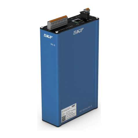
SKF Multilog On-Line System IMx-M User manual

User manual
Copyright 2017 by SKF Group
All rights reserved.
SKF Condition Monitoring Center –Luleå
Aurorum 30, 977 75 Luleå, Sweden
Telephone: +46 (0) 31 337 10 00, Fax: +46 (0) 920 134 40
SKF Multilog On-Line
System IMx-M
User Manual Part No. 32179800-EN
Revision P
Protection FW 378
IMx-M Manager 2.1.31
WARNING! Read this manual before using this product. Failure to follow the instructions and safety
precautions in this manual can result in serious injury, damage to the product, or incorrect readings. Keep
this manual in a safe location for future reference.

® SKF is a registered trademark of the SKF Group.
All other trademarks are the property of their respective owners.
© SKF 2017
The contents of this publication are the copyright of the publisher and may not be reproduced (even
extracts) unless prior written permission is granted. Every care has been taken to ensure the accuracy of
the information contained in this publication but no liability can be accepted for any loss or damage whether
direct, indirect or consequential arising out of the use of the information contained herein. SKF reserves the
right to alter any part of this publication without prior notice.
Patents: US 4,768,380 • US 5,633,811 • US 5,679,900 • US 5,845,230 • US 5,852,351 •
US 5,854,553 • US 5,854,994 • US 5,870,699 • US 5,907,491 • US 5,992,237 • US 6,006,164 •
US 6,124,692 • US 6,138,078 • US 6,199,422 • US 6,202,491 • US 6,275,781 • US 6,301,514 •
US 6,437,692 • US 6,489,884 • US 6,513,386 • US 6,633,822 • US 6,789,025 • US 6,792,360 •
US 7,103,511 • US 7,697,492 • WO/2003/048714
Product Registration
Please take a moment to register your product at www.skf.com/cm/register to receive exclusive benefits
offered only to our registered customers, including technical support, tracking your proof of ownership, and
staying informed about upgrades and special offers. (Please visit our website for more details on these
benefits.)
General Product Information
General information such as product user manuals and catalogs are published on the Condition Monitoring
Products site on SKF.com. General product information can also be downloaded from the self-service web
portal at SKF.com/cm/TSG.
Product Support Contact Information
Repair and Calibration Services –Submit a Return Authorization (RA) request to arrange for repair or
calibration of your product. You will receive an RA number and shipping instructions usually within 48
business hours.
Product Support Plans (PSP) - SKF offers annual renewal Product Support Plans (PSP) on many condition
monitoring products in an effort to extend the life of your product. Software and firmware updates are an
exclusive entitlement to PSP customers. Additional benefits include product repair, Annual Preventative
Maintenance (APM), and certified calibration - all of which are all carried out on a priority-basis. Enjoy
unlimited technical support and access to after-hours support for machine- and process-critical
applications.
Product Sales - For information on purchasing condition monitoring products, services and support on
products out of warranty, please contact your local SKF sales office or distributor.

Technical Support - SKF's Technical Support Group can be reached during normal business hours via
phone, e-mail, and live chat. Always check the self-service web portal before contacting your nearest
Technical Support Group (TSG) to see if the answer is already published. You may search the vast
knowledgebase within the self-service web portal for answers to commonly-asked questions (FAQ), how-to
articles, technical specs, installation and user manuals, best practices and more.
Open a support ticket online now using our support request tool.
Customers in Europe, Middle East, and Africa:
Phone: +46 31 337 6500
E-Mail: TSG-EMEA@skf.com
Chat: www.skf.com/cm/tsg
Customers in the Americas, Asia, and all other locations:
Phone: 1-858-496-3627 or toll-free (USA) 1-800-523-7514
E-Mail: TSG-Am[email protected]
Chat: www.skf.com/cm/tsg
SKF Knowledge Centre - Read about topics of interest or join in on the discussion with maintenance and
reliability specialists from around the world in the SKF Knowledge Centre.
120517dm-fp


SKF Multilog On-Line System IMx-M TOC - 1
User Manual
Table of Contents
Introduction 1-1
Important Messages .................................................................................................. 1-1
System Overview........................................................................................................ 1-5
IMx-M General Overview .......................................................................................... 1-6
IMx-M Rack and Components............................................................................ 1-6
IMx-M System Main Parts.................................................................................. 1-7
IMx-M's Unique Features ................................................................................... 1-7
Condition Monitoring Module (CMM) Buffer Storage Capacity .................... 1-8
Initiating an IMx-M............................................................................................... 1-8
IMx-M Mean Time to Failure (MTTF) ............................................................... 1-9
Protection 2-1
Safety Considerations................................................................................................ 2-1
Accuracy....................................................................................................................... 2-2
Facts to Consider Regarding Accuracy ............................................................. 2-2
Accuracy is Relative to API 670 Defined Full Scale........................................ 2-3
Measurement Types .................................................................................................. 2-4
Absolute Shaft Vibration ..................................................................................... 2-5
Casing Vibration.................................................................................................... 2-6
Complementary Differential Expansion............................................................ 2-7
Eccentricity ............................................................................................................ 2-8
Gap.......................................................................................................................... 2-8
Supported sensor-types......................................................................................... 2-9
Other....................................................................................................................... 2-9
Measurement with Voltage Output Sensor.......................................................... 2-9
Current (4-20 mA) or Voltage (0-10 V) ............................................................... 2-9
Precautions / Special Care ..................................................................................... 2-9
Configurable Engineering Units...........................................................................2-11
Piston Rod Drop .................................................................................................2-12
Piston Rod Drop Physical Properties ..................................................................2-12
Operating Modes...................................................................................................2-13
Piston Rod Drop Combined Measurement.........................................................2-17
Trigger System and Measuring Angles...............................................................2-17
Trigger Physical Interface ....................................................................................2-19
Using Digital Input as Measurement Trigger .....................................................2-20

TOC - 2 SKF Multilog On-Line System IMx-M
User Manual
Position ................................................................................................................2-20
Radial Shaft Vibration........................................................................................2-21
Speed ...................................................................................................................2-21
Temperature.......................................................................................................2-21
Alarms ........................................................................................................................2-22
Trip Multiply Factor............................................................................................2-22
Alarm Status Propagation ................................................................................2-23
Alarm Trigger Filtering......................................................................................2-24
Hysteresis...............................................................................................................2-24
Alarm Delayed Trigger and Release....................................................................2-25
First Out Indication.............................................................................................2-26
Relays .........................................................................................................................2-27
Relays on Relay Modules ..................................................................................2-28
Safety Consideration When Configuring Relays ...........................................2-31
Slot Status Relays on Protection Module ......................................................2-32
Behavior of Relay at Channel Startup............................................................2-34
Protection Part Operation.......................................................................................2-35
Startup.................................................................................................................2-35
Circuit Faults (cf) ................................................................................................2-36
PRM Circuit Faults.................................................................................................2-37
RLM Circuit Faults.................................................................................................2-42
CMM Circuit Faults ................................................................................................2-46
Bit Representation of Combined Conditions.......................................................2-47
Local Display and Local Display Selection Keypad.......................................2-49
Start Menu.............................................................................................................2-50
Bar Graph Display .................................................................................................2-51
Buffered Outputs Front Menu .............................................................................2-52
Channel Values......................................................................................................2-53
Channel Action.......................................................................................................2-54
Disarm..................................................................................................................2-58
Channel Disarm.....................................................................................................2-58
Slot Disarm ............................................................................................................2-59
Rack Disarm...........................................................................................................2-60
Release of Rack/Slot Disarm after Configuration...............................................2-60
Protection Configuration Update.....................................................................2-60
Protection Firmware Update............................................................................2-61
IMx-M Manager........................................................................................................2-62
Installation of IMx-M Manager ........................................................................2-62
Introduction to IMx-M Manager ......................................................................2-62
Project Creation and Configuration Flow.......................................................2-65
Launching the Application ................................................................................2-66
Creating a New Project .....................................................................................2-66
Editing an Existing Project................................................................................2-67
Entering Administration Mode.........................................................................2-68

SKF Multilog On-Line System IMx-M TOC - 3
User Manual
Navigating IMx-M Manager Main Menu ........................................................2-68
"File" Menu Selection............................................................................................2-68
"Show" Menu Selection ........................................................................................2-74
"Serial Communication" Menu Selection ............................................................2-74
Validating and Saving Protection Configurations .........................................2-81
Sending Protection Configuration to Protection Module ............................2-81
Disarming a Slot....................................................................................................2-81
Sending Protection Configuration to PRM .........................................................2-81
Checking for Circuit Faults ...................................................................................2-82
Establishing a Connection between Host PC and Protection Module..............2-83
Getting Protection Configuration from Protection Module.........................2-83
Export to Excel File ............................................................................................2-84
Import from Excel File .......................................................................................2-85
Generate Report File .........................................................................................2-85
Maintenance View..............................................................................................2-85
Status.....................................................................................................................2-87
Analog ....................................................................................................................2-88
Combined Meas.....................................................................................................2-88
Digital .....................................................................................................................2-89
Relays.....................................................................................................................2-90
Utilities ...................................................................................................................2-91
Acceptance Test ....................................................................................................2-91
Protection Module Configuration with IMx-M Manager....................................2-95
Building a Configuration Hierarchy.................................................................2-95
Adding a Plant Node.............................................................................................2-95
Adding an Area Node............................................................................................2-96
Adding Rack, Slot and Relay Nodes..................................................................... 2-96
Setting Slot Properties......................................................................................2-98
Assigning Protection Settings (PRM) ..................................................................2-99
Configuring Network Settings (CMM) ...............................................................2-101
Saving a Network Configuration........................................................................2-104
Updating Network Configuration.......................................................................2-105
Configuring a Slot............................................................................................ 2-105
Configuring Analog Channels........................................................................ 2-105
Initiating an Analog Channel ..............................................................................2-107
Configuring an Analog Channel .........................................................................2-110
Configuring Combined Measurements........................................................ 2-119
Identification........................................................................................................2-120
Sensor..................................................................................................................2-121
Acquisition ...........................................................................................................2-122
Alarm Levels........................................................................................................2-123
Configuring Digital Channels......................................................................... 2-126
General Settings for Speed Type.......................................................................2-128
Alarm Levels for Speed Type.............................................................................2-129
Configuring 4-20 mA Outputs...................................................................... 2-130
Configuring a Relay Module .......................................................................... 2-131
Available Relay Types .........................................................................................2-133
General Settings for Relays................................................................................2-134

TOC - 4 SKF Multilog On-Line System IMx-M
User Manual
Channel Setup for Relays .................................................................................. 2-136
Basic Analog and Digital Channel Setup .......................................................... 2-140
Advanced Analog and Digital Channel Setup................................................... 2-141
Configuration Examples ................................................................................. 2-143
Absolute Shaft Vibration.................................................................................... 2-143
Complementary Differential Expansion............................................................ 2-151
Piston Rod Drop (PRD) ...................................................................................... 2-160
GAP...................................................................................................................... 2-171
Other.................................................................................................................... 2-173
Modbus.................................................................................................................... 2-180
Modbus (L1, L2) for PRM .............................................................................. 2-180
Exported (Read) Modbus Registers .................................................................. 2-180
Imported (Write Single) Modbus Registers...................................................... 2-195
Modbus (L3) for CMM..................................................................................... 2-196
Condition Monitoring 3-1
Condition Monitoring Part Operation...................................................................... 3-1
Condition Monitoring Data Analysis ........................................................................ 3-1
IMx-M Time................................................................................................................. 3-1
Automatic Time Synchronization ...................................................................... 3-1
Manual Set Time.................................................................................................. 3-2
Hardware 4-1
Installation ................................................................................................................... 4-1
Scenario................................................................................................................. 4-1
Rack / Cabinet....................................................................................................... 4-2
Cooling ................................................................................................................... 4-3
General Electrical Interface ................................................................................ 4-6
Sensor Cables ..........................................................................................................4-6
Supply Cable ............................................................................................................4-6
Signal Grounding.....................................................................................................4-7
Signal Isolation ........................................................................................................4-8
Mains Power............................................................................................................4-9
Power Supply.........................................................................................................4-11
Power Fuses ..........................................................................................................4-12
Inrush Current .......................................................................................................4-12
Sensor Power Output ...........................................................................................4-12
Condition Monitoring Part Electrical Interface..............................................4-13
Communication Cable ...........................................................................................4-13
Data Communication ............................................................................................4-13
Ethernet Cable.......................................................................................................4-13
Hardware Configuration..........................................................................................4-13
General Configuration .......................................................................................4-14
Analog Inputs.........................................................................................................4-14
Digital Inputs..........................................................................................................4-19
Buffered Outputs...................................................................................................4-23
Protection Part Configuration..........................................................................4-24

SKF Multilog On-Line System IMx-M TOC - 5
User Manual
RS485 Modbus .....................................................................................................4-24
4-20 mA Output ...................................................................................................4-25
Protection Module Serial (USB) Interface...........................................................4-26
Condition Monitoring Part Configuration.......................................................4-27
Condition Monitoring Module Serial (USB) Interface.........................................4-27
LED Indicators...........................................................................................................4-29
Power Supply Unit (PSU)..................................................................................4-29
Relay Module (RLM)...........................................................................................4-30
Condition Monitoring Module (CMM) ..............................................................4-31
Protection Module (PRM)..................................................................................4-32
Protection Part Diagnostic Commands ................................................................4-36
Condition Monitoring Part Diagnostic Commands .............................................4-37
Network Related Condition Codes...................................................................4-37
Hardware Maintenance...........................................................................................4-38
Maintenance of Sensors ...................................................................................4-38
Ventilation Fan....................................................................................................4-38
Hot-swap.............................................................................................................4-38
Changing Modules..............................................................................................4-42
Changing Module Labels...................................................................................4-43
Event Log 5-1
Troubleshooting Guide 6-1
Problems and Symptoms ......................................................................................... 6-1
Component Check ...................................................................................................... 6-3
Firmware Recovery.................................................................................................... 6-8
Problem ................................................................................................................. 6-8
Resolution.............................................................................................................. 6-8
Technical Data 7-1
Environmental............................................................................................................. 7-1
Rack .............................................................................................................................. 7-1
Power Supply .............................................................................................................. 7-1
Power Consumption .................................................................................................. 7-2
Analog Inputs - Protection & CM............................................................................. 7-2
Digital Inputs - Protection & CM.............................................................................. 7-2
Outputs - Protection.................................................................................................. 7-2
Analog Measurement - Protection.......................................................................... 7-3
Digital Measurement –Protection .......................................................................... 7-3
Relay - Protection ...................................................................................................... 7-3
Signal Processing - Protection ................................................................................ 7-4
Interface - Protection ................................................................................................ 7-4
Analog Measurement - CM ...................................................................................... 7-4
Digital Measurement - CM....................................................................................... 7-5

TOC - 6 SKF Multilog On-Line System IMx-M
User Manual
Signal Processing - CM............................................................................................. 7-5
Interface - CM............................................................................................................. 7-5
Miscellaneous.............................................................................................................. 7-5
Quality Control ............................................................................................................ 7-6
Drawings and Connections ....................................................................................... 7-7
IMx-M Rack Drawing with Dimensions ............................................................ 7-7
Front Panel............................................................................................................ 7-8
Rear Panel............................................................................................................. 7-9
Power Supply Unit (PSU)..................................................................................7-10
Relay Module (RLM)...........................................................................................7-11
Condition Monitoring Module (CMM)..............................................................7-12
Protection Module (PRM)..................................................................................7-13
CMM + PRM Slot Connections.........................................................................7-14
Analog Inputs.........................................................................................................7-14
Digital Inputs..........................................................................................................7-15
RS485, Relay Outputs, Rack Disarm...................................................................7-15
Buffered Analog Channel Out ..............................................................................7-16
Buffered Digital Channel Out ...............................................................................7-16
4-20 mA Out .........................................................................................................7-17
Relay Module (RLM) Connections....................................................................7-18
DIP Switches on Protection Module ...............................................................7-21
DIP Switch and Jumper on Condition Monitoring Module..........................7-22
Part Number Information 8-1
Main Components ...................................................................................................... 8-1
Add-on modules................................................................................................... 8-2
Components .......................................................................................................... 8-2
Spare parts & accessories......................................................................................... 8-3
Wiring connector blocks...................................................................................... 8-3
Electrical Waste 9-1
Glossary 10-1
Limited Warranty A-1
Index i i-1

SKF Multilog On-Line System IMx-M 1 - 1
User Manual
1
Introduction
Important Messages
The following messages are important information that require special care in order to
have a safe and reliable IMx-M system.
Important messages, instructions and information in this manual must be
followed carefully. Otherwise, harm might occur to equipment and/or personnel.
IMx-M shall be used for speed alarming only. It shall not be used to protect/trip
machine on overspeed. IMx-M does not fulfill the requirements related to
overspeed protection.
All safety critical decisions must be driven by the data from the protection
module.
Always use relay outputs for the safety/danger triggering.
Use @ptitude Observer only for monitoring purposes.
Use 4-20 mA outputs only for monitoring purposes.
Use Modbus data only for monitoring purposes.
Note: Be sure to always monitor the circuit fault status (circuit fault relay).
In order to ensure a safe system, installation, configuration and maintenance
of the system must be done by trained personnel only.
An IMx-M rack/cabinet contains circuit boards that are static sensitive.
Therefore, appropriate precautions must be used to prevent electrostatic discharge
(ESD) when handling circuit boards, refer Rack/Cabinet.
Each module must be placed correctly in the designated slot. The designated
slot of the each module is shown in Front Panel in Drawings and Connections
section.

Introduction
Important Messages
1 - 2 SKF Multilog On-Line System IMx-M
User Manual
A condition monitoring module (CMM) and a protection module (PRM) must be
installed as a pair in order to ensure the internal power redundancy.
Due to the physical reason, when mounting a pair of CMM and PRM, must
always mount the PRM before the CMM in order to avoid any damages to the PRM.
However, when dismounting a pair of CMM and PRM, it must be the other way
around. Always dismount the CMM before the PRM. Otherwise, the PRM can be
seriously damaged.
In general, all signal cables must be routed as far away as possible from the
high voltage cables.
It is always recommended to use high quality shielded cables and care must be
taken to ensure that the shield is properly connected to eliminate interference and
noise.
Grounding procedure must be handled with special care to prevent ground
loops:
Be sure to read "Signal Grounding" and "Signal Isolation" chapters thoroughly
and understand them.
SKF USB isolator cables must always be used when connecting to IMx-M USB
ports.
Equipment connected to buffered outputs must be isolated from the protective
earth.
Instrument ground (IGND) should be connected and joined to protective
earth/ground at one point only.
In general, it is recommended to connect shield to the ground in only one side
of the sensor/signal cable to avoid potential ground loops.
An IMx-M rack must be connected to protective earth since surge suppressors
are connected between network terminals and protective earth.
Make sure that protective earth and instrument ground (IGND) are properly
connected before connecting any of the input or output terminals of IMx-M rack.

Introduction
Important Messages
SKF Multilog On-Line System IMx-M 1 - 3
User Manual
All wires and cables connected to input and output terminals shall have a
flammability rating VW-1, FT-1 or fulfill the requirements according to IEC 60332-
1-2 or IEC 60332-2-2.
Because of the redundant power supply, both supply circuits (power connectors
AC1 and AC2) must be disconnected before maintenance. Refer to Mains Power
section.
Caution to a possible hazard due to mains power double pole/neutral fusing.
An IMx-M rack must be situated in a cabinet with a metal bottom or plastic
bottom with flammability classification of at least V-1. The cabinet must fulfill at
least IP 20.
Each IMx-M rack must be equipped with a forced ventilation which has a feed
of at least 3 x 95 m3/h (unrestricted airflow) in order to keep the rack environment
temperature as low as possible, ideally below 30 °C / 86 °F.
IMx-M is designed to operate in an environment of maximum operating
temperature of 65 °C / 149 °F. However, operating IMx-M at this temperature
shall be avoided as it will drastically shorten the lifetime of all components.
PRM with revision number 20 and above has an internal temperature
measurement device/sensor. The internal temperature is monitored and
registered via Event Log. If the rack is operated above 65 °C / 149 °F, the
warranty will be voided.
The recommended fan tray is of at least 3 x 12 cm fan and must be mounted
directly above or below each IMx-M rack (see Cooling section for the proper
installation guidelines).
The cooling fan must be UL or CSA approved and inspected regularly for
optimal performance.
The IMx-M rack is a class A equipment intended for use in an industrial
environment.
The usage of 4-20 mA outputs is only for monitoring purposes. Use relay
outputs for safety alert/danger triggering.

Introduction
Important Messages
1 - 4 SKF Multilog On-Line System IMx-M
User Manual
In order to release rack/slot disarm the following conditions must be met:
Rack disarm shall not be released until the rack is configured properly and is
running with a correct firmware. Be sure to read "Disarm" chapter and
"Protection Firmware Update" chapter thoroughly and understand them.
Slot disarm shall not be released until the protection module and the
associated relay module are configured properly and are running with a correct
firmware. Be sure to read "Disarm" chapter and "Protection Firmware Update"
chapter thoroughly and understand them.
Evaluate circuit faults with the diagnostic command "cf" before rack/slot
disarm is released. Be sure to read "Circuit Faults (cf)" chapter thoroughly and
understand it.
Evaluate channel alarms after a configuration update but before disarm is
released to avoid unwanted alert/danger alarms triggered upon arm of
channel/rack/slot.
Note: A premature release of rack/slot disarm may cause a missing or invalid
configuration, which would be indicated as a circuit fault.
In order to perform hot-swap, the following conditions must be met: (See
section Hot-swap for proper procedures)
The rack must be set in rack disarm mode before the hot-swap procedure
takes place. Be sure to read "Disarm" chapter thoroughly and understand it.
After the hot-swap but before the rack/slot disarm is released, user must
ensure that the rack/protection module and the associated relay module are
properly configured. Be sure to read "Protection Configuration Update" chapter
thoroughly and understand it. Evaluate circuit faults with the diagnostic
command "cf" as described in chapter "Circuit Faults (cf)".
After the hot-swap but before the rack/slot disarm is released, user must
ensure that the rack/protection module and the associated relay module are
running with a correct firmware. Be sure to read "Protection Firmware Update"
chapter thoroughly and understand it. It is always recommended to check with
the diagnostic command "intd0" that the correct firmware is running on all
protection MCUs. Evaluate circuit faults with the diagnostic command "cf" as
described in chapter "Circuit Faults (cf)".
In case of hot-swap of a power supply unit, be sure to read "Power Supply"
chapter thoroughly and understand it.
DIP switch settings must be handled with a special care to prevent any damage
to the IMx-M rack:
Do NOT change DIP switch settings while the IMx-M rack is powered-up, as
this may cause damage and void warranty.
Before powering up the IMx-M rack, make sure that DIP switch settings are
properly set to match the recommendations for the connected sensors.
Incorrect settings may cause permanent damage to the IMx-M rack.

Introduction
System Overview
SKF Multilog On-Line System IMx-M 1 - 5
User Manual
System Overview
The SKF Multilog On-line System IMx-M is one of the current generation of powerful,
cost effective solutions suitable for a variety of machinery monitoring applications.
Together with SKF @ptitude Monitoring Suite software, the SKF Multilog IMx-M can
provide a complete system for initiation of machinery shutdown, early fault detection
and diagnosis. In addition, the SKF Multilog IMx-M system can provide automated
advice for correcting existing or impending conditions that can affect machine reliability,
availability and performance.
Figure 1 - 1.
System Overview, IMx-M with @ptitude Observer.
The picture above illustrates how IMx-M racks are on one side connected to different
sensors and measuring points while on the other side linked together through various
interfaces like relay outputs, RS485 and Ethernet LAN for plant control and information
exchange. The plant networks are connected to various control and monitoring systems,
amongst them an @ptitude Monitoring Suite and Observer Monitor.

Introduction
IMx-M General Overview
1 - 6 SKF Multilog On-Line System IMx-M
User Manual
The @ptitude Observer Monitor in turn can be connected to e.g. a LAN network making
it possible for several of @ptitude Observer clients to link to this network.
It is also possible to connect different types of on-line units in the same network, for
example, IMx-M together with IMx-S and DMx.
IMx-M General Overview
Figure 1 - 2.
A Fully Equipped IMx-M Rack.
The above figure shows an example of a fully equipped IMx-M rack with (from left to
right) two redundant power supply units, three relay modules and four pairs of a
condition monitoring module and a protection module.
Each module may also be referred as a “slot”.
IMx-M Rack and Components
Designed to fit into a 19" rack enclosure, an IMx-M rack is equipped with the following
components:
Power supply unit (PSU or PSU slot)
–Two redundant power supply units
Relay module (RLM or RLM slot)
–Up to three relay modules
–Each relay module has 32 relays (28 SPDT and four DPDT), hence up to 96
relays in total with up to three RLM

Introduction
IMx-M General Overview
SKF Multilog On-Line System IMx-M 1 - 7
User Manual
–All relays are placed upon relay modules except for circuit fault and disarmed
relays which are placed upon protection module.
–All relays upon relay modules are user configurable.
Condition monitoring module and protection module pair ("CMM + PRM" or "CMM +
PRM slot")
–Up to four pairs of a condition monitoring module and a protection module
–Analog channels
oEach CMM + PRM slot has 16 analog signal inputs
oUp to 64 analog signal inputs in total when having four CMM + PRM slots
oThe dynamic signal inputs are configurable for a wide variety of sensors.
Signals, such as acceleration, velocity and displacement or other
parameters are easily adopted. Each input can also be configured for
standard accelerometers, 4–20 mA or ±23 V.
oSeveral measurement points may be attached to one channel and both AC
and DC measurements can be measured on the same channel
–Digital channels
oEach CMM + PRM slot has eight digital channels
oUp to 32 digital channels in total when having four CMM + PRM slots
oDigital channels are available for measuring speed, trigger or digital status;
for example, indicating when a measurement can take place
IMx-M System Main Parts
Machine protection part for the safety related functions which consists of
protection modules and relay modules.
Condition monitoring part for early fault detection (non-safety related functions)
which consists of condition monitoring modules.
Power supply units are a common part for both machine protection and condition
monitoring.
IMx-M's Unique Features
Individual conditions for alert and danger may be set for each measurement point.
Each channel has indicators for alert and danger. However, it is also possible to
manually bypass the alert and danger functionality.
The rack is offering remote reset of latching alert/danger conditions.
All channels are fully computed in parallel, both condition monitoring and machine
protection.
The built-in hardware auto-diagnosis system continuously checks all sensors,
cabling and electronics for any faults, signal interruption, short circuits or power
failure.

Introduction
IMx-M General Overview
1 - 8 SKF Multilog On-Line System IMx-M
User Manual
The design ensures that a single circuit failure cannot affect more than two
measurement channels and it is possible to detect and indicate the circuit failure.
The system makes it possible to have selected channels configured for redundancy.
All channels are designed to prevent any one channel from affecting any other
channel.
Condition Monitoring Module (CMM) Buffer Storage Capacity
Each condition monitoring module has 8 MB flash memory used for the following.
–2 MB for firmware, configuration files, etc.
–2 MB for trend value buffer
oAbout 13 000 vibration trend values can be buffered
oSpeed and process data use half the space of vibration
–4 MB for spectra and time signal buffer
oAbout 250 spectra using 1 600 lines with phase and time signal can be
buffered
oIf more lines are used, the number of spectra is reduced.
oIf less lines are used, the number of spectra is increased
–When the buffer gets full, the oldest data is thrown away.
Initiating an IMx-M
The machine protection configuration is done through the application tool called
IMx-M Manager and a (portable) computer using the USB interface located on
protection modules or via @ptitude Observer over an Ethernet connection.
The condition monitoring configuration is done through @ptitude Observer
software.
All initial network configuration parameters, such as IP address, IMx identification
number, etc. are done through the application tool called IMx-M Manager. The
parameters are stored first in a separate configuration file, then transferred to the
IMx-M memory.
The configuration is retained in the event of power losses, so that the IMx-M can
start automatically when power returns.

Introduction
IMx-M General Overview
SKF Multilog On-Line System IMx-M 1 - 9
User Manual
IMx-M Mean Time to Failure (MTTF)
IMx-M MTTF was calculated to 20,8 years, where the protection module has 25,2
years, the relay module has 139,6 years and the backplane has 772,3 years.
The calculation was done under the environmental conditions 40 °C / 104 °F and for
the following configuration of the IMx-M machinery protection system:
two analog input channels
four alarm relay outputs
two analog buffered outputs
one digital eddy current probe input
one digital buffered output
two front panel analog buffered outputs
one front panel buffered digital output
two RS485 outputs
Disarm input, disarm relay and circuit fault relay

Table of contents
Other SKF Control System manuals
Popular Control System manuals by other brands

IPAS
IPAS DaliControl e64 ProS Operating and mounting instructions

tbs electronics
tbs electronics H64 Installation instructions & user manual

Rinnai
Rinnai RS100 Operating and installation instructions

McCue
McCue BOL-WALKWAY installation instructions

Milltronics
Milltronics RH Series Instruction handbook

Evco
Evco EVJ LCD manual

GCHV
GCHV GCHV-E252W/ZR1 manual

Continental Refrigerator
Continental Refrigerator E-Access WI2427LF installation instructions

Schako
Schako EasyS-H01 user manual

SICE Tech
SICE Tech WHY PRO WHY-PH1 INSTRUCTION MANUAL AND WARNINGS

Rinnai
Rinnai Pure Control Installation & user manual

Len Gordon
Len Gordon Lennovator Owner's installation & operations manual