Contents
Safety . . . . . . . . . . . . . . . . . . . . . . . . . . .
Explanation of signal words
for safety . . . . . . . . . . . . . . . . . . . . . . . .
Description. . . . . . . . . . . . . . . . . . . . . . .
Specifications . . . . . . . . . . . . . . . . . . . .
Installation. . . . . . . . . . . . . . . . . . . . . . .
Operation . . . . . . . . . . . . . . . . . . . . . . . .
Disassembly and cleaning . . . . . . . . . .
Filter cleaning option . . . . . . . . . . . . . .
Filter cleaning option . . . . . . . . . . . . . .
Filter cleaning option . . . . . . . . . . . . . .
Bypass pin replacement. . . . . . . . . . . .
Removal . . . . . . . . . . . . . . . . . . . . . . . . .
Installation . . . . . . . . . . . . . . . . . . . . . . .
Filter assembly tips. . . . . . . . . . . . . . . .
Individual parts break down and
parts list. . . . . . . . . . . . . . . . . . . . . . . . .
Warranty . . . . . . . . . . . . . . . . . . . . . . . .
Safety
Read and carefully observe these operating
instructions before unpacking and operating
filter. Filter must be operated, maintained
and repaired exclusively by persons familiar
with operating instructions. Local safety
regulations regarding installation, operation
and maintenance must be followed.
Operate filter only after safety
instructions and this service manual are
fully understood.
Explanation of signal
words for safety
NOTE
Emphasizes useful hints and
recommendations as well as
information for efficient and trouble-
free operation.
DANGER
Indicates a dangerous situation that can
lead to death or severe injury if
precautionary measures are ignored.
Specifications
Model Model A
Collapse pressure psi (41,4 bar) psi (41,4 bar)
Screen size mm
Inlet 1/2 in NPTF 1/2 in NPTF
Outlet 1/2 in NPTF 1/2 in NPTF
Maximum working pressure 5 000 psi (344,7 bar) 5 000 psi (344,7 bar)
Maximum flow rate 1 gallon/minute
(3,8 liters/minute)
1.25 gallons/minute
(4,7 liters/minute)
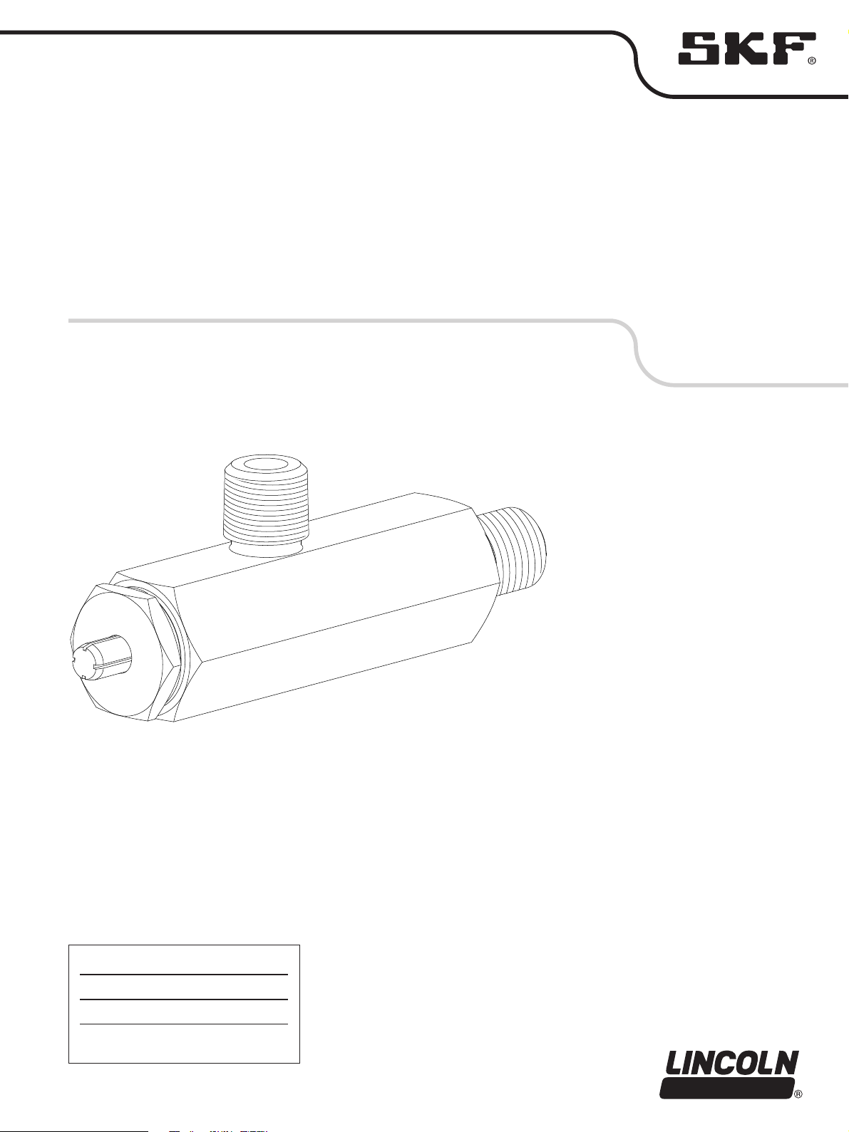
Description
Model and A are grease filters
for refilling small reservoirs of pumps such
as model QuickLub pumps.