Skibo PEQUEA 125P User manual

OperatOr'sManual
Models 125P, 175P, & 250P
Box Manure Spreader
2020, Part #990004

Contained in this manual is information that concerns the operation, adjustment and maintenance of the Pequea Model 125P,
175P, & 250P, spreader. Proper care and operation will assure you of a machine that will be as dependable as you expect it to
be. For many years of long service and performance, please have all operators read this manual carefully and keep it available
for ready reference.
These spreaders are intended to be towed by an agricultural tractor and powered by its PTO. These spreaders are designed to
haul and spread all types of manure, including pen packed, with a moisture content below 85%.
The Pequea dealer from whom you purchased this spreader will instruct you in its general operation. Your dealer's staff
of factory-trained service technicians will be glad to answer any questions that may arise regarding the operation of
your spreader.
A complete line of Pequea Machine replacement parts is carried by your dealer. These parts have been inspected at
Pequea and are manufactured with the same quality standards as has your spreader, in order to assure you of an
accurate fit.
The serial number of this spreader is located on the right front corner of the spreader. When you are writing or calling
for information or parts, please always refer to this number.
CAUTION: THIS SYMBOL IS USED THROUGHOUT THIS BOOK WHENEVER
PERSONAL SAFETY IS INVOLVED. TAKE TIME TO READ AND FOLLOW THE
INSTRUCTIONS. BE CAREFUL!
CAUTION: PICTURES IN THIS MANUAL MAY SHOW PROTECTIVE SHIELDING OPEN
OR REMOVED TO BETTER ILLUSTRATE A SPECIFIC FEATURE OR AN ADJUSTMENT.
REMEMBER TO CLOSE OR REPLACE ALL SHIELDING BEFORE OPERATING THE
MACHINE.
Improvements and Changes
Because Pequea Machine continually strives to improve all of our products, we reserve the right to make changes and
improvements wherever it is practical, without obligation to make those same changes or improvements to the equip-
ment sold previously.
To The Owner

1
SPECIFICATIONS................................................................................ 1
DECALS......................................................................................... 2
SAFETY/ CAUTION .............................................................................. 3
BEFORE USE .................................................................................... 4
OPERATION ..................................................................................... 5
LOADING ....................................................................................... 7
BEFORE LOADING . . . . . . . . . . . . . . . . . . . . . . . . . . . . . . . . . . . . . . . . . . . . . . . . . . . . . . . . . . . . . . . . . . . . . . . . . . . 8
FEED CONTROL POSITIONS...................................................................... 9
LUBRICATION ..................................................................................12
MAINTENANCE. . . . . . . . . . . . . . . . . . . . . . . . . . . . . . . . . . . . . . . . . . . . . . . . . . . . . . . . . . . . . . . . . . . . . . . . . . . . . . . . . 16
TROUBLESHOOTING ...........................................................................21
INDEX .........................................................................................22
DELIVERY REPORT..............................................................................23
WARRANTY....................................................................................24
Contents
Pequea Machine, Inc. reserves the right to change specifications without notice.
Specifications
Models 125 PTO 175 PTO 250 PTO
Capacity 125 Bu. 90 Cu. Ft. 175 Bu. 108 Cu. Ft 250 Bu. 128 Cu. Ft.
Overall Length 16'6" 17'8" 20'5"
Overall Width 76" 86" 92"
Loading Height 45" 44" 44"
Flared Width 56" 66" 72"
Box Width 47" 54" 60"
Box Length 128" 140" 160"
Box Height 23" 24-1/2"
Box Construction 10 Gauge High Steel Strength
Floor Construction High Density Poly Vinyl 3/4" T & G
Beater Paddles 8 Replaceable 10 Replaceable
Beater Diameter 26"
Drive PTO w/ 2 speed gearbox
Apron Chain 7/16" T-Rod
Spindle 2-1/8" 2-1/2", Optional Tendem Axle
Wheels/Tires 16 x 8-8 Bolt
10 x 16 Imp.
20 x 7-8 Bolt
10 x 20 O-Road
Jack 2K Bulldog
Weight w/ Tires 1850 lbs. 2220 lbs. 2620 lbs.
Tongue Weight Empty 110 lbs. 180 lbs. 200 lbs.
Tongue Weight
(Loaded Estimated)
325 lbs. 400 lbs. 450 lbs.
Horsepower Required 35 HP @ PTO 45 HP @ PTO 55 HP @ PTO
OPTIONS
Fine Spread Pan YES
Top Beater YES
End Gate YES
2
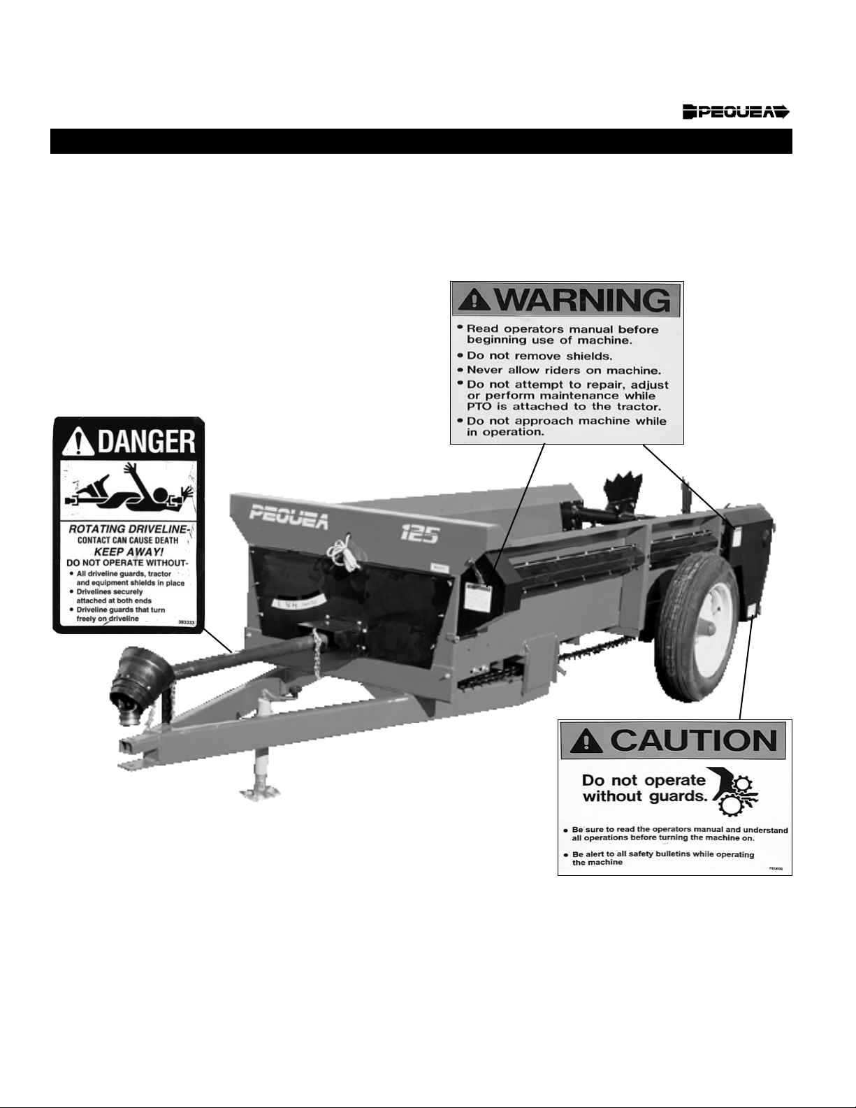
Safety Decals

3
MOST FARM IMPLEMENT ACCIDENTS CAN BE AVOIDED BY THE OBSERVANCE OF A FEW
SIMPLE SAFETY PRECAUTIONS.
1. DO NOT CLEAN, LUBRICATE OR MAKE ANY ADJUSTMENTS ON THE
SPREADER WHILE IT IS IN MOTION.
2. DO NOT START THE SPREADER UNTIL YOU KNOW EVERYONE IS CLEAR
OF THE MACHINE AND HAVE MADE SURE NO TOOLS ARE LYING ON THE
MACHINE.
3. DO NOT WORK AROUND THE UNIT IN LOOSE CLOTHING THAT MIGHT
CATCH IN ANY OF THE MOVING PARTS.
4. DO NOT ATTEMPT TO PULL MATERIAL FROM ANY PART OF THE
SPREADER WHILE IT IS IN OPERATION.
5. DO NOT GET OFF THE TRACTOR WHILE TRACTOR PTO IS ENGAGED.
6. REPLACE ALL SHIELDS AFTER LUBRICATION OR REPAIRS.
7. DO NOT ALLOW ANYONE TO RIDE ON SPREADER.
8. PARK ON LEVEL GROUND OR BLOCK WHEELS TO PREVENT SPREADER
FROM ROLLING.
Caution
This manual suits for next models
2
Table of contents
Other Skibo Farm Equipment manuals


Popular Farm Equipment manuals by other brands

Schaffert
Schaffert Rebounder Mounting instructions

Stocks AG
Stocks AG Fan Jet Pro Plus 65 Original Operating Manual and parts list

Cumberland
Cumberland Integra Feed-Link Installation and operation manual

BROWN
BROWN BDHP-1250 Owner's/operator's manual

Molon
Molon BCS operating instructions

Vaderstad
Vaderstad Rapid Series instructions


