Skibo PEQUEA SF5 User manual

Operator’s Manual
Vineyard & Orchard Spreader
Model SF5
THIS MANUAL MUST BE READ AND UNDERSTOOD BEFORE ANYONE OPERATES THIS MACHINE!

YOU MUST FILL OUT YOUR WARRANTY REGISTRATION
TO ACTIVATE YOUR WARRANTY AND TO QUALIFY FOR
PARTS AND SERVICE!!
To the Owner;
Thank-You for choosing a quality spreader from Pequea Machine, Inc. We
strive to give you the best equipment and the best level of service of any
company. With a little care and maintenance this machine will do your work
for you for many years. In this manual, we make an eort to get you better
acquainted with the spreader so you can achieve maximum performance.
We design and build all of our equipment with the end user in mind so we
welcome any suggestions or ideas for improvement.
Please take a few minutes to ll out the area below. This information will be
valuable to you when ordering parts or requesting service from your dealer.
Dealer Name:_____________________________
Dealer Phone Number:______________________
Service Manager/Technician:_________________
Model# and Description:_____________________
Serial Number:____________________________
Date of Purchase:__________________________

1
TABLE OF CONTENTS
INTRODUCTION 2
Serial Number 2
Specifications 2
SAFETY 3
General Safety Guidelines 3
Safety Decals and Reflectors 4
HITCHING 5
Tractor Requirements 5
Attaching to the tractor 5
TRANSPORT 6
Field Transport 6
Road Transport 6
OPERATION 7
General Operation 7
MAINTENANCE 8
General Maintenance 8
Wheel & Tire Maintenance 8
Wheel Bearing Maintenance 8
Grease Fitting Lubrication 9
Apron Chain Maintenance 9
Hydraulic System Maintenance 10
Gearbox Maintenance 10
OPTIONS AND ATTACHMENTS 11
Dual Conveyer Attachment 11
Oil Cooler Option 12
Dual Spinner Attachment 12
Conveyor Spinner Attachment 12
WARRANTY 13
NOTES 14

2
INTRODUCTION
Thank-You for choosing a Pequea Spreader. Your spreader is the result of years of research
and development work. This Operator’s Manual will familiarize the operator with the safety and
operation of the machine. Included are complete instructions for safe and ecient operation,
lubrication, and maintenance procedures. Understanding and following these procedures will
result in years of maximum performance from your Pequea Spreader.
Read entire manual before operating. Failure to follow the instructions outlined in this
manual may result in personal injury and/or damaged equipment, and could void the war-
ranty.
Serial Number
The serial number consists of ve numerical dig-
its and can be found on a small yellow sticker on
the left front corner of the spreader box (Figure 1).
Please use this number when requesting service,
seeking information, or ordering parts. For the oper-
ator’s convenience, space to record the serial num-
ber, model number, purchase date, and dealer has
been provided inside the front cover of this manual.
Specifications
All pictures and instructions in this manual assume that the right and left side
of the machine are that of someone standing behind the machine facing forward.
Standard Features SF5
Hopper Length 10’
Hopper Width (at top of Gable) 72”
Overall Width (max attachment) 215”
Overall Width (min attachment) 123-1/2 “
Overall Height 78”
Overall Length (without attachment) 184”
Overall Length (with attachment) 190”
Wheel Base (center to center) 58-3/4”
Tires 21.5L X 16.1 - 10 Ply on 8 Bolt Wheel
Material Capacity 4.5 cu. yd. (struck), 5.2 cu yd (heaped)
Payload 10,000 lbs
Empty Weight 3,600 lbs
Floor 3/8 x 12 UHMW
Floor Chain 3/4” Stainless Steel Mesh
Electronic Floor Shut-O Standard
Oil Cooler Optional
Dual Rear Conveyer Standard
Figure 1

3
SAFETY
This symbol precedes specic safety instructions throughout this manual. When read-
ing the manual pay close attention to the information that follows this symbol
FAILURE TO FOLLOW INSTRUCTIONS IN THIS MANUAL COULD RESULT IN PERSONAL
INJURY OR DEATH. READ ENTIRE MANUAL BEFORE OPERATING THE MACHINE!
Keep hands, feet, and clothing away from all moving parts.
Never allow riders on the spreader or the tractor.
Make sure that all persons are a safe distance away before moving the spreader or engaging
the spinners or conveyer.
When transporting the machine on public roads use the proper reectors, lights, and slow
moving vehicle signs required by local government agencies.
Stop the tractor engine, remove ignition key, and allow all mechanisms to stop before clean-
ing, adjusting, or lubricating the machine. Never attempt to pull material from any part of the
machine while it is running
Do not attempt to operate the spreader in areas with steep inclines, ditches, large rocks,
stumps or holes which may endanger the operator by upsetting the tractor and/or the spread-
er.
Avoid contact with hydraulic lines, they may be under extreme pressure or heat. Never go
near a hydraulic leak until the pressure has been relieved and the leaking has stopped. A high
pressure hydraulic leak can easily penetrate your skin and cause serious injury, gangrene or
death.
Avoid Making Sharp Turns and be sure to slow down to at most 6 mph when turning. Do not
turn on uneven terrain.
We at Pequea Machine, Inc. try to provide safety shield and guards wherever possible, however, it
is impossible to shield every area that could be dangerous. We will not be responsible for careless-
ness and misuse of any of our equipment.
General Safety Guidelines

4
SAFETY
Safety Decals and Reflectors
Decals and reectors are for the protection of yourself and others. If they are missing,
faded, or not readable, get replacements from your dealer immediately. Shown below are
some of the warning decals used on your spreader.
5
HITCHING
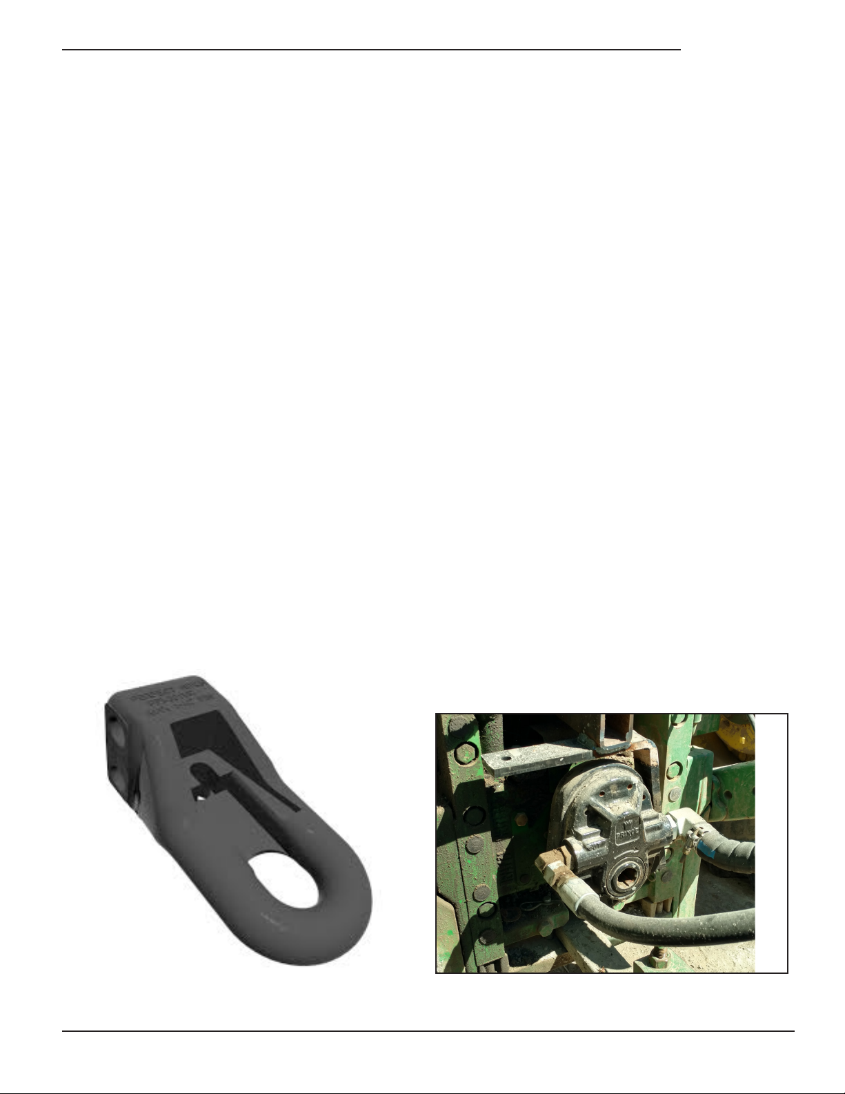
Attaching to the tractor
Line up the hole in the tractor draw bar with the hitch on the spreader and insert an approved hitch
pin with a locking device or safety clip. The spreader hitch (Figure 2) is attached with two bolts and
can be moved up or down to accommodate various draw bar heights.
Attach the safety chain(s) to the tractor draw bar.
Raise the jack drop leg and secure with drop leg pin.
Attach the hydraulic pump (Figure 3) to the tractor PTO output shaft and secure it to the tractor by
using a chain around the stabilizer bar. The chain will both keep the pump from rotating and will
keep it from sliding o the shaft.
Plug in the wiring for the lights (if lighting option has been installed) and make sure that the lights
and turn signals are working properly.
Tractor Requirements
Your spreader is equipped with a 540 RPM PTO hydraulic pump and must be matched with a tractor
that meets this requirement.
Figure 2 Figure 3

6
Field Transport
Never allow passengers on the spreader or the tractor.
Avoid tight turns to reduce the risk of loss of control.
Remain fully aware of the width and length of the spreader in relation to the objects you are pass-
ing, either stationary or moving.
Never travel at speeds over 10 MPH in the eld when loaded.
For level or rolling terrain, tractor weight must be at least 50% of gross loaded spreader weight.
For hilly terrain, road travel, or other adverse conditions, tractor weight must be equal to, or more
than the gross loaded spreader weight.
Road Transport
Adhere to all suggestions for transport in the eld listed above.
Follow all local regulations for moving agricultural equipment on public roads, especially those
related to reectors, SMV (slow moving vehicle) symbols and safety markers.
Be sure to use ashing lights at all times when transporting on public roads.
Slow down when turning to avoid instability and loss of control
Never travel at speeds over 20 MPH on the road.
TRANSPORT

7
General Operation
The apron and attachment functions on the spreader are driven hydraulically by the hydraulic pump
run by the tractor PTO.
The spreader is equipped with a hydraulic manifold with precision hydraulic valves (Figure 4) to ne-
tune both the attachment and apron chain speed to accommodate a wide range of spread patterns,
material density and much more. To change the settings, raise the glass cover and rotate the knobs to
the desired position.
The metering gate in the rear can be adjusted manually from 0-13” to control the depth of material
owing out onto the attachment. It is adjusted by turning the end gate wheel (Figure 5) to the desired
position and engaging the spring loaded lock pin. Turn the wheel clockwise to raise the gate and
counter-clockwise to lower it.
Figure 4 Figure 5
Lock Pin
The remote oor shut o switch (Figure 5) is
used to temporarily stop the apron chain while
the spinners are still rotating. This feature is
used when the operator makes a turn or pass-
es through an area where no material is to be
spread.
OPERATION
Figure 6

8
MAINTENANCE
General Maintenance
Check the spreader each time it is used for loose, bent, broken or missing parts or fasteners.
Never store material in the spreader in cold weather. The material could freeze against the sides
and oor of the spreader and cause severe damage to the apron drive system.
Clean the excess material o the sides of the spreader after each use. Fertilizer can be highly
acidic so if there are any scratches in the paint it will immediately begin to rust.
Wheel & Tire Maintenance
Check wheel lug torque once a month or after each period of use. Wheel lugs should be torqued
to 120 ft./lbs.
Check tire pressure before each period of use. Recommended tire pressure is stamped on the
sidewall of each tire.
Wheel Bearing Maintenance
Remove the hub and check consistency of the wheel bearing grease at least once a year. If the
grease is not the same consistency of fresh grease (either dry and caked or too thin) repack the
bearings with fresh grease. Retighten the spindle nut to 25 ft. lb., then back o one notch to insert
cotter pin.
The axle can be adusted by removing the bolts that
hold the axle hanger in place. Before adjusting the
axle, make sure the spreader is safely supported on
both sides. Keep in mind the weight of the spreader.
Always keep at least 6 bolts in to secure the axle
hanger in place.
Figure 7

9
Grease Fitting Lubrication
The spreader is designed to require minimal lubrication. However, the importance of sucient and
proper lubrication cannot be over emphasized as it is the best insurance against unnecessary
repairs and will greatly increase the life and performance of the machine.
Lubricate all the grease tting every six months or after 50 loads, whichever comes rst. Be care-
ful not to over grease the sealed bearings as too much grease could push out the seal and al-
low dust or debris to contaminate the bearing. One half of a stroke from a manual grease pump
should be sucient. Be sure to wipe all the dust and debris away from the grease tting before
greasing. If it is not clean you may force some dirt into the bearing.
Non sealed (friction) grease points will not be damaged by over greasing and should be kept vis-
ibly wet with grease. NOTE: There are friction grease points on the axle pivots. These are espe-
cially critical to be kept well greased at all times.
MAINTENANCE
Apron Chain Maintenance
Apply chain lube to the apron chain after each
period of use to lubricate and prohibit rust.
The apron chain may need to be tightened
periodically. The apron chain can be adjusted
by using the apron tensioner bolts (Figure 7)
on the front of the spreader. Be sure to ad-
just both sides equally so the chain is pulling
straight.
Figure 7

10
Figure 7
Hydraulic System Maintenance
The hydraulic system is virtually maintenance
free since it is a fully self contained system.
However, you may need to add oil to the res-
ervoir to keep it at the proper level. See Figure
7 below for recommended oil level. Recom-
mended oil type is universal tractor uid (UTF).
Required amount is approximately 30 gal.
Recommended
Oil Level
Gearbox Maintenance
The single motor drive gearbox ( Figure 9)
should be serviced once a year. Drain the oil
and then ll up to the check plug with new #90
gear oil. Required amount is approximately
16oz.
The oil lter on the main reservoir should be
changed periodically. Use only a 10 micron
lter designed for hydraulic oil.
Figure 9
MAINTENANCE
11
OPTIONS AND ATTACHMENTS
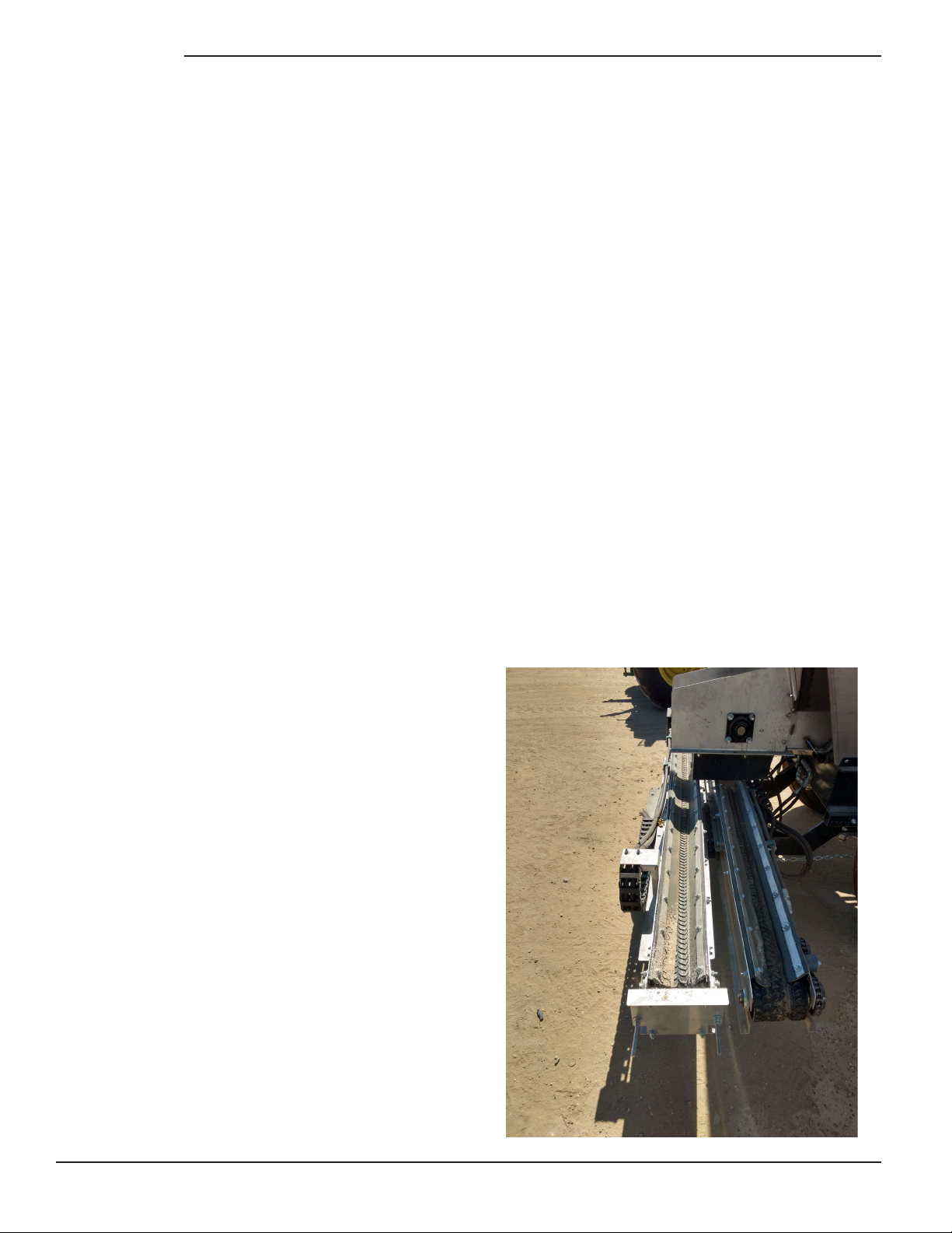
Dual Conveyer Attachment
The side conveyer option is to be used as a double row fertilizer applicator. The speed of the
conveyer belts determines the distance the material is thrown out beyond the end of the convey-
ers.
Ensure the conveyors slide in and out freely as well as pivot about the center freely. If the con-
veyors do not slide in and out freely make sure there is no debris on sliding rails. If conveyors
do not pivot about center point freely ensure there is no debris between under side of conveyor
mounting plate and plastic slide pads. Also, check the tightening nut under the conveyor mount-
ing plate frame is not too tight preventing it from rotating.
Dual conveyer attachment
To change width of conveyors pull sping pin on each conveyor to detent position and move to
desired width. Each hole location is approximately 6” appart
*Do not adjust or preform maintenance on
conveyors while belt is in motion
Conveyor belts may need to be tightened periodically. If pulleys are slipping and belts are not
moving, tighten take-up bearings evenly until they begin to move
Grease fittings are located on the bearings at the idler pulley end of each converyor. Follow
proper grease techniques as described above
Apply proper chain lube to conveyor chain drive before every use, located under the cover at
the ends of each conveyor

12
Oil Cooler Option
The Grape Spreader is equipped with a large capacity oil reservoir that is sucient to keep
the oil cool in most climates. However, if the spreader is being used in an extremely warm,
sunny climate the oil cooler option will help keep the oil temperature at a safe level.
OPTIONS AND ATTACHMENTS
Dual Spinner Attachment
The spinner attachment is used to distribute material evenly over a wide area behind and on both
sides of the spreader. Spread widths of up to 25’ can be achieved when the spinners are operat-
ing at full speed.
The spinner attachment can be moved forward or back to increase or decrease the spread width.
Conveyor Spinner Attachment
The spinner attachment is used to distribute material evenly over a wide area at the end of the
coveyor. Spread widths of up to 6’ can be achieved when the spinners are operating at full speed.
The spinner attachment can be moved forward or back to increase or decrease the spread width.

13
Pequea Machine’s Limited Warranty
Pequea Machine Company warrants to the original Purchaser all Machinery, Equipment, or Trailers
manufactured by it, to be free from defects in material and workmanship under normal use and ser-
vice. Its obligation under this Warranty shall be limited to replacement or repair of any parts thereof,
free of charge to the original Purchaser, at its place of business, provided, however, that the part(s)
to be replaced or repaired, shall within one (1) year after delivery to the original Purchaser, be dem-
onstrated to be defective; which determination shall be made by the Company. The said compo-
nents or parts must be returned through the Selling dealer or distributor directly to the Company with
all transportation charges prepaid. Notice of defect shall be furnished in writing to the Seller and to
the agent through whom the machinery was received, disclosing in full all known defects and failure
in operation and use, and reasonable time shall be given to the Seller to remedy any such defects
and failures. Failure to make such trial or give such notice shall be deemed an absolute acceptance
by the Buyer and satisfaction in full of this Limited Warranty.
This Warranty does not cover, under any circumstances, any parts, components, or materials which,
in the opinion of the Seller and Company, have been subjected to neglect, misuse, alteration, acci-
dent, or if repaired, with parts other than those manufactured by and obtained from Pequea Machine
Company.
This Warranty does not cover components which are already covered by a separate Warranty pro-
vided by the supplier of said parts or components.
The Company’s obligation under this Warranty is limited to repair or replacement, free of charge to
the original Purchaser, of any part which in judgment of the Company is defective. This Warranty
does not cover normal wear and tear.
THIS WARRANTY IS MADE EXPRESSLY IN LIEU OF ALL OTHER WARRANTIES, EXPRESSED
OR IMPLIED, INCLUDING ANY WARRANTY OF MERCHANTABILITY AND FITNESS FOR USE
AND PURPOSE AND OF ALL OTHER OBLIGATIONS OR LIABILITIES ON ITS PART AND ANY
IMPLIED WARRANTY. AND IT NEITHER ASSUMES NOR AUTHORIZES ANY OTHER LIABIL-
ITY IN CONNECTION WITH A SALE OF THIS MACHINE. THIS WARRANTY SHALL NOT APPLY
TO THIS MACHINE OR TO ANY PART THEREOF WHICH HAS BEEN SUBJECT TO ACCIDENT,
NEGLIGENCE, ALTERATION, ABUSE, OR MISUSE.
The Company makes no Warranty whatsoever in respect to accessories or parts not supplied by the
Company. The term “original Purchaser” as used in this warranty, shall be deemed that person for
whom the Machine, Equipment, or Trailer is originally supplied. This Warranty shall apply only within
the boundaries of the continental United States.
Under this Warranty, the Company cannot guarantee that existing conditions beyond its control will
not aect its ability to obtain materials or manufacture necessary replacement parts.
No one is authorized to alter, modify, or change the terms of this Warranty in any manner.
The Company warrants the Construction of the equipment sold herein and will replace at its ex-
pense for a period of (1) year from the date hereof, any parts which prove defective as determined
under the terms of this Limited Warranty.
WARRANTY

14
NOTES


200 Jalyn Drive
P.O. Box 399
New Holland PA 17557
Phone: 717-354-4343
Fax: 717-354-8843
E-mail: [email protected]
www.pequeamachine.com
Table of contents
Other Skibo Farm Equipment manuals


Popular Farm Equipment manuals by other brands

Schaffert
Schaffert Rebounder Mounting instructions

Stocks AG
Stocks AG Fan Jet Pro Plus 65 Original Operating Manual and parts list

Cumberland
Cumberland Integra Feed-Link Installation and operation manual

BROWN
BROWN BDHP-1250 Owner's/operator's manual

Molon
Molon BCS operating instructions

Vaderstad
Vaderstad Rapid Series instructions


