Skov FarmOnline+ Datalink Manual

FarmOnline+ Datalink
Technical User Guide
604432 • 2022-09-27 Software version 2.1
English For other language variants of this document we refer to:
Español Para otras variantes del idioma de este documento, visite:
Français Pour les versions dans d'autres langues de ce document veuillez consulter:
http://docs.skov.com/1253


FarmOnline+ Datalink
Technical User Guide 3
Product and Documentation Changes
SKOV A/S reserves the right to change this document and the product herein described without further notice.
In case of doubt, please contact SKOV A/S.
The date of change appears from the front and back pages.
Note
• All rights belong to SKOV A/S. No part of this manual may be reproduced in any manner whatsoever without
the expressed written permission of SKOV A/S in each case.
• All reasonable efforts have been made to ensure the accuracy of the information contained in this manual.
Should any mistakes or imprecise information occur in spite of this, SKOV A/S would appreciate being noti-
fied thereof.
• Irrespective of the above, SKOV A/S shall not accept any liability with regard to loss or damage caused or
alleged to be caused by reliance on any information contained herein.
• Copyright by SKOV A/S.

FarmOnline+ Datalink
Technical User Guide
1 Product description ....................................................................................................................................... 5
2 Product survey ............................................................................................................................................... 6
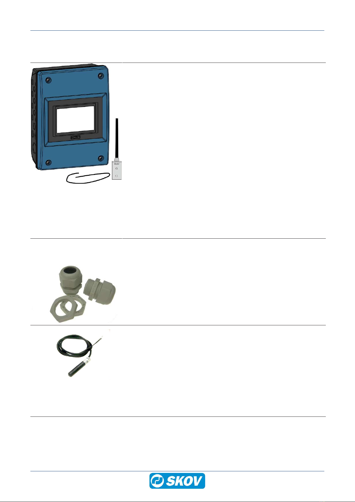
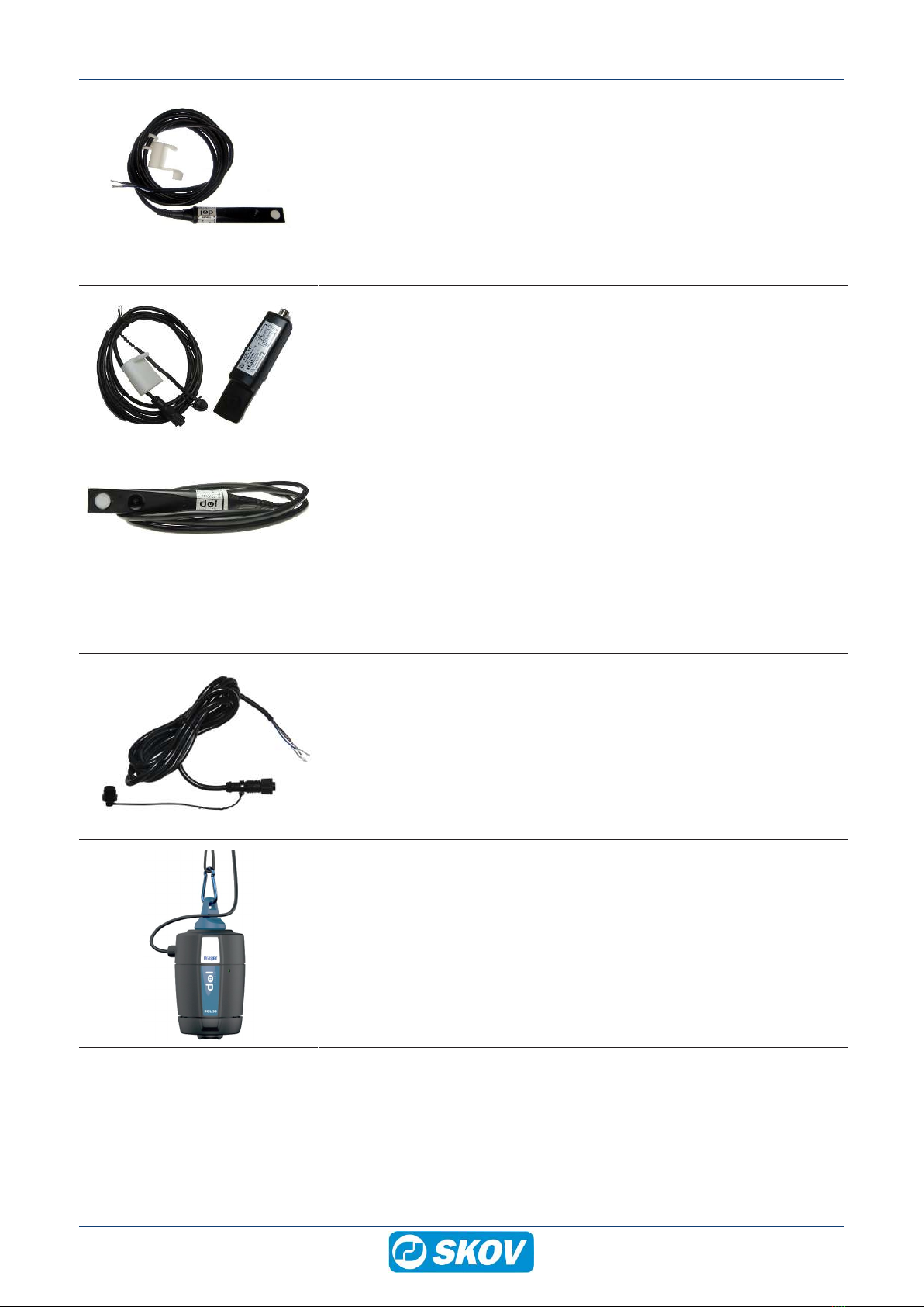
2.1 Accessories................................................................................................................................ 6
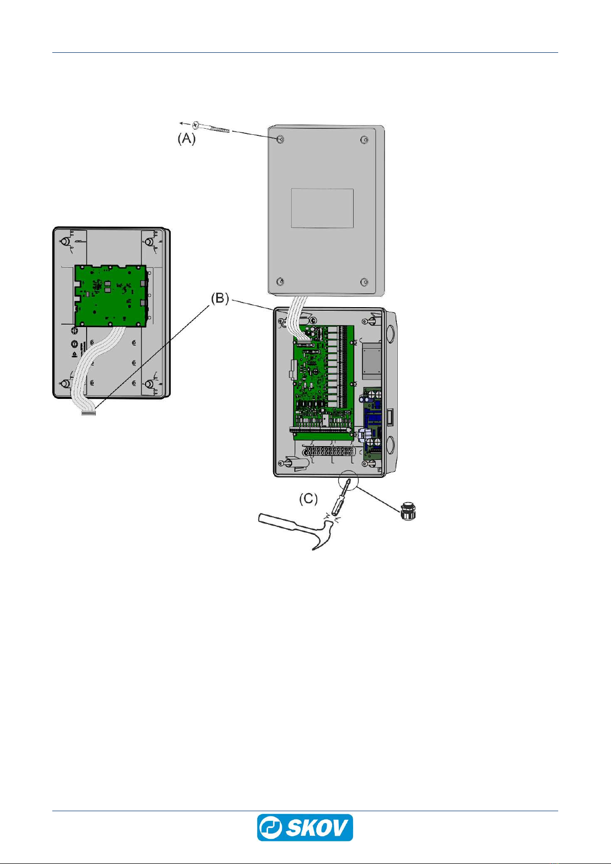
3 Mounting guide............................................................................................................................................... 9
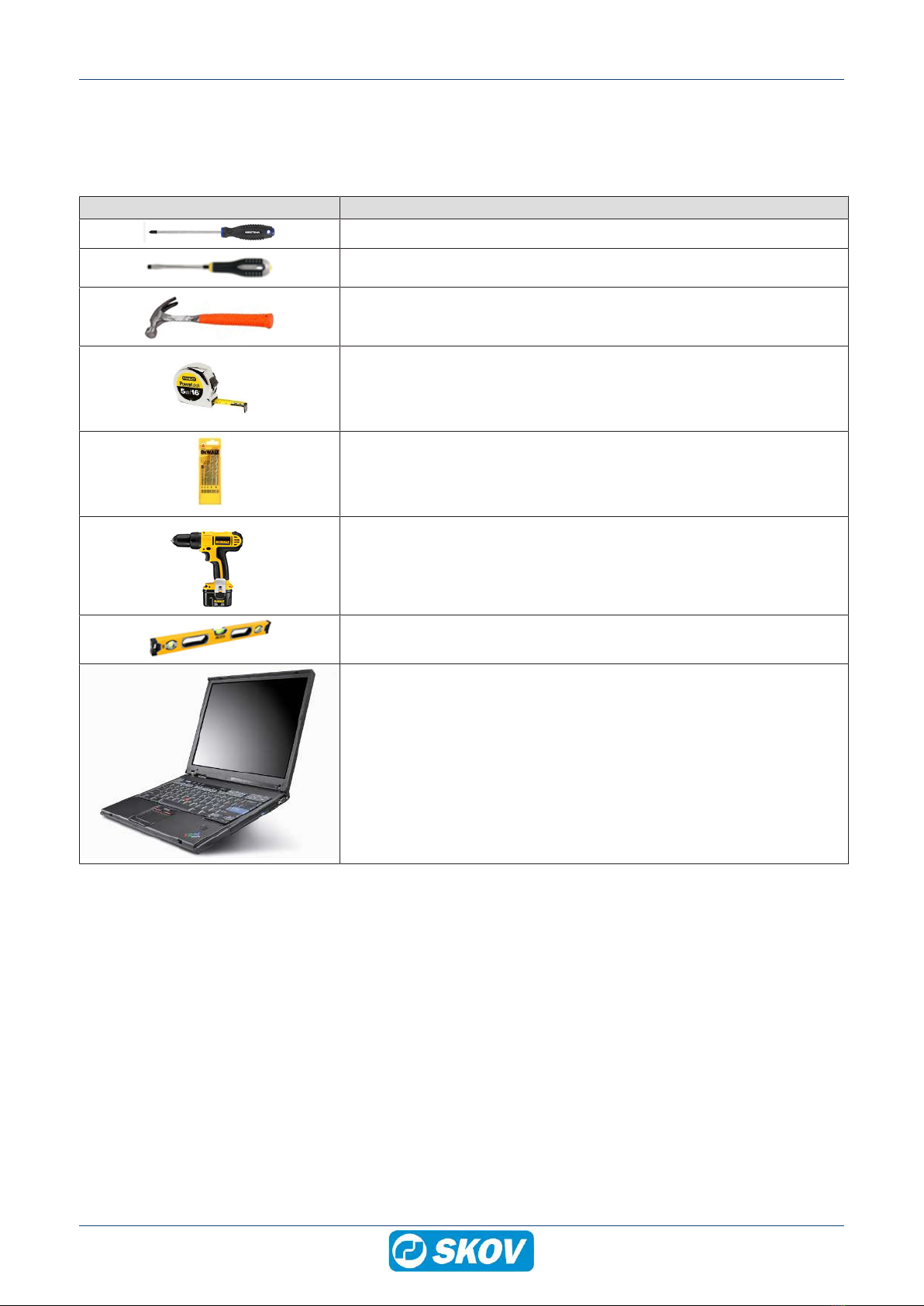
3.1 Recommended tools.................................................................................................................. 9
3.2 Mounting on the wall ............................................................................................................... 10
4 Installation guide.......................................................................................................................................... 12
4.1 Electrical connection............................................................................................................... 12
4.2 Connection of network ............................................................................................................ 12
4.3 Connection of external antenna ............................................................................................. 13
4.4 Connection of input sensors .................................................................................................. 14
4.5 Connection of power supply................................................................................................... 16
4.5.1 Setting the supply voltage on the power supply......................................................................... 16
5 Setup ............................................................................................................................................................. 17
5.1 Setup FarmOnline Datalink's internet connection................................................................ 17
5.2 Setup FarmOnline+ Datalink as a device in FarmOnline+ via MySKOV ............................. 18
5.3 Enter the device key from FarmOnline+ in FarmOnline+ Datalink...................................... 18
5.4 Setup of input sensors on FarmOnline+ Datalink ................................................................ 19
5.5 Add location of input sensors in FarmOnline+..................................................................... 20
5.6 Settings..................................................................................................................................... 21
6 User guide..................................................................................................................................................... 22
6.1 Batch ......................................................................................................................................... 22
6.2 Input sensors ........................................................................................................................... 24
7 Maintenance.................................................................................................................................................. 25
7.1 Recycling/Disposal .................................................................................................................. 25
8 Troubleshooting instructions ..................................................................................................................... 26
9 Technical data .............................................................................................................................................. 27

FarmOnline+ Datalink
Technical User Guide 5
1 Product description
This User's Guide deals with the installation and connection of FarmOnline+ Datalink.
The structure of the manual follows the required work routines. By following the instructions of the manual, you
will go through all steps in the correct order.
FarmOnline+ Datalink is developed for data collection in various parts of the agricultural industry. This can be
automatic collection from input sensors e.g. temperature sensors and/or the user's manual entries of data. The
collected data is then made available to the digital service FarmOnline+.
DOL 12
DOL 114
DOL 114
DOL 119
Figure1: Example of a system with FarmOnline+ Datalink.

FarmOnline+ Datalink
6 Technical User Guide
2 Product survey
131545 FarmOnline+ Datalink EU
131546 FarmOnline+ Datalink CN
131547 FarmOnline+ Datalink AP
131548 FarmOnline+ Datalink NF
131549 FarmOnline+ Datalink LA
Inputs (11). Of which 5, where DOL 12 can be connected and 6 where wa-
ter meter/feed counter can be connected.
The device is supplied in 5 variants with different types of modems intended
for different geographical areas.
EU: Europe, the Middle East and Africa
CN: China and India
AP: Asia and the Pacific region
NF: North America
LA: Latin America
Order the correct version for your country. If necessary see 4G Modem
Country list.
Supplied with modem with SIM card, external antenna and 10 meter an-
tenna cable.
Installation cables are not supplied.
2.1 Accessories
134703 M25 cable glands (30 pcs.)
Plastic gland and plastic nut for mounting in a house controller or box. Can
be used when mounting cables in size ø9-17 mm.
140200 DOL 12 temperature sensor, 1.4 m cable
S140200A DOL 12 temperature sensor, 5 m cable
An outside temperature sensors are supplied with the climate controller as a
standard.
Order the required number of sensors for registration of inside temperature.
The climate controller is not supplied with a inside temperature sensor.
In large houses, up to eight extra temperature sensors can be connected,
resulting in an average measurement by several sensors per zone.
When using pad cooling, order additional DOL 12 sensors if an alarm is re-
quired for no cooling at pads - e.g. one per pump.

FarmOnline+ Datalink
Technical User Guide 7
140252 DOL 114 humidity and temperature sensor, 2 m cable
140253 DOL 114 humidity and temperature sensor, 5 m cable
The DOL 114 is a dual-purpose temperature and humidity sensor that can
be used for monitoring the livestock house relative air humidity and temper-
ature.
The DOL 114 is a high-quality sensor which is especially useful under par-
ticularly harsh conditions and in areas of high air humidity.
The DOL 114 comes with a protective cap.
140331 DOL 119 CO2 sensor 5000/10000 PPM
Sensor for measuring the CO2 content in the air. Supplied with a M12 plug
and sealing plug as well as protection cap for DOL 119.
140266 DOL 16 light sensor 0-100/1000 LUX 0-10V M12 plug
140268 DOL 16 light sensor 0-100/1000 LUX 0-10V
Output 1: 0-100 lux. Output 2: 0-1000 lux.
The sensor can be used to measure the light intensity for main light and
slave light, respectively.
Select the type of sensor that corresponds to the current brightness in the
livestock house (measuring area).
Sensor with fixed cable.
140269 Cable 2 m M12 plug incl. sealing plug
2 meter cable for DOL 119/DOL 16 with M12 plug and sealing plug.
140247 DOL 53 ammonia sensor
140236 DOL 53 dust filter (5 pcs)
DOL 53 measures levels of ammonia in the air in livestock house.
Can be used for registration of the ammonia levels in the air.

FarmOnline+ Datalink
8 Technical User Guide
140333 DOL 18 v2 elec. sub-pressure sensor 100 Pa
Sensor for measuring the pressure level in the house.
DOL 18 hose set must be ordered separately.
140235 DOL 18 hose set
Hose set for DOL 18 electronic sub-pressure sensor.
300085 Transparent plastic hose ø7x5
3 meters.
To be used if additional plastic hose is needed.
437672 Extension nipple & 5/7 PVC tube set
Extension nipples must be ordered if another hose type than
300085/140235 is used.
380101 Bracket for DOL 16/104/114
Mounting brackets are used if the sensor is to be mounted in an accurate
position.
413232 House board
For mounting of climate sensors.

FarmOnline+ Datalink
Technical User Guide 9
3 Mounting guide
3.1 Recommended tools
Below is a list of the tools recommended for the installation.
Item Description
Crosshead screwdriver
Screwdriver straight slot (2 pcs.)
Hammer
Tape measure
Drill kit
Cordless drill
Spirit level
PC with internet connection

FarmOnline+ Datalink
10 Technical User Guide
3.2 Mounting on the wall
The FarmOnline+ Datalink must be installed where it is not exposed to frost or direct sunlight.
1. Loosen the screws (A) that hold the front panel in place.
2. Lift out the front panel.
3. Be careful not to pull the flat cable (B), as this may damage the connector.
4. Knock out the number of knock-out pieces (C) in the cabinet base needed for input sensors and mains sup-
ply.
5. Remember to use M25 cable glands in order to obtain a tight cable connection.

FarmOnline+ Datalink
Technical User Guide 11
43 CM
10 CM
1. Place the display (D) at eye level for the daily user.
2. Remember free space:
- above the cabinet (43 cm), so that the front panel can be placed on top of the cabinet base (E) during ser-
vicing.
- below the cabinet (10 cm) to enable room for cable connections.
3. Mount with ø5mm screws (F).

FarmOnline+ Datalink
12 Technical User Guide
4 Installation guide
The FarmOnline+ Datalink must be connected to cables for input sensors power supply and any Ethernet net-
work.
4.1 Electrical connection
Installation, servicing and troubleshooting of all electrical equipment must be carried out by quali-
fied personnel in compliance with the applicable national and international standard EN 60204-1
and any other EU standards that are applicable in Europe.
The installation of a power supply isolator is required for each motor and power supply to facilitate
voltage-free work on the electrical equipment. The power supply isolator is not included.
4.2 Connection of network
If a Local Area Network (LAN) is available, we recommend connecting the device to this to obtain Internet con-
nection. Otherwise the device will use the built-in 4G modem to communicate via the Internet.
Connect an Ethernet cable to the network connector LAN1, which is located on the CPU module in the cabinet
cover.
Figure2: Cabinet cover with CPU module.

FarmOnline+ Datalink
Technical User Guide 13
4.3 Connection of external antenna
In order to ensure optimum conditions as regards quality and stability of the connection, it is important to comply
with all requirements as well as specifications.
(A)
(B)
(C)
(C)
(A)
(B)
Top of the 4G modem
At mounting, it should be ensured that:
• The antenna is mounted in the open as high up as possi-
ble.
• Metal objects placed at the same height as the antenna
should not be within a range of 1 meter.
• The antenna is fixed.
• The cable is properly attached.
• The cable is bent as little as possible (not less than a ra-
dius of 25mm).
• The cable is not flattened or somehow damaged.
Be aware that metal roof surfaces can reduce the signal of
the antenna. Trees, silos, exhaust units, etc. also degrade
the signal strength.
1. Connect cable from 4G modem (USB) to CPU (USB1)
(A).
2. Connect the wire 24 V DC (B). REMEMBER to connect
to ground.
3. Connect the cable to the antenna (C) in the Cellular
socket on the 4G modem.

FarmOnline+ Datalink
14 Technical User Guide
4.4 Connection of input sensors
The FarmOnline+ Datalink can be connected to up to 11 input sensors of the following type:
Input sensor Limit value (gives direct data transmission)
DOL 114 (humidity) 1 %
DOL 114 (temperature) 0.5 °C
DOL 12 (temperature) 0.5 °C
DOL 16 (light intensity)
DOL 18 (pressure)
DOL 119 (CO2) 20 ppm
DOL 53 (NH3) 1 ppm
Feed counter 0.1 t
Water meter (max. 6 pulses per second) 0.1 m3
It collects data from input sensors once every minute.
It sends data at least once every 5 minutes. However, a value is sent immediately if the difference to the last
read value is greater than the limit value.
Cross section Length
1.5 mm20-200 m
2.5 mm2201-330 m
4.0 mm2331-530 m
Table1: Cable dimensions for DOL 119, DOL 114, DOL 53, DOL 18 and DOL 12 (24V DC)
Cross section Length
0.82 mm20-100 m
Table2: Cable dimensions for DOL 16

FarmOnline+ Datalink
Technical User Guide 15
Figure3: Connections to main I/O
B2 B2-A B2-B B5 B7 B9 B15 B15-A B15-B B18 B20
DOL 12 XXX XX
Water meter X X X X X X
Feed counter X X X X X X
DOL 114
(Temp & RH)
XXXXXXXXXXX
DOL 53 (NH3) XXXXXXXXXXX
DOL 119
(CO2)
XXXXXXXXXXX
DOL 16 (LUX) XXXXXXXXXXX
DOL 18 (PA) XXXXXXXXXXX
Table3: Connection options for each type of input sensor
Note that the DOL 12 temperature sensor can only be connected to B4/B5, B7/B8, B9/B10, B17/18 or B20/21.
It is recommended to use the same 24V supply (B11) for water meter and feed counter.
Also see the documentation supplied with the input sensors for connection.
Note which input each sensor gets, as it will be used later.

FarmOnline+ Datalink
16 Technical User Guide
4.5 Connection of power supply
(A)
(B)
1. Run the power cable through a cable gland (A). Make sure that it fits tightly by means of a sealing ring.
2. Connect the wires to the 230 V power supply input L-N-PE (B).
4.5.1 Setting the supply voltage on the power supply
Before you connect supply voltage, it is important to set the voltage in the power supply so that it
corresponds to the voltage level in the local house.
1. Set the voltage in the power supply.
2. Connect the supply voltage.
200-230 V Leave the plug in (factory setting)
100-115 V Move the plug to 100-115 V

FarmOnline+ Datalink
Technical User Guide 17
5 Setup
5.1 Setup FarmOnline Datalink's internet connection
The FarmOnline+ Datalink´s internet connection must be setup via a wired LAN connection.
As a backup, a wireless internet connection can be set up via a 4G modem.
See section Connection of network [}12] and Connection of external antenna [}13] for cable connection.
Press to go to the connection setup page.
The menu displays the current status and gives access to set-
ting up the Internet connection.
Type
Wide area
network (LAN1)
Recommended
Select DHCP or Static.
DHCP is the default setting. This means that no further settings must be made as the sys-
tem automatically selectsIP address, Net mask and Gateway IP address.
When selecting Static the Net mask and Gateway IP address must be set manually.
Modem stick Log display of the modem status which will show, for example, the time the modem was
connected or when it was disconnected.
The log can also be used in connection with error tracing in the network.
We recommend using Static setup.

FarmOnline+ Datalink
18 Technical User Guide
5.2 Setup FarmOnline+ Datalink as a device in FarmOnline+ via
MySKOV
Following is required:
• User profile with the role Admin in MySKOV (performed by the supplier).
• Company setup in MySKOV, loading of license (performed by the supplier).
• Farm and associated houses created in MySKOV.
1. Open an Internet browser on a PC and go to MySKOV (my.skov.com). Log in with a user profile that has an
Admin role.
2. Click the (Connection) and select the tab Farms.
3. Check if a location (a farm and a house) has already been created to which data links can be assigned. Oth-
erwise this must be done now in FarmOnline+ | Farms | Add farm.
4. Select the tab Devices click Add device and enter the required data.
5.3 Enter the device key from FarmOnline+ in FarmOnline+ Datalink
When the device is added in FarmOnline+, a unique device key is created, which must be inserted in FarmOn-
line+ DataLink.
1. Write down the device key.
2. Press on the FarmOnline+ Datalink.
3. Open the menu item Datalink. Enter the device key.

FarmOnline+ Datalink
Technical User Guide 19
5.4 Setup of input sensors on FarmOnline+ Datalink
Press to go to the page for setup of input sensors.
Press
(A)
(B)
A Tool to edit, move or delete of an input sensor.
B Tool to add a new input sensor.
Select name, type of input sensor and which terminal it is con-
nected to. It is important to select the correct terminal.
Feed counter and water meter
In addition, set a value per pulse for the feed counter and water
meter under Calibrate sensor.
I/O status
Press and select the menu I/O-status. The menu shows
the current status and gives access to an overview of the con-
nected input sensors with a display of where they are con-
nected and what their current values are.
The overview can be used in connection with trouble shooting
the input sensors.

FarmOnline+ Datalink
20 Technical User Guide
5.5 Add location of input sensors in FarmOnline+
1. Open an Internet browser on a PC and go to MySKOV.
2. Click the (Connection) and select the tab Sensors.
All input sensors connected to the datalink are shown here.
3. Click (Assign Sensor) for each individual input sensor and assign it a location.
Data from the input sensor will only be visible in FarmOnline+ when a new batch has been registered (Move in /
Batch).
This manual suits for next models
10
Table of contents
Other Skov Farm Equipment manuals
Popular Farm Equipment manuals by other brands

sitrex
sitrex GS 160 Use and maintenance

Croplands
Croplands WEED-IT Quadro Transport Unloading & Setup Guide

NOREMAT
NOREMAT Optima 51 Operator's manual

MacDon
MacDon M1170NT5 Unloading and assembly instructions

ADAPCO
ADAPCO Guardian 95 G4 Operator's manual

Maschinenfabrik Kemper
Maschinenfabrik Kemper C2200 Operator's manual