Tru-Test WaterPro 2 User manual

1
USER GUIDE
Capacity Herd capacity Drinking height Net weight
7 gal
27 L
75 horses, 75 beef
75 horses, 75 beef
21.65 inches
550 mm
59.5 lbs
27 kg
Capacidad Rebaño máx. Altura para beber Peso neto
7 galones
27 l
75 caballos, 75 reses
75 caballos, 75 reses
21,65 pulgadas
550 mm
59,5 libras
27 kg
English ..............................................................................................................................................................2
Español ...........................................................................................................................................................19

2
Contents
Safety warnings.........................................................................................................................................................................3
Warranty registration................................................................................................................................................................3
Before you start.........................................................................................................................................................................4
WaterPro2 measurements.................................................................................................................................................4
Basic concrete slab measurements....................................................................................................................................4
Concrete and tank hole alignment....................................................................................................................................5
Unpacking the box....................................................................................................................................................................5
Recommended parts .........................................................................................................................................................5
Recommended tools..........................................................................................................................................................5
Included parts ...................................................................................................................................................................6
Installation ................................................................................................................................................................................7
Cross-section of final installation ......................................................................................................................................7
Step 1: Preparing the site.................................................................................................................................................8
Step 2: Installing the water supply lines...........................................................................................................................8
Step 3: Installing the electric service for the heat immersion cable.................................................................................. 9
Step 4: Installing a thermal earth tube.............................................................................................................................9
Step 5: Pouring the concrete slab ....................................................................................................................................9
Step 6: Preparing the vertical water supply line and checking for leaks ........................................................................10
Step 7: Preparing the tank .............................................................................................................................................12
Step 8: Installing an immersion heater (optional) ..........................................................................................................12
Step 9: Filling the tank...................................................................................................................................................12
Step 10: Affixing the tank to the concrete slab...............................................................................................................12
Pressure and flow capacity......................................................................................................................................................13
Using the shut-off valve as a pressure reducer................................................................................................................13
Recommendations...................................................................................................................................................................14
Split fence measurements ...............................................................................................................................................14
General maintenance......................................................................................................................................................14
Troubleshooting ......................................................................................................................................................................15
Spare parts..............................................................................................................................................................................16
Valve and float................................................................................................................................................................17
Product warranty.....................................................................................................................................................................18
Terms and conditions for Livestock Automatic Watering products..................................................................................18

3
Safety warnings
Please read this guide carefully before you install the WaterPro2.
Warning!
The installation of your WaterPro2 must be performed with rigorous adherence to national and local
plumbing and electrical codes. Failure to install or maintain your unit to the code standards may result in personal
injury, death or loss of livestock.
Warranty registration
Please supply us with your details so that we can register your product and keep you informed of any important product
updates. See more at livestock.tru-test.com/en-us/livestock-waterer-warranty-registration-form
© 2017-2018 Tru-Test Limited.
All product names and brand names in this document are trademarks or registered trademarks of their respective holders.
No part of this publication may be photocopied, reproduced, stored in a retrieval system, or transmitted in any form or by any
means, electronic, mechanical, photocopying, recording or otherwise without the prior written permission of Tru-Test Limited.
Product specifications may change without prior notice.
For more information on other quality Tru-Test Group brands and products, visit www.tru-testgroup.com
Tru-Test Inc.
528 Grant Road
Mineral Wells
Texas 76067
UNITED STATES
Toll free: 800 874 8494
Fax: 940 327 8048
Although the information presented in this product document is believed to be accurate and reliable, no responsibility for
inaccuracies can be assumed by Tru-Test Limited. Tru-Test Limited reserves the right at any time to change characteristics or
specifications without notice.
All trademarks with an * are neither owned by nor licensed to Tru-Test Limited and belong to their respective owners.
833400 Issue 5 1/2018

4
Before you start
Measure out the dimensions of the concrete slab that you will need.
Length x Width x Overall Height Length x Width x Overall Height
WaterPro2 39.2 x 22.1 x 28.7 inches 996 x 563 x 730 mm
WaterPro2 measurements
Basic concrete slab measurements

5
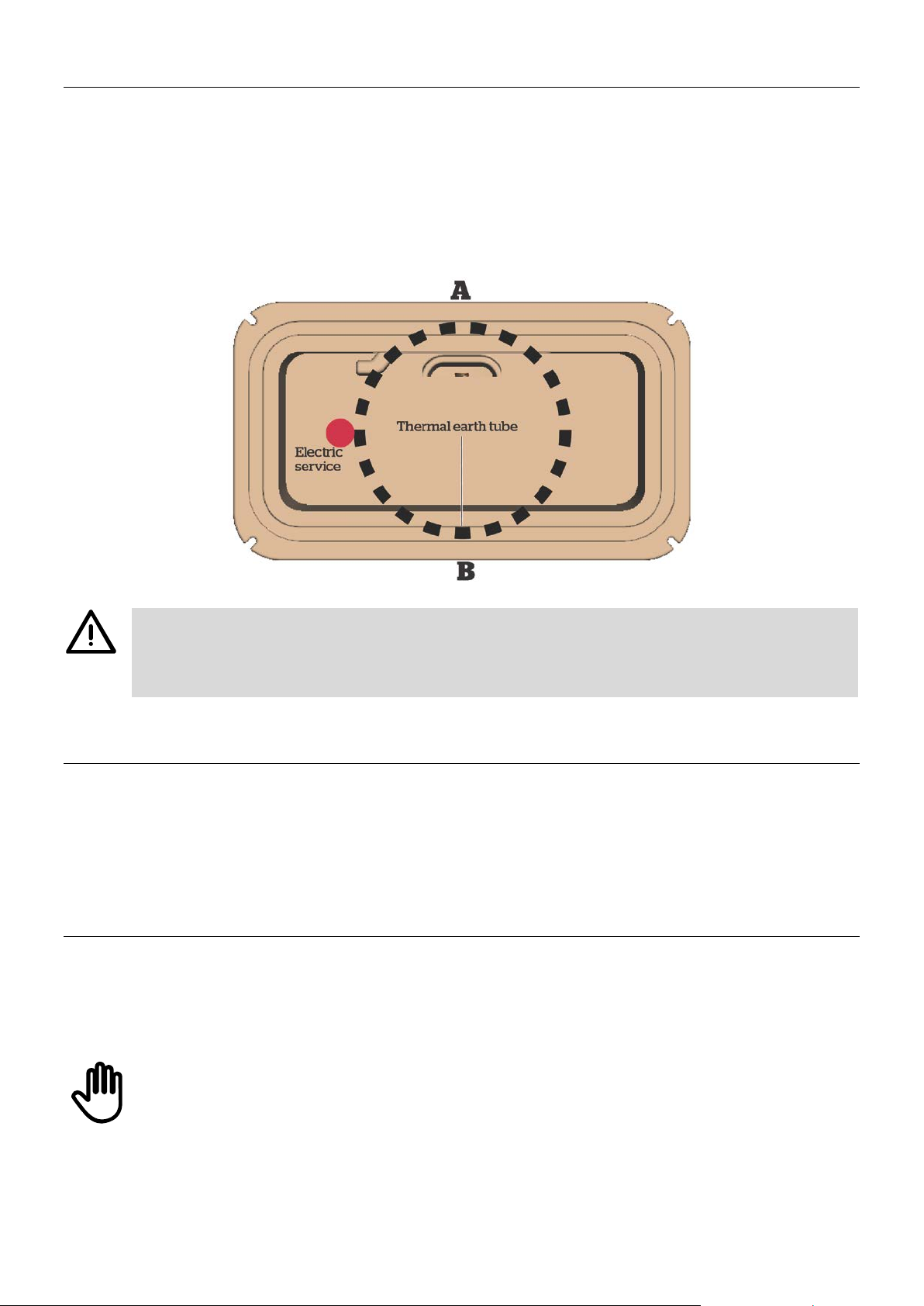
Concrete and tank hole alignment
Check your measurements to ensure that the opening on the bottom of the tank aligns with the thermal earth tube
placement in the concrete. The opening on the bottom of the tank is off center. Ensure that the water supply lines
are not touching the sides of the thermal earth tube.
Underneath the WaterPro2
Unpacking the box
Recommended parts
•In colder climates, we strongly recommend the use of one or more thermal earth tubes to help keep the vertical water
supply line from freezing. The thermal earth tube(s) must be long enough to extend 1 foot (305 mm) below the normal
frost line.
•½ inch NPT male fitting to connect the vertical water supply line to the ½ inch flex line inside the tank. If your vertical
water supply line is more than ½ inch in diameter, you will also need an adapter.
•250 W immersion heater for heating water in the tank (optional).
Recommended tools
•Adjustable wrench
•Pipe wrench
•Measuring tape
•Utility knife
•Level
•Hammer drill
•½ inch masonry bit
•Hammer
•½ inch ratchet wrench
•Caulk

6
Included parts
Get to know the parts of the WaterPro2 before you install it. Contact us on 800 874 8494 if anything is missing.
Images are indicative of shipped part and not shown to scale.

7
Installation
Cross-section of final installation
The WaterPro2 is designed to provide reliable fresh water to your livestock all year round.
When installing the WaterPro2 pay attention to the following areas:
•Choose a location where the tank will be sheltered from the elements.
•The vertical water supply line and the horizontal water supply line should all be installed to reach more than 1
foot (305m) below the usual frost line.
•The concrete slab should have a 4 inch (102 mm) by 18 inch (457 mm) apron from the tank to the concrete
edge.
•Ensure that the placement of the water and electric access hole in the concrete aligns with the anticipated
placement of the water and electric access cavity of the waterer.
•Make sure your vertical water supply line protrudes 10 inches (254 mm) above the concrete slab.
•The water supply line should be centered in the thermal earth tube (if using) to help discourage frost formation.
•To be effective, the thermal earth tube(s)* must be installed to reach at least 1 foot (305 mm) below the usual
frost line.
*Note that more than one thermal earth tube may be required.
•Care should be taken to ensure the electric service below ground is installed outside of the thermal earth tube.
•It is recommended to caulk the base of the tank to prevent moisture and wind penetration.
In addition to the shut-off valve located inside the unit, we strongly recommend that a second, external shut-off valve
be installed outside of the concrete.

8
Have you turned off the water?
Step 1: Preparing the site
aChoose a location that is easily accessible by livestock and sheltered from the elements.
bCheck the measurements of your WaterPro2 against the size of the concrete slab you need. See
Concrete and tank hole
alignment
on page 5.
cIn the WaterPro2, the access cavity for the vertical water supply and electric supply is off center. Align the thermal earth
tube so that the vertical water supply is as close to the center of the tube as possible. Take care to ensure that the vertical
water supply line does not touch the sides of the thermal earth tube as this will cause the supply line to freeze. See
Concrete and tank hole alignment
on page 5.
Check that you have aligned the hole in the concrete with the access cavity under the WaterPro2.
Step 2: Installing the water supply lines
aThe horizontal water supply line should be at least 1 foot (305 mm) below the frost line.
bStrongly recommended: If installing a shut-off valve, install it on the horizontal water supply line leading up to the tank
and ensure it is located outside of the perimeter of the concrete slab.
cThe vertical water supply line should be a ½ inch in diameter to connect to the horizontal water supply line. If your vertical
water supply line is larger than ½ inch, you will also need an adapter.
Ensure that the vertical water supply line is cut at least 10 inches (254 mm) above the ground. You
will cut it to a more precise length in Step 6.
9
Step 3: Installing the electric service for the heat immersion cable
aIf you are installing the WaterPro2 in an area that experiences freezing temperatures, you may wish to install an immersion
heater (part 832381).
bArrange for your electrician to install the electric service around the same time you are installing the water supply lines.
cInstall the electric service outside of the thermal earth tube on the horizontal side under one of the water reservoirs. Do
not install on either A or B side below as there is a risk that the electric service will not be located under the unit as the
diameter of the thermal earth tube almost spans the entire width of the unit.
Warning!
The electric service should only be installed by a qualified / certified electrician. The electric supply
must run outside of the thermal earth tube, be properly grounded, and be installed and maintained in accordance
with all applicable electric codes.
Step 4: Installing a thermal earth tube
aInstall a thermal earth tube around the vertical water supply line. It must be at least 1 foot (305 mm) below the frost line.
Ensure that the vertical water supply line is centered within the thermal earth tube.
bIf you are in a colder climate, we recommend an additional thermal earth tube be used to extend its length by at least
another foot (305 mm).
Step 5: Pouring the concrete slab
aBefore you pour the concrete, check that you are using the correct measurements for your WaterPro2. See
Concrete and
tank hole alignment
on page 5.
bThe thermal earth tube should be flush with the top of the concrete slab.
Do not pour concrete into the thermal earth tube or fill the space with dirt or
any other material, as it will prevent
warm air below the frost line from circulating around the vertical water supply line, and will cause the water line to
freeze.

10
Critical step please follow these instructions carefully
Step 6: Preparing the vertical water supply line and checking for leaks
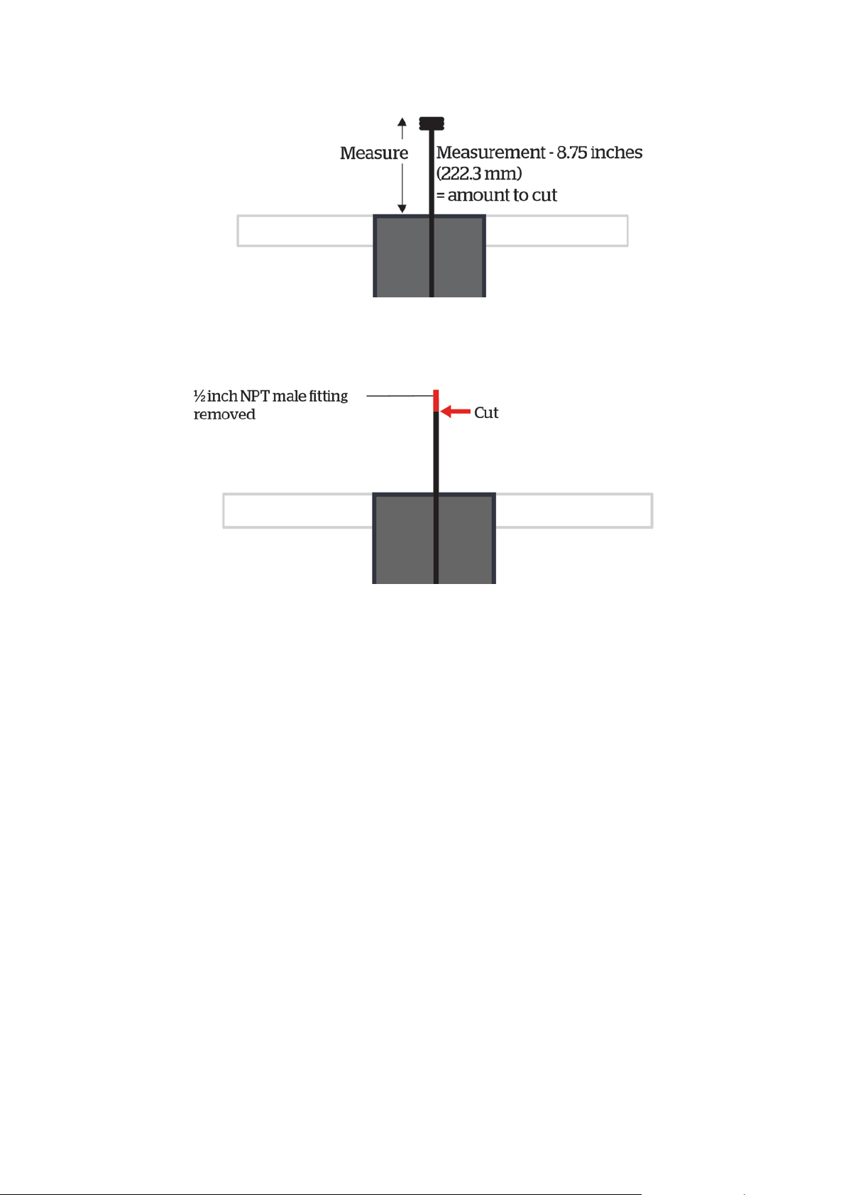
In Step 2, the vertical water supply line was cut to be approximately 10 inches (254 mm) above the concrete slab. In this step,
you will add the NPT fitting and any adapters needed first, measure and then cut it to a precise length. For the easiest
installation, the vertical water supply line with all fittings and adapters should measure exactly 8.75 inches (222.3 mm) from
the top of the concrete to the top of the last fitting.
When completed, the installation should look like this:
To achieve this, please closely follow these instructions:
aAttach any adapters that are needed to enable the vertical water supply line to receive a ½ inch NPT male fitting. Do not
glue the adapter to the line.
bAttach a ½ inch NPT male fitting onto the end of the vertical water supply line. Do not glue the fitting to the line.
cWith the NPT fitting and all adapters attached, measure the length of the line from the top of the concrete to the top of
the fitting.
11
dTake the measurement and subtract 8.75 inches (222.3 mm) from this number. This is the amount of pipe you will need to
cut.
eRemove all adapters and fittings from the vertical water supply line.
fFrom the top down, mark the pipe with the measurement you need to cut.Cut the pipe.
gAttach any adapters and the ½ inch NPT fitting and re-measure. The distance from the top of the concrete to the top of the
NPT fitting should now measure 8.75 (222.3 mm) inches. Once this is confirmed, permanently attach your adapters and
fittings.
hTurn on the water supply to flush any dirt and debris through the water supply line. Turn off the water supply.
iTo test for leaks throughout the entire system (including the valve), remove the valve and mount assembly, attach the ½
inch flex line to the shut-off valve and to the vertical water supply line. (The ½ inch flex line is pre-installed on some
units). Turn on the water and check for leaks. Turn off the water.
jUndo the shut-off valve from the ½ inch flex line.
kSlide the water supply insulation tube over the ½ inch flex line and vertical water supply line. Both should be insulated.

12
Step 7: Preparing the tank
aTurn the tank on its side.
bApply the foam tape to the bottom of the tank, around the outside edge (in the recessed channel shown in red below).
cLift the tank and carefully position it over the vertical water supply line.
dAttach the ½ inch flex line to the shut-off valve and then attach the valve and mount assembly to the tank.
Step 8: Installing an immersion heater (optional)
aInside the tank, slide the 250 W immersion heater under the float.
bFeed the electric cord through the access cavity.
cWith the panel door open, plug the immersion heater into the electric service, next to the ½ inch flex line.
Step 9: Filling the tank
aInsert the drain plugs on both sides of the tank.
bTurn on the water supply to fill the tank and check for leaks. If no leaks are found, attach the float reservoir lid.
Step 10: Affixing the tank to the concrete slab
aDrill ½ inch holes in the concrete using the mounting feet located on each corner of the tank as a guide.
bInsert anchor bolts in each hole. Place washers over anchor bolts, then apply the nut. Tighten the nut and repeat on all
four corners so that the WaterPro2 is securely mounted.
cWe recommend caulking the perimeter of the tank to protect it from wind and debris.
13
Pressure and flow capacity
You may need to install a pressure reducer on the vertical water supply line in hilly areas where the water pressure is affected.
WaterPro2
PSI Flow (Gal/min) Flow (L/min)
14.5 4.0 15.1
29 4.8 18.3
43.5 5.7 21.5
58 6.1 23
72.5 MAX 7.1 26.8
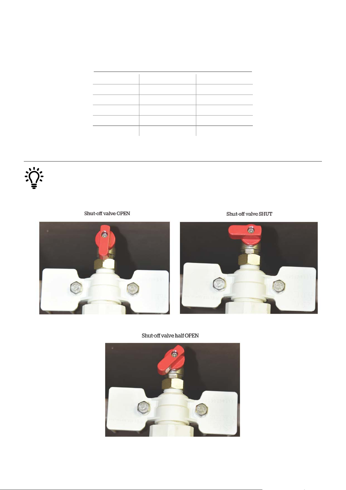
Using the shut-off valve as a pressure reducer
If high water pressure is an issue, the shut-off valve can be used to help reduce the flow of water into the valve. We
recommend the use of a pressure reducer in situations where water pressure exceeds 72.5 psi. (See
Pressure and
flow capacity
on page 13 if using a pressure valve).
14
Recommendations
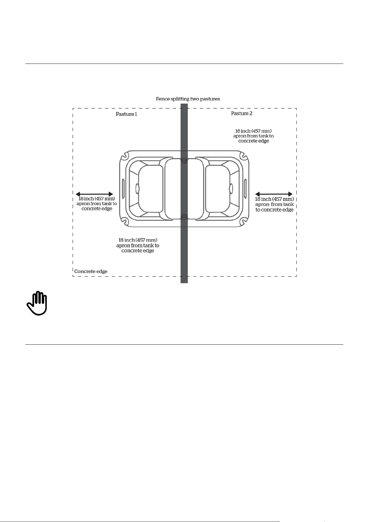
Split fence measurements
The WaterPro2 can also be used to split two pastures or pens with a fence line separating the drinking area. This allows
livestock from both sides of the fence to have access to water.
Check that you have enough clearance between the float reservoir lid and fence so that you can remove the lid to
get to the valve and float assembly.
General maintenance
If you are not using your WaterPro2 for extended periods of time, drain the tank and shut off the main water supply to the
tank.
Clean the tank weekly (at a minimum) to remove debris.
To facilitate easy cleaning:
•Use a stiff brush to clean the reservoir cavity.
•Remove the drain plug and flush.
•Turn the shut-off valve to the closed position or insert the drain plug into the hole in the float reservoir cavity.
•Repeat on the other side.
•The drain plug can be used to seal off one side of the tank if needed.

15
Troubleshooting
Symptom Possible cause/s Solution/s to check or action:
Water frozen in tank Water frozen in lines or
connections.
Vertical water supply line is properly insulated.
Tank bottom is sealed on concrete.
Livestock are drinking from the WaterPro2, if not, drain and refill
to recycle fresh water.
Vertical water supply line is centered within the thermal earth
tube.
Horizontal water supply line is 1 foot (51 mm) below the frost
line.
Low water flow Blockage or kinks in valves or
vertical water supply line.
Shut-off valve not set correctly.
Vertical water supply line is free from kinks.
Valve and float assembly has no blockages.
Shut-off valve is set to the open position. See the images of shut-
off valve positions in
Using the shut-off valve as a pressure
reducer
on page 13.
Check water pressure with a pressure gauge.
Water dripping out of
valve
Seals may need replacing. Check the valve diaphragm and seals.
Check that the valve connections have been tightened.
Valve and float assembly is clear of debris.
The shut-off valve is set to the open position. See the images of
shut-off valve positions in
Using the shut-off valve as a pressure
reducer
on page 13.
Valve does not shut
off
Worn diaphragm.
Replace valve and float assembly diaphragm.
Check pressure and flow capacity. See
Pressure and flow capacity
on page 13.
Drain plugs leak Worn drain plug or drain plug
screw not tightened.
Replace drain plug.
Tighten drain plug.
16
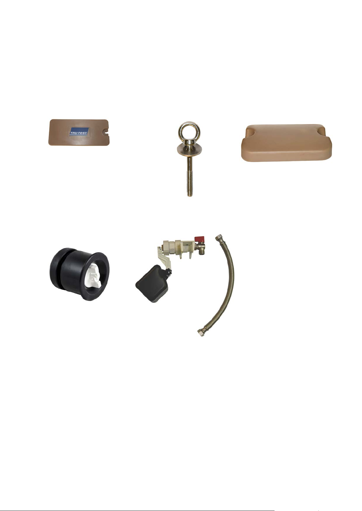
Spare parts
The parts below are available to order from your local Tru-Test WaterPro2 supplier.
Images are indicative of spare part and not shown to scale.
Panel door Spare panel door fastener kit Float reservoir lid
832895P
Excludes hardware and fastener kit
832894P
Eyebolt fastener and washer (2 pc)
832892P
Excludes eyebolt fasteners
Drain plug Valve and float
831839P
See overleaf for details of spare parts.
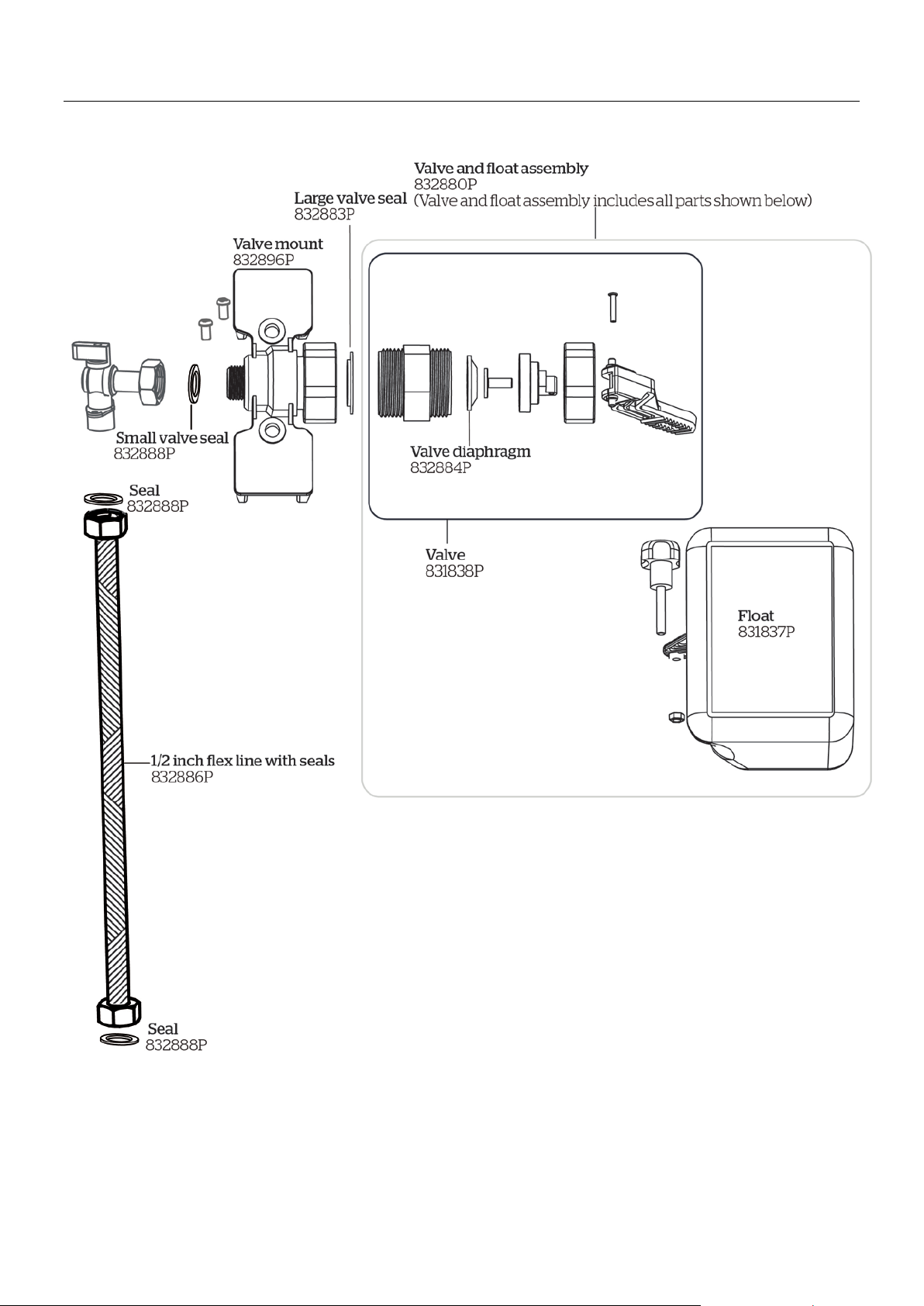
17
Valve and float

18
Product warranty
Terms and conditions for Livestock Automatic Watering products
Effective July 2017
Tru-Test, Inc.’s warranty obligations for Livestock Automatic Watering products manufactured by or for Tru-Test, Inc. are limited
to the terms set out in this policy.
Tru-Test, Inc. warrants its products to be free of defective materials and workmanship for the periods outlined below.
If a warranted defect occurs, please return the product along with proof of purchase to the place of purchase. If Tru-Test Inc.
receives a valid claim within the Warranty Period, Tru-Test Inc. will, at its option:
•Repair the product at no charge, using new replacement parts.
•Exchange the product with a product that is new or has functionality equivalent to the original product; or
•Refund the product’s original purchase price.
Warranty period.
The period of warranty (warranty period) begins at original date of purchase and runs for the following terms:
Base, Top and Float Reservoir Lid
•Eight years against manufacturing defect.
Component Parts (floats, valves, drain plugs, fasteners)
•One year against manufacturing defect.
Exclusions and limitations
This warranty applies only to genuine Tru-Test products manufactured by or for Tru-Test, Inc.
The liability of Tru-Test, Inc. under this warranty is excluded to the extent that any defect has been caused or contributed to by:
Any accident, contamination, tampering, modification, willful damage, improper storage, improper use or negligent act of, or
by omission by, any person other than Tru-Test, Inc.;
•Improper installation of the unit, or deterioration of the base upon which it rests;
•The use of the unit for any other purpose than providing a stationary source of water for livestock;
•The use of the unit for any other purpose than for which it was intended;
•The use of anything other than the original equipment or manufacturer’s parts;
•Any damage to the unit caused by storm, landslide, fire, lightning, earthquake, tornado or any other naturally occurring
phenomenon;
•Any damage to the unit caused by vermin or other pest, and any undermining of the base upon which the unit sits through
any cause whatsoever;
•This warranty specifically excludes the unit color, which may fade or change over time.
To the maximum extent permitted by law, this warranty is exclusive, personal to you, non-transferable, and in lieu of all other
warranties, representations or conditions relating to this product (whether express or implied and whenever arising) whether
originating by statute, law, trade, custom or otherwise.
The product warranty is only valid in the original country of purchase. Any claims made in another country may incur full repair
costs at the owner’s expense.

19
Advertencias de seguridad...................................................................................................................................................... 20
Registro de la garantía............................................................................................................................................................ 20
Antes de comenzar .................................................................................................................................................................20
Dimensiones del WaterPro2............................................................................................................................................ 20
Dimensiones de una losa de concreto básica.................................................................................................................. 20
Alineación del concreto con el agujero del tanque ......................................................................................................... 21
Instrucciones de desempacado ............................................................................................................................................... 21
Partes recomendadas...................................................................................................................................................... 21
Herramientas recomendadas........................................................................................................................................... 21
Partes incluidas ............................................................................................................................................................... 22
Instalación............................................................................................................................................................................... 23
Cortre transversal de la instalación final ......................................................................................................................... 23
Paso 1: Preparación del sitio........................................................................................................................................... 24
Paso 2: Instalación de las tuberías de suministro de agua.............................................................................................. 24
Paso 3: Instalación del suministro eléctrico para el cable del calentador de inmersión .................................................. 25
Paso 4: Instalación del tubo térmico subterráneo........................................................................................................... 25
Paso 5: Vertido de la losa de concreto............................................................................................................................ 25
Paso 6: Preparación de la tubería de suministro vertical de agua y verificación de fugas............................................... 26
Paso 7: Preparación del tanque ...................................................................................................................................... 28
Paso 8: Instalación del calentador de inmersión (opcional) ............................................................................................ 28
Paso 9: Llenado del tanque............................................................................................................................................. 28
Paso 10: Fijado del tanque a la losa de concreto............................................................................................................ 28
Capacidad de flujo y presión................................................................................................................................................... 29
Uso de la válvula de corte para reducir la presión .......................................................................................................... 29
Recomendaciones ................................................................................................................................................................... 30
Uso dividido por una cerca.............................................................................................................................................. 30
Mantenimiento general................................................................................................................................................... 30
Solución de problemas............................................................................................................................................................ 31
Piezas de repuesto.................................................................................................................................................................. 32
Válvula y flotador............................................................................................................................................................ 33
Garantía del producto............................................................................................................................................................. 34
Términos y condiciones para Productos de suministro de agua automáticos para animales de crianza ......................... 34

20
Debe leer cuidadosamente esta guía antes de instalar el WaterPro2.
¡Advertencia!
La instalación del WaterPro2 debe realizarse siguiendo cuidadosamente la normativa
nacional y local relativa a fontanería y artefactos eléctricos. Si la instalación o el mantenimiento de esta
unidad no se ejecuta según la normativa, podría sufrir lesiones personales, la muerte o la pérdida de
animales.
Envíenos sus datos para poder registrar su producto y mantenerlo informado de cualquier actualización importante. Más
información en livestock.tru-test.com/en-us/livestock-waterer-warranty-registration-form
Mida las dimensiones de la losa de concreto que necesitará.
Longitud x Ancho x Altura total
Longitud x Ancho x Altura total
WaterPro2
39,2 x 22,1 x 28,7 pulgadas
996 x 563 x 730 mm
Table of contents
Languages:
Other Tru-Test Farm Equipment manuals


Popular Farm Equipment manuals by other brands


USC
USC LP2000 Operator's manual

Pottinger
Pottinger NOVACAT V 10000 Original operating instructions

Farmet
Farmet DIGGER 3 N operating manual

Diesse
Diesse Trillo Use and maintenance handbook

Johnny's Selected Seeds
Johnny's Selected Seeds 9414 instruction manual

sitrex
sitrex DM/4 Spare Parts List and Assembly, Use And Maintenance


