SLC SG1D-1 User manual
Manual
300.000.123 I Version 02.2019
Progressive safety gear SG
braking downwards
Safety gear
SG1D-1

Progressive safety gear SG Manual
SG braking downwards
Published by
Sautter Lift Components GmbH
Remsstraße 2
70806 Kornwestheim I Germany
Phone: +49 (0) 7154.9996 - 0
Email: [email protected]m
Home: www.slc-liftco.com
Copyright © 2019 Sautter Lift Components GmbH
This manual is protected by copyright for the publisher and all rights are reserved.
This manual may not be reproduced in any way or copied by means of electronical copying methods, either as a whole or in
part, without written permission of the publisher. Translating the material also comes under the definition of copying.
Copyright as per DIN ISO 16016. Subject to modification.
www.slc
-liftco.com Doc. 300.000.123 I Version 02.2019 Page 2
Table of content
1. Safety instructions ...................................................................................................................... 3
1.1 Designations and signs ................................................................................................................ 3
1.2 Principle / intended use of the safety gear................................................................................... 3
1.3 Selection and qualification of personnel / basic responsibilities .................................................. 4
1.4 Safety instructions governing assembly and specific operational phases ................................... 4
2. General notes ............................................................................................................................... 5
2.1 Designation .................................................................................................................................. 5
2.2 Criteria for the selection of safety gears ...................................................................................... 5
2.3 EC type-examination certificate ................................................................................................... 5
2.4 Manufacturer of the safety gear ................................................................................................... 5
3. Technical Data ............................................................................................................................. 6
3.1 Range of application .................................................................................................................... 6
3.2 Tripping ........................................................................................................................................ 6
3.3 State of delivery ........................................................................................................................... 7
4. Mounting and dimensions .......................................................................................................... 8
5. Specification and function ....................................................................................................... 10
5.1 Specification of the safety gear .................................................................................................. 10
5.2 Function of the safety gear ........................................................................................................ 10
6. Assembly .................................................................................................................................... 11
6.1 Assembly of the safety gear at the lift car .................................................................................. 11
7. Commissioning .......................................................................................................................... 13
7.1 Functional check ........................................................................................................................ 13
7.2 Commissioning at the lift ............................................................................................................ 13
7.3 Acceptance test or commissioning of the lift.............................................................................. 13
7.4 Check after braking .................................................................................................................... 13
8. Content of QR-Code .................................................................................................................. 14
9. Maintenance ............................................................................................................................... 15
10. Transport .................................................................................................................................... 15
11. Annexe ........................................................................................................................................ 15

Progressive safety gear SG Manual
SG braking downwards Safety instructions
www.slc
-liftco.com Doc. 300.000.123 I Version 02.2019 Page 3
1. Safety instructions
This product information refers to the progressive safety gear type SG1D-1 braking downwards and
contains important information on correct and safe installation, putting into service, use and
maintenance of the safety gear. Observing these instructions helps to avoid danger, to reduce repair
costs and downtimes and to increase the reliability and life of the safety gear.
The product information has to be supplemented by instructions based on national rules and
regulations concerning accident prevention.
The product information must always be available wherever the safety gear is in use. The manual
must be read and applied by any person in charge of carrying out work with and on the safety gear.
In addition to the product information and to the mandatory rules and regulations for accident
prevention in the country and place of use of the safety gear the generally recognized technical rules
for safe and proper working must also be observed.
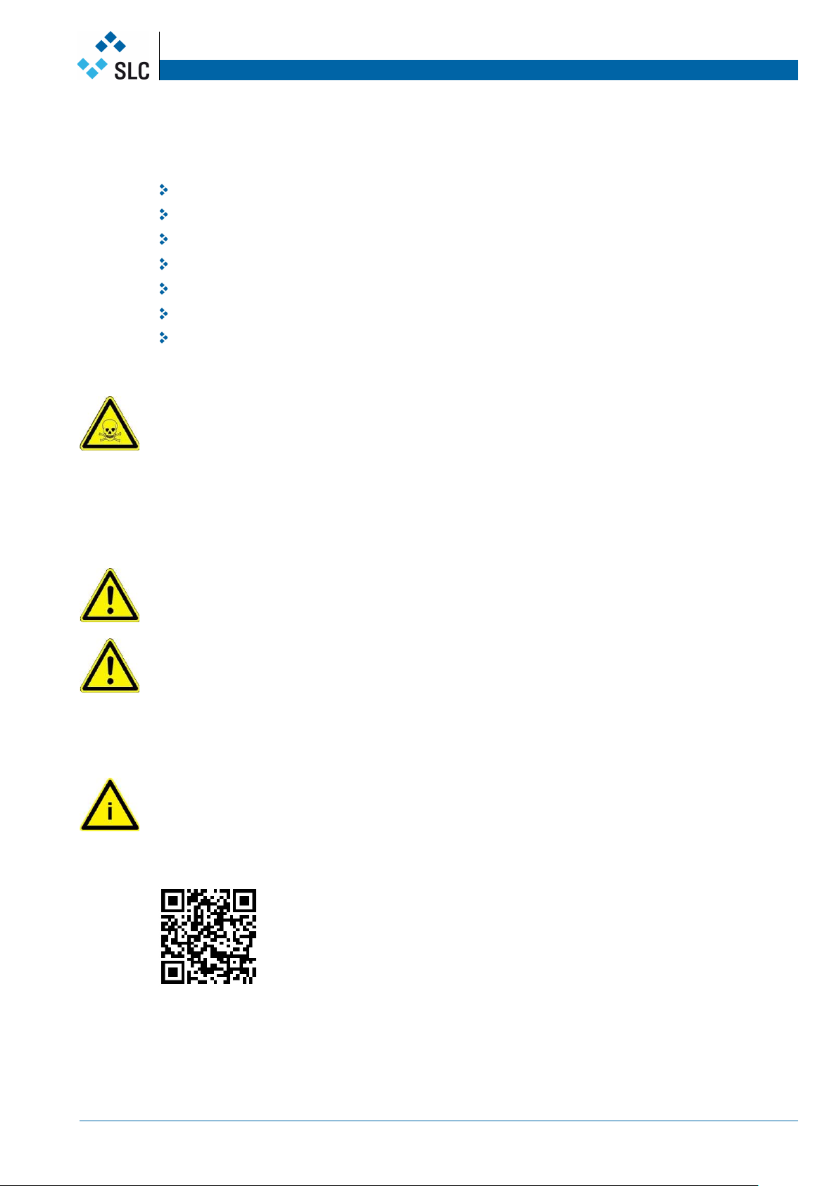
1.1 Designations and signs
The following designations and signs are used in this product information to designate instructions of
particular importance:
DANGER
In this manual refers to the risk of death, heavy injuries and extensive damage if the required
prevention measures are not taken.
WARNING
In this manual refers to light injuries or damage if the required prevention measures are not taken.
IMPORTANT
In this manual refers to important information about the product or is meant to attract the readers’
attention to important parts of the product information.
1.2 Principle / intended use of the safety gear
The safety gear has been built in accordance with current standards and the recognized safety rules.
Nevertheless, its use may constitute a risk to life and limb of the user or cause damage to the safety
gear and to other material property.
The safety gear must be operated in technically perfect condition only, in accordance with its
intended use and with the instructions set out in this product information.
Any functional disorders, especially those affecting the safety of the safety gear should therefore be
rectified immediately!
The safety gear SG braking downwards is designed exclusively for preventing the fall of the lift car
(see EN81-20:2014-11, chapter 5:6:2:1 and EN81-1/2:1998 +A3: 2009, chapter 9.8)
Using the safety gear for purposes other than those mentioned above is considered contrary to its
designated use. The manufacturer cannot be held liable for any damage resulting from such use.
The risk of any misuse lies entirely with the user.
Operating the safety gear within the limits of its designated use also involves observing the
instructions set out in this manual and complying with the inspection and maintenance directives.

Progressive safety gear SG Manual
SG braking downwards Safety instructions
www.slc
-liftco.com Doc. 300.000.123 I Version 02.2019 Page 4
Never make any modifications, additions or conversions that might affect safety without the supplier’s
approval!
Spare parts must comply with the technical requirements specified by the manufacturer. Spare parts
from original equipment manufacturers can be relied to do so.
Adhere to prescribed intervals for routine checks and inspections!
For the execution of maintenance work tools and workshop equipment adapted to the task on hand
are absolutely indispensable.
1.3 Selection and qualification of personnel / basic responsibilities
Any work on and with the safety gear must be executed by reliable personnel only. Statutory
minimum age limits must be observed!
Employ only trained and instructed staff and set out clearly the individual responsibilities of the
personnel for operation, set-up, maintenance and repair!
Make sure that only authorized personnel works on or with the safety gear!
1.4 Safety instructions governing assembly and specific operational phases
Assembly Always wear personal protective equipment during assembly work.
Standard
Operation Avoid any operational mode that might be prejudicial to safety!
Take the necessary precautions to ensure that the safety gear is used only when in a safe and
reliable state!
Main-
tenance Ensure that the maintenance area is adequately secured!
For carrying out overhead assembly work always use specially designed or otherwise safety-
oriented ladders and working platforms. Wear a safety harness when carrying out maintenance
work at greater heights!
Before cleaning with water or detergents cover or tape up all openings which - for safety and
functional reasons - must be protected against water or detergent penetration.
After cleaning remove all covers and tapes applied for that purpose!
Always tighten any screwed connections that have been loosened during maintenance and repair!
Ensure that all consumables and replaced parts are disposed safely and with minimum
environmental impact!
Gas
Dust
Steam
Smoke
Carry out welding or grinding work on the safety gear only if this has been expressly authorized, as
there may be a risk of explosion and fire!
Before carrying out welding or grinding operation, clean the safety gear and its surroundings from
dust and other inflammable substances and make sure that the premises are adequately ventilated
(risk of explosion)! When there is little space for working observe the national rules and regulations!
Oil
Grease
etc.
When handling oil, grease and other chemical substances, observe the product-related safety
regulations!
Be careful when handling hot consumables (risk of burning or scalding)!
Progressive safety gear SG Manual
SG braking downwards General notes
www.slc
-liftco.com Doc. 300.000.123 I Version 02.2019 Page 5
2. General notes
2.1 Designation
SG.. - . Safety Gear
1D braking in 1 Direction
2D braking in 2 Directions (see manual 300.000.155)
- 1 Type 1
Example SG1D-1 = Safety gear SG braking downwards, type 1
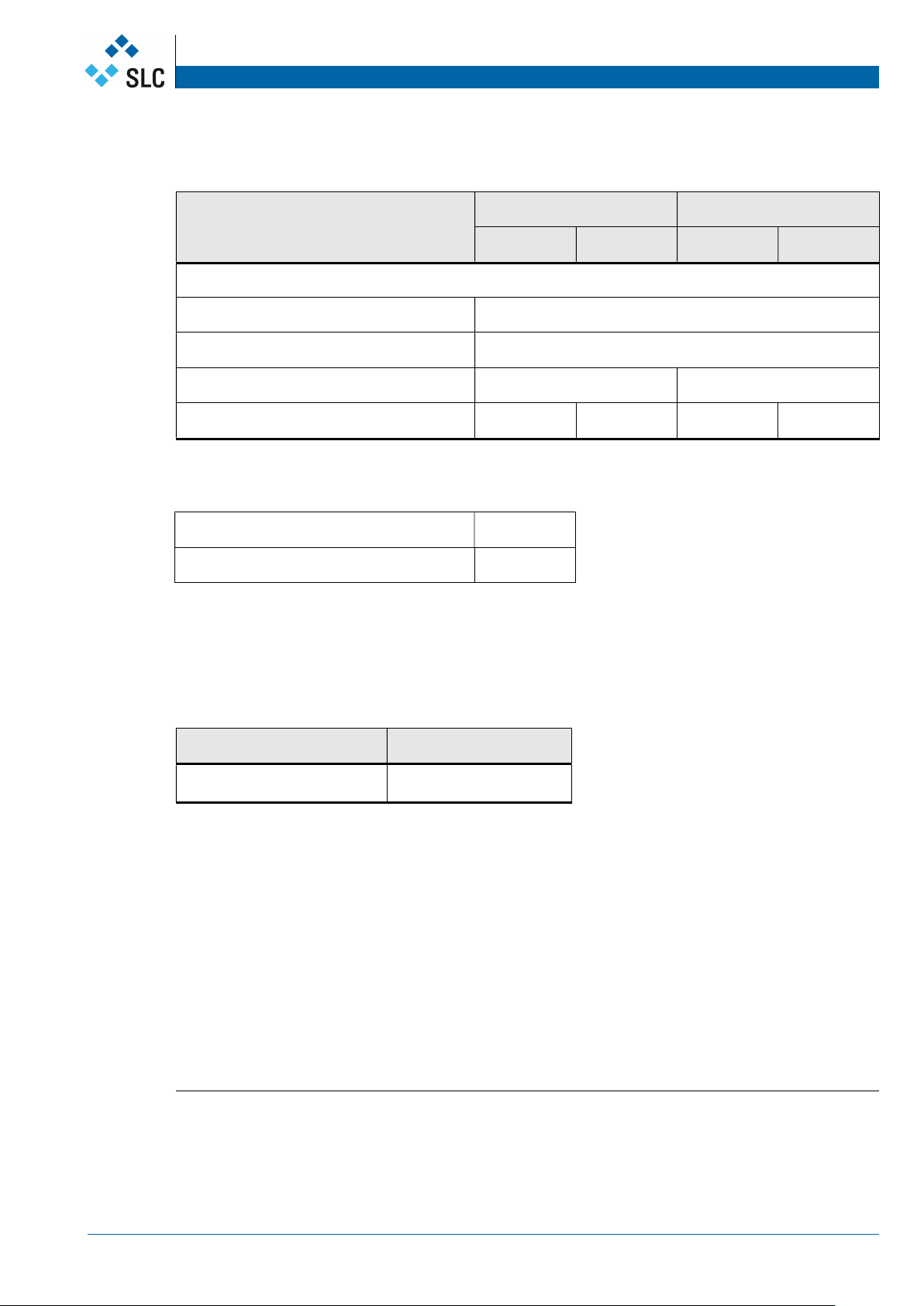
2.2 Criteria for the selection of safety gears
Rail head width
Load of safety operation P+Q
Counterweight mass
Car speed
Guide rail machined dry
oiled
drawn dry
oiled
2.3 EC type-examination certificate
Certification number of the EC type-examination certificate:
Type Certification no.
SG1D-1 EC-SG 802/1
Please note:
Type-examination certificates according to 95/16/EC
can be downloaded at SLC homepage:
http://www.slc-liftco.com/en/12/downloads.html
2.4 Manufacturer of the safety gear
Manufacturer of the safety gear and holder of the type-examination certificate:
Sautter Lift Components GmbH
Remsstraße 26
70806 Kornwestheim I Germany
Progressive safety gear SG Manual
SG braking downwards Technical data
www.slc
-liftco.com Doc. 300.000.123 I Version 02.2019 Page 6
3. Technical Data
Range of application
Machined rails Drawn rails
dry oiled1 dry oiled1
SG1D-1
Min. width of running surface 19 mm
Rail head width 5 – 16 mm
Max. rated speed [m/s] 3.23 3.23
Total mass min.-max. [kg] 543 – 3’095 523 – 2’935 305 – 2’605 299 – 2’547
Maximum tripping speed of the overspeed governor and range of maximum rated speed:
Max. tripping speed [m/s] 3.23
Max. rated speed [m/s] 2.50 – 2.80
3.1 Tripping
Below the minimum tripping force (without tripping device) required to trip the safety gear
Type Braking downwards
SG1D-1 120 N
The maximum admissible tripping force required at the safety gear shall not exceed 1600 N.
The individually needed tripping force has to be ascertained at the lift, considering all components.
Standard EN81-20:2014-11 rules that for the tripping of safety gears twice the required tripping
force has to be available – at least 300 N!
1
the indications for oiled guide rail refer to use of mineral oils without additive
(for example lubricant C according to DIN 51517, Part 1).
Progressive safety gear SG Manual
SG braking downwards Technical data
www.slc
-liftco.com Doc. 300.000.123 I Version 02.2019 Page 7
3.2 State of delivery
The safety gear is adjusted in the factory to the following lift specific characteristics:
Mass of lift car (P)
Mass of payload (Q)
Mass of compensation ropes
Rated speed of the lift car
Rail head width (5 – 16 mm)
Manufacturing mode of rails (machined, drawn)
Surface condition of rails (dry, oiled)
The setting is secured against alterations by the manufacturer by means of a seal.
DANGER
Wrong setting of the safety gear can result in falling-down of the lift.
The safety gear is adjusted by the manufacturer. As the deceleration depends on different, partially
lift-specific factors (material of guide rail, surface hardness of the rail, …) a precise pre-adjustment
cannot be guaranteed.
If a setting correction is exceptionally required, the setting has to be carried out only by specially
trained personnel after consultation with the manufacturer. The new setting has to be secured
against unauthorized alterations by means of a seal.
WARNING
The manufacturer cannot be held liable for damages caused by unauthorized setting alterations.
ACHTUNG
WARNING
Before installing the safety gear on the lift car its type plate characteristics have to be compared with
the lift characteristics. The type plate is mounted on the safety gear.
The safety gear must only be applied within the permission scope of application: see EC type-
examination certificate “Scope of application”, certificate no. see chapter 2.3.
IMPORTANT
The safety gear is set at work according to values specified in the order form for safety gears to
obtain the required braking force.
The order form can be downloaded on the homepage of SLC
http://www.slc-liftco.com/en/12/downloads.html
Progressive safety gear SG Manual
SG braking downwards Mounting and dimensions
www.slc
-liftco.com Doc. 300.000.123 I Version 02.2019 Page 8
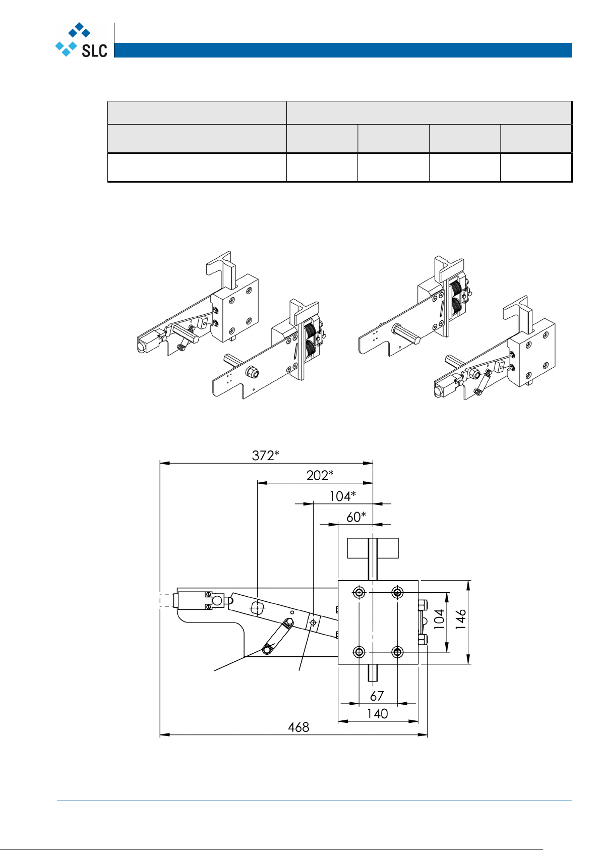
4. Mounting and dimensions
Installation dimensions
Type Weight
(Pair) Height Width Depth
SG1D-1 18 kg 144 mm 417 mm 55 mm
SG1D-1
* When brake is activated, the measure increases by approximately 5 mm.
Trigging of the
release force
Resetting
spring

Progressive safety gear SG Manual
SG braking downwards Mounting and dimensions
www.slc
-liftco.com Doc. 300.000.123 I Version 02.2019 Page 9
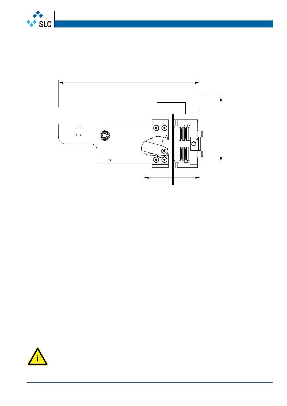
SG1D-1 with mounting brackets
Safety contact
Neutr
al
position
Progressive safety gear SG Manual
SG braking downwards Description and function
www.slc
-liftco.com Doc. 300.000.123 I Version 02.2019 Page 10
5. Specification and function
5.1 Specification of the safety gear
safety gear roller
roller guide
lever
brake shoe
rail
disk spring
distance plates
safety plate
internal housing
fishplate
5.2 Function of the safety gear
Upon tripping the overspeed governor both levers synchronised by the actuating shaft are turned
by 15°.
In doing so the safety gear roller moved by the lever makes contact with the rail surface.
The safety gear roller is pressed into the wedge-shaped gap between rail and roller guide . Owing
to the wedge effect of the roller guide the full floating beared safety gear is moved until the brake
shoe rests against the rail .
The disc spring transmits the braking force to the internal housing. To adapt to different widths of
guide blades distance plates of various thickness are placed under the disc.
The spring pressure is preset and secured by a safety plate and a led-sealing to prevent
unauthorized adjustment.
In the braking process the brake shoe fixed on the bracket cuts into the rail surface. The braking
effect is caused by metal cutting in the rail surface, friction and spring tensioning work.
Moving the lift car upwards releases the brakes and lever and the safety gear rollers return to neutral
position.
The safety gear is ready for action again.
IMPORTANT
The safety gear transmits the braking force to the car. This braking force must be taken into account
in the construction of the interface between safety gear and car.
139
144
420

Progressive safety gear SG Manual
SG braking downwards Assembly
www.slc
-liftco.com Doc. 300.000.123 I Version 02.2019 Page 11
6. Assembly
6.1 Assembly of the safety gear at the lift car
The safety gear is fixed to the lift car with four screws of type M12 and bushes.
Pay attention to the full floating bearing the safety gear as this is the key to the safety gear sliding
into braking position after being tripped by the overspeed governor.
WARNING
When the safety gear is in neutral position it can be adjusted using the adjustment mechanism.
The following points must be observed:
The rail running guide must cover the brake shoes completely. The air gap between the rail running
surface and the brake shoe must be adjusted to 2 mm.
The safety gear must be installed so that the spring mounted brake shoe is parallel to the rail and in
direction of travel.
width of rail
5-16 mm
Setting of elastic
force secured with
seal
air gap 2 mm
Washer with variable
thickness for adjusting
various widths of rail blades
Progressive safety gear SG Manual
SG braking downwards Assembly
www.slc
-liftco.com Doc. 300.000.123 I Version 02.2019 Page 12
WARNING
Ensure that the mounting screws in the long slots of the external housing have enough play in both
directions in neutral positions.
Correct position of the safety gear
During assembly the safety gear on the car take care for the correct position of the safety gear.
Firstly there is an advice on the type plate of the safety gear, secondly the following characteristics of
the safety gear roller is only given if the safety gear is mounted correctly:
By pulling the lever upwards the gap between safety gear roller and rail gets smaller until the safety
gear roller rests against the rail.
WARNING
Incorrect installation of the braking device causes a functional disorder of the safety gear.
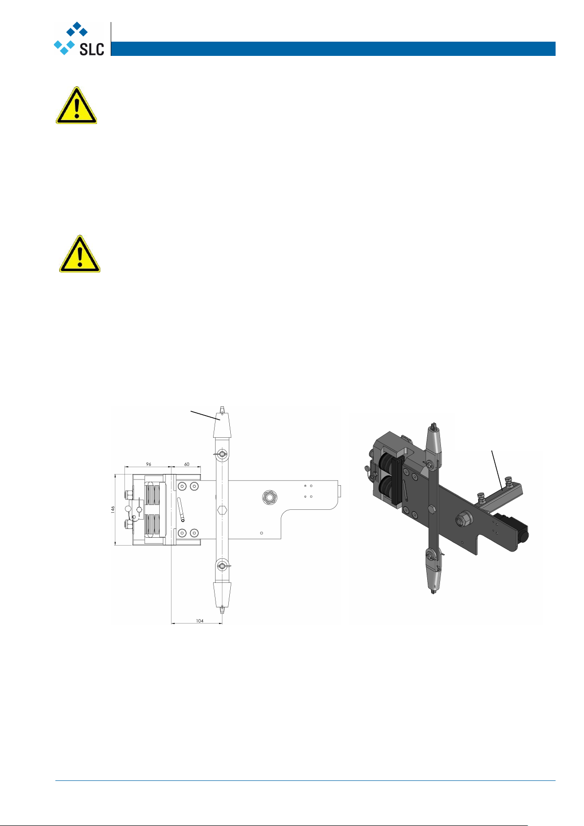
Linkage of the braking units
Both safety gear units are linked with an actuating shaft.
The actuating shaft is fixed to the lever of the safety gear with attachment screws or spring type
straight pins. The actuating shaft is connected by mean of two square-type tubes 20x20 mm.
Coupling to connect with
other safety housing
through linkage tube
Linked to OSG-rope
(Overspeed governor)

Progressive safety gear SG Manual
SG braking downwards Commissioning
www.slc
-liftco.com Doc. 300.000.123 I Version 02.2019 Page 13
7. Commissioning
7.1 Functional check
WARNING
Before commissioning the safety gear
make sure that the overspeed governor works correctly, that the safety gear is attached to the
overspeed governor and that the produced tractive force is two times the force required for
engaging the safety gear.
the guide rail must be cleaned of dirt. Most suitable for cleaning is cold solvent.
Before commissioning the lift car
the lift car must be braked statically:
by turning the actuating shaft until both safety gear rollers contact the guide rail as well as letting
the car down slowly. It has to be checked if both safety gear rollers move to their working
position.
the lift car must be braked with low speed.
It has to be checked if both safety gear rollers move to their working position.
For checking the braking force it is possible to trip the safety gear with rated speed or overspeed.
By pulling out from braking position the lever of the safety gear roller turns back into neutral position.
WARNING
The safety gear may be operated only in combination with an overspeed governor.
7.2 Commissioning at the lift
Braking the car in down direction with 125% of payload decelerations of the car must be between
0,2g and 1g (9,81m/s2).
7.3 Acceptance test or commissioning of the lift
IMPORTANT
Engagement test downwards
Tests before commissioning the lift according to EN81-20:2014-11, chapter 6.3
(EN81-1/2:1998+A3:2009, Annexe D) resp. periodic tests according to EN81-20:2014-11, Annexe C
(EN81-1/2:1998+A3:2009, Annexe E).
7.4 Check after braking
After every braking the safety gear has to be rechecked by a qualified person.
There is to be checked visually whether any changes or dirtying at the braking elements has
occurred.
The following points have to be rechecked:
excessive wear of the brake shoes
deformations
smooth running
The rubbed-off particles have to be removed and the braking marks grinded down.
Braking again on a re-grinded braking track is not causing an essential change of the braking force.
DANGER
For guide rail lubrication oil products approved in the type examination certificate shall be used only.
Use machine oil of viscosity class ISO 68-150 without extreme pressure additive. See mineral oils
without additive (for example lubricant C according to DIN 51517, Part 1.)
Oils for hydraulic aggregates, gears and motors are not suitable for this use.
Progressive safety gear SG Manual
SG braking downwards QR-Code
www.slc
-liftco.com Doc. 300.000.123 I Version 02.2019 Page 14
8. Content of QR-Code
Description Data field Type Length
(symbol)
Safety components from other
suppliers
1 Product name CHAR 40 Product name of safety gear
2 Release NUM 2
3 Revision NUM 2
4 Identification number CHAR 35 SL product number
5 Serial number CHAR 18
6 Batch number CHAR 10 Only when serial number is not
available
7 Manufacturer name CHAR 30 Name of manufacturer
8 Manufacturer postal
code
CHAR 10 Postal code of manufacturer
9 Manufacturer town CHAR 30 Town of manufacturer
10 Manufacturer
country code
CHAR 5 Two-character country code
according to ISO 3166-1
11 Importer name CHAR 30 Name of importer
12 Importer postal code CHAR 10 Postal code of importer
13 Importer town CHAR 30 Town of importer
14 Importer country code CHAR 5 Two-character country code
according to ISO 3166-1
Notice: Data fields without values are marked with "---". If numbers 2 and 3 (approval and
revision) are not necessary, fields remain empty.
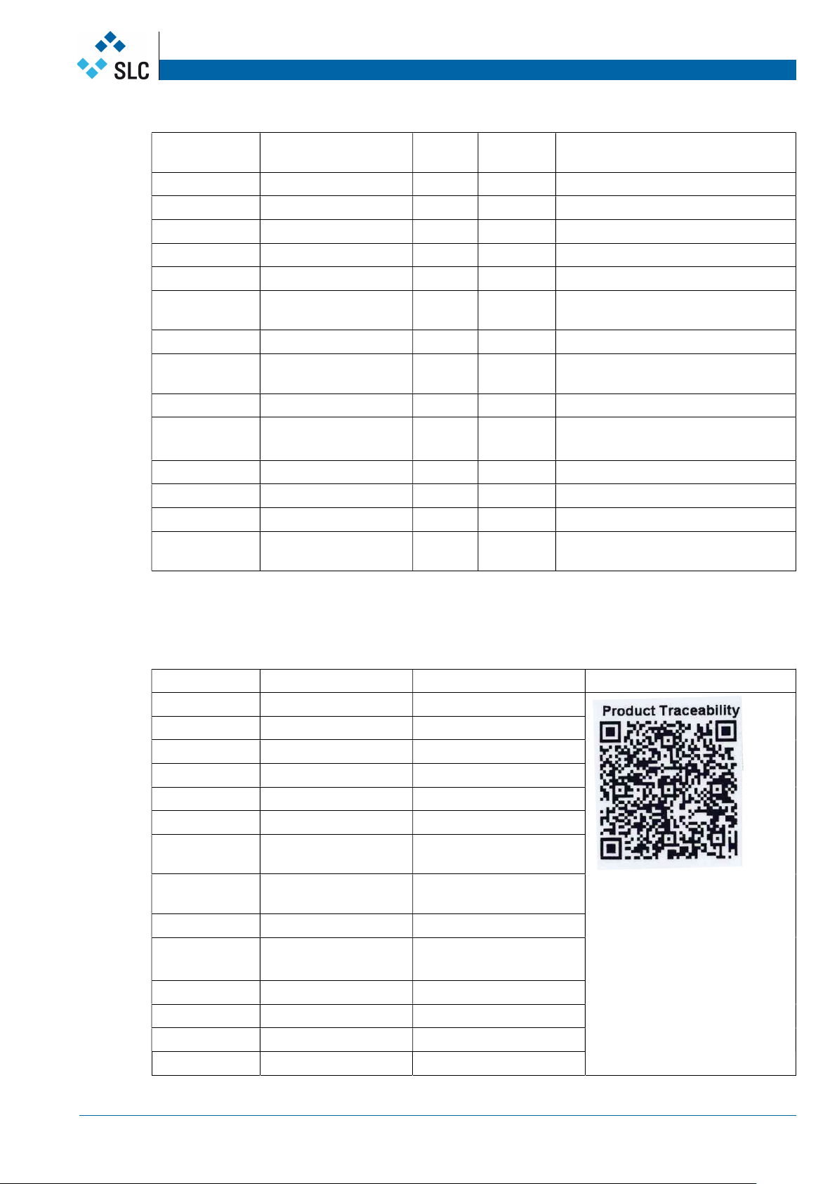
Example of QR-code for SG1D-1 safety gear from SLC:
Description Data field Text in QR-code Sample QR-code
1 Product name SG1D-1
2 Release
3 Revision
4 Identification number 50100505
5 Serial number 16/5821
6 Batch number ---
7 Manufacturer name Sautter Lift Components
GmbH
8 Manufacturer postal
code
70806
9 Manufacturer town Kornwestheim
10 Manufacturer
country code
DE
11 Importer name SLS Sassi Lift Systems
12 Importer postal code CM7 2QJ
13 Importer town Braintree
14 Importer country code GB
Progressive safety gear SG Manual
SG braking downwards Maintenance and transport
www.slc
-liftco.com Doc. 300.000.123 I Version 02.2019 Page 15
9. Maintenance
Upon maintenance the safety gear shall be checked for:
smooth operation
synchronous operation of the two units
wear
rust
dirt
sealing
If, after a couple of braking tests, the braking rollers or the safety gear base show signs of wear they
are to be replaced by qualified persons.
Material numbers:
Brake shoe 106.930.288
Safety gear roller 106.920.120
Roller guide 106.700.191
10. Transport
Any work upon transport, storage, installation and commissioning as well as (if any) demounting and
disposal of a safety gear is to be carried out by qualified persons only.
They shall be responsible for proper assembly, transport and installation, and for putting the safety
gear into operational condition. If this is not ensured, the manufacturer shall not be held liable for any
damages that might occur.
Upon transport the safety gear must be protected against:
humidity
shock
dirt
falling-down, etc.
11. Annexe
EU type-examination certificate EU-SG 802
Certificate of conformity
IMPORTANT
Find more certificates of conformity in additional languages on our homepage:
http://www.slc-liftco.com/en12/downloads.html.
Table of contents
Other SLC Industrial Equipment manuals


