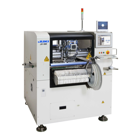
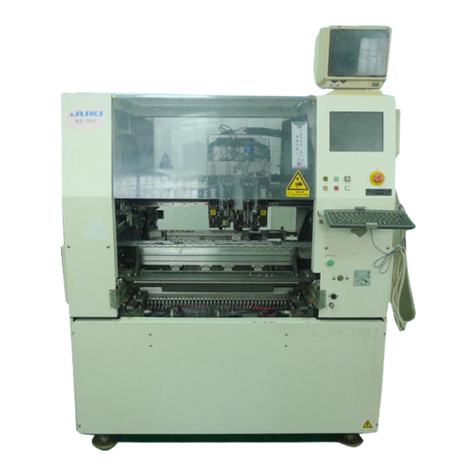
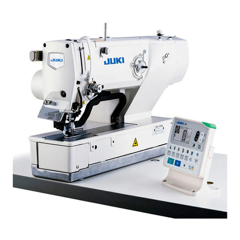
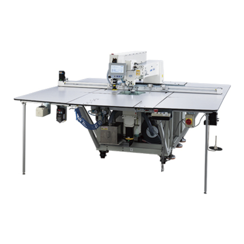
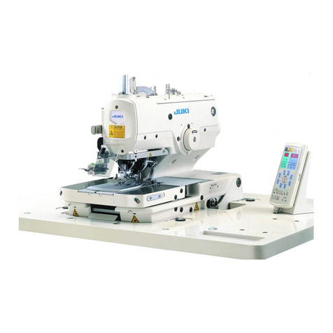
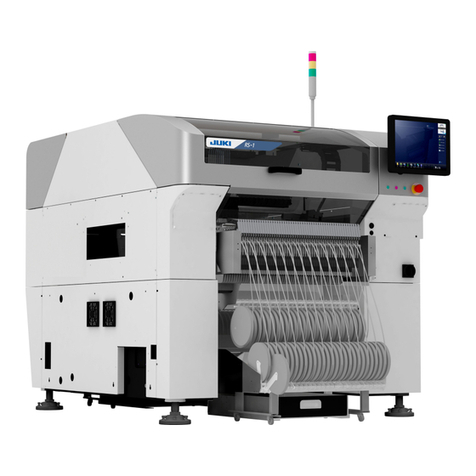
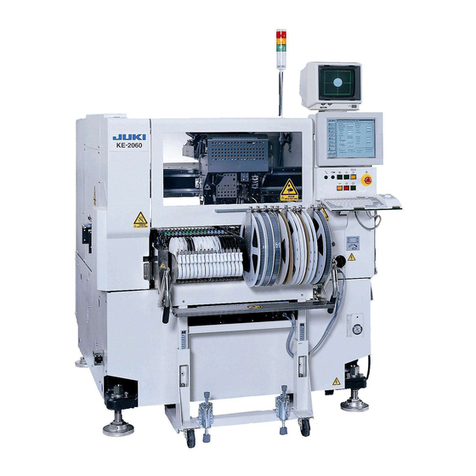
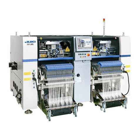
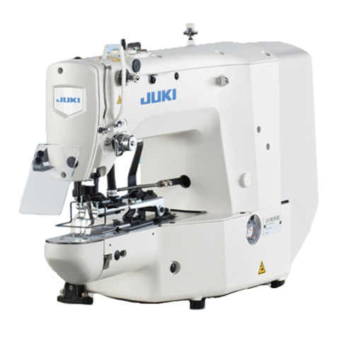
JUKI 72005824 User manual

咨询:
JUKI CORPORATION Customer Business Company
E-mail: [email protected]
系列名称 Bartacking Machine
型号(产品)名称 LK-1900A/ LK-1900AN/ LK-1900B/ LK-1900BN 发行 No. A18P-039
发行源 JUKI CORPORATION Customer Business Company 发行日 2018/0/6
编号新增设
编号取代
编号废除
其他
钉扣机小工具套装用文挡
【对应机种】
LK-1900A/ LK-1900AN/ LK-1900B/ LK-1900BN
【内容】
关于 LK1900 用的钉扣机小工具套装,将刊登以下的文档,请您使用。
・使用说明书 P.2~18
・零件样本 P.19~23

Button sewing clamp kit
(Vertical button attach device)
Instruction Manual
72005824(for LK-1900A/AN/B/BN)
Rev.001
2018.06.08

Contents
Contents ................................................................................................................... 1
I. Precautions before operation .......................................................................................... 2
II. Name of main unit ............................................................................................. 2
1. Name of component ............................................................................................. 2
2. Standard accessories ................................................................................................ 3
Specifications ....................................................................................................... 4
IV. Installation ................................................................................................ 5
1. Removal of the needle .......................................................................................... 5
2. Removal of the feed bracket ................................................................................. 5
3. Removal of the work clamp foot ....................................................................................... 6
4. Mount the button sewing device on the feed bracket ............................................................ 6
5. Replacement of the needle guide .................................................................................... 7
6. Replacement of the feed plate .......................................................................................... 7
7. Install a feed bracket (with button sewing device) on the arm bed ............................ 7
8. Attach a needle .......................................................................................... 8
9. Replacement of lengthwise feed sensor slit .................................................................. 8
10. Origin Sensor Adjustment .................................................................................... 9
10.1 LK1900A/AN ........................................................................... 9
10.2 LK1900B .............................................................................. 11
V. Operation ....................................................................................................... 12
1. Preparation before Operation ....................................................................................... 12
1.1 Mount the button rising bar ........................................................................ 12
1.2 Changing the type of machine ....................................................................................... 12
1.3 Standard Pattern List ........................................................................... 14
2. Sewing procedure ....................................................................................... 15
VI. Maintenance ......................................................................................................... 16
1. Grease coating
.......................................................................................... 16
1Page

I. Precautions before operation
For safety precautions, pay attention to the following precautions before running
・When the power is turned on, there is a possibility that the buttoning device may operate,
Do not place hands or objects under or in the vicinity of the device.
・When removing or installing parts, follow "IV. Installation."
II. Name of main unit
1. Name of a component
Vertical button attached device
❶Machine head
❷Work clamp foot
❸Thread stand
❹Operation panel
❺Switch box
❻Control box
❼
Pedal
2Page

2. Standard accessories
Check the packaged parts before installation.
Product no.:72005824
No. Qty
1 1
2 1*
3 1*
4 1*
5 1*
6 1*
7 1*
8 1*
9 1*
10 1*
11 1*
12 1*
WP0370316SD
SPRING_LEFT_B (THIN BUTTON)
SPRING_RIGHT_B (THIN BUTTON)
SS6080340SP
72005822
72005821
72005816
Parts Number
72002988
72002987
MAZ15601000
72003011
40205494
40021011
Parts name
PLAIN_WASHER
SCREW
SPRING_LEFT_C (THIN LARGE BUTTON)
SPRING_RIGHT_C (THIN LARGE BUTTON)
LENGTHWISE_FEED_SENSOR_SLIT
FEED_PLATE_A
VERTICAL_BUTTON_ATTACH_DEVICE
BUTTON_RISING_BAR
GUIDE
SMALL GAUGE
72005817
*Accessory_parts_components:40205495
4
3
2
6
7
8
1
5
910 11 12
3Page

Ⅲ.Specifications
●Model name Vertical button attached device
●Applicable model LK-1900A
LK-1900AN
LK-1900B
●Sewing speed Maximum 2700sti per minute
●Sewing area 4.5mm in length × 4.5mm in width (buttonhole spacing)
●Device dimension W:55 mm、L:88 mm、H:70 mm
●Needle used DPx17(#14)
●Lift of the work clamp Maximal 12 mm
●Button size Outer diameter: φ8 to φ 21 mm
Thickness :1~4.5 mm
Button hole spacing 0-4.5 mm
1~4.5mm
φ8~φ21mm
4Page

IV. Installation
1. Removing the needle
2. Removal of the feed bracket
1) Remove the set screw❷to remove the
needle❶
1) Remove the feed bracket❶by loosening
the screw❷and the washer❸
●CAUTION: To prevent accidents due to inadvertent activation, be sure to switch off the power before starting.
❶
❷
❶
❷
❸
〇NOTE: Be careful not to generate a ball because
the metal ball is on top of the feed barrel.
5Page

3.Removal of the work clamp kit
4. Mount the button attached device on the feed bracket
1) Put the button attached device❹in the feed
bracket❶, attach two lifting levers❸, tighten two
collar ⓭and four screws❺, and then apply two
springs❷
1) Secure the feed bracket❶, remove the two
springs❷, loosen the four screws❺, remove the
two lifting levers❸, and remove the two working
feet❹.
❶
❷
❸
❹
❺
❷
❸
❶
❺
❹
❽
❼
❻
❾
⓫
⓬
A
B
❿
○CAUTION: When the device❹cannot be
smoothly inserted into the feed bracket❶
remove the spring❻, remove the set screw❼
and
two screws❽, and remove the lever assembly❿
without removing the screw❾.
Then, loosen the two screws⓫and the two
screws⓬, place the device❹in the feed
bracket❶, and tighten the two screws⓫and the
two screws⓬so that the A and B sides are in the
same plane.
Then, attach a lever assembly❿with two
screws❽and a set screw❼, and then apply a
spring❻.
6Page

5. Replacement of the needle guide
6. Replacement of the feed plate
7. Attach a feed bracket (with a button attached device) to the arm bed.
1)Loosen the two screws❷, remove the current
needle guide, install the accessory needle guide❶
and tighten the two dishes screws❷.
1) Remove the screw❷to remove the current feed
plate and attach the accessory feed plate❶. Then
tighten the screw❷.
1) Attach the feed bracket❶(with device) to the
arm bed and tighten the washer❸and screw❷
Needle gide for
accessories
❷
❶
❶
❷
Feed plate for
accessories
❶
❷
❸
7Page

8. Attach a needle
9. Replacement of lengthwise feed sensor slit
1)Loosen the two screws❷to remove the right
bed cover❶
2) Loosen the screw❸, remove the current feed
sensor slit, install the accessory sensor slit❹and
temporarily secure the screw❸.
1) Attach the needle❶with the set screw❷
❶
❷
❶
❷
❸
❹
〇Note: The screw❸is adjusted in the
center of the long slit hole and is
temporarily secured (be careful not to
interfere with the slit ❹and sensor ❻).
❹
❻
8Page

10. Origin Sensor Adjustment
・Turn on the power. Small gauge Small button
・Press the key.
・Put the accessory small gauge into the device.
(If there is no button gauge, a small button may be used.)
・Turn on the power supply.
・Turn it on again.
・Turn on the power and make the following adjustments.
10.1 For LK1900A /AN
1. Starting XY Motor/Origin Sensor Check Mode
・ Press the key twice.
・ Press the key to change
Select
・ Press the key.
・ Press the key.
・Press the key for 3 seconds while the
sewing LED disappears (the buzzer sounds).
●NOTE: Work with the power on. Never touch the switch other than necessary to prevention
accidents due to malfunction.
9Page

2. Origin Sensor Slit Adjustment
2 .1 Press the key to select the X-Y origin sensor.
※After adjustment, attach the right and left bedcovers.
2 .3 Adjust the X sensor slit❶and Y sensor slit ❹by loosening the screws ❷❺with the central
hole of the button gauge and the needle tip aligned. While adjusting the sensor slit, look at the display of
the panel and tighten screws ❷❺when the display value is "1" to "0" (please note that when
tightening, the sensor slit does not interfere with the sensor ❸❻).
2 .4 Press the key to check that the center hole of the button gauge is combined
with the tip of the needle when the display value of the panel is from 1 to 0 (check each X-Y origin
sensor). If not combined.readjust by 2 .1 - 2 . 4
2 .2 While pressing the key, check the coincidence between the central hole of the
button gauge and the needle tip.
The X/Y origin sensor status selected indicates
"0" or "1".
Keys to drive the selected X/Y
motors by 0.1 mm in a +
-direction.
X Displays the selection status of the motor (X origin sensor) or
Y motor (Y origin sensor).
Press the key to switch.
X Expanded reduction rate LED lights: X
-point-of-
origin sensor
Y Expanded reduction rate LED lights: Y Origin sensor
The key switches between the selected X
motor (X origin sensor) and Y motor (Y origin
sensor).
X-origin sensor
❶❷
❸
Y-origin sensor
❹❺
❻
10Page

10.2 LK1900B
1.Startup of XY Motor/Origin Sensor Check Mode "02 X/Y Motor Origin Adjustment"
2.Origin Sensor Slit Adjustment
・ Press the returning key ❾to return to the
Check Program screen.
※After the adjustment, tighten the screws❶and
install the bed carver.
・Press the Item Selection Key❻on the Check
Program screen, select 02 X/Y Motor Origin
Adjustment, and then press Edit Key ❽to use the
selected function.
・When the Preparation LED⓮is turned off
and the Mode key❹is pressed for 3 seconds, the
beeper will beep and the "13 Check Program" will
appear on the Mode screen.
・Press the Item Selection Key ❻to drive
the X motor by ±0.1 mm.
A This box indicates the X-ray motor encoder
position information.
Pressing the data change key ❼drives Y motor
by ±0.1 mm in increments.
B This box indicates the Y motor encoder
position information.
・Adjust the button gauge so that the center
hole and needle tip are aligned by changing the
selection key ❻and change key ❼.
・When the center hole of the button gauge is
aligned with the tip of the needle, press the
preparation key❷for 2 seconds to bring the
current position to the XY origin.
❶
●A typical button can
be used instead of a
button gauge.
At that time, adjust the
tip of the needle to the
center of the button.
Center of the Button
Needle
Needle
Center hole of the
button gauge
11Page

V. Operation
1. Preparation before Operation
1.1 Button float bar (optional)
1.2 Changing product type
※For LK1900A /AN
and mode Select.
・ Press the key.
・Press the key for 6 seconds while the
sewing LED has disappeared (in the service level
setting mode of the memory switch).
・ Press the key to register the changes.
・ Use the key to change the
memory switch from 0 to 7.
1) Use a button rising bar asm.❶to attach it like
an image.
・ Modify with key
12Page

※For LK1900B
・Press Mode Key❹for 6 seconds to display a
15 memory switch 2 on the Mode screen.
・Press the Item Selection Key ❻to select
"15 Memory Switch 2" and then press Edit Key
❽.
・Press the Item Selection Key ❻to select
K241 and change the settings to "7" with the Data
Change Key ❼.
15 Memory switch 2
13Page

1.3 Standard Pattern List
14Page

2. Sewing procedure
1. Check the power supply "off",
2. Select the button hold spring and replace.
3. Turn on the power,
4. Select the sewing pattern (refer to "V.1/1.3 Standard Pattern List"),
5. Put the button into the device to adjust the lever (see Image of Rever Adjustment),
6. Press the Preparation key,
7. Put the sewn button into the clamp foot to adjust,
8. The fabric is placed on the feed plate.
9. Push down when stepping on the pedal switch and rise when leaving it (two-stage pedal),
10. Sewing begins when the pedal is pushed into the second stage,
11. After the sewing is finished, the presser automatically rises and returns to the sewing start position.
・Repeat 7 to 10 for the sewing operation
・When changing the button specification, repeat 1.-10.
No
1
2
3
4
5
6
Lever Adjustment: Loosen the set screw❷, set
the sewing button, and adjust the clearance
between the lever❶and the screw❸to 0.5-1
mm as shown in the image. Then, tighten the
set screw❷.
Button thickness
Part Number
Replace the button hold spring: remove the
spring❹ and remove the two washers❻ and
the two screws❼ and replace the button hold
spring❺ and ❽. Then attach two washers❻
and two screws❼ and apply a spring❹.
※Please refer to the button hold spring chart
during replacement.
Note that when sewing small buttons, Nos.
3 and 4 may interfere with the needle. In
doing so, use No. 5 and No. 6.
Remarks
Button hold spring table
72005815
72005821
72005822
72005816
72005817
1~2.6mm
2.6~4.5mm
72005814
Replacement of button hold spring
❹
❺
❻
❼
❽
0.5~
Lever adjustment
❶
❸
❷
Two-stage pedal
15Page

VI. Maintenance
1. Grease coating
Coating
Coating
Coating
Coating(Thin coat)
Coating
Coating
・Grease IE22
・Apply a thin coat of grease.
16Page

ボタン付けクランプキット/Button sewing clamp kit
(垂直方式ボタン付け装置/Vertical button attach device)
(LK-1900A/AN/B/BN用/for LK-1900A/AN/B/BN)
PARTS LIST
Rev 001
2018.06.08
72005824

1. 垂直ボタン付け装置 ( 1 ) 40205494
1. VERTICAL BUTTON ATTACH ASM ( 1 ) 40205494
No. Qty
1つまみ足取付台 FOOT_INSTALLING_BASE 1
2スライド板 SLIDE_PLATE 1
3段ねじ SHOULDER_SCREW 1
4スライド板左 SLIDE_PLATE_LEFT 1
5スライド板右 SLIDE_PLATE_RIGHT 1
6サラコネジ SCREW 2
7サポート板 SUPPORT_PLATE 2
8ヒラネジ SCREW 2
9サラコネジ SCREW 2
10 サポート板右 SUPPORT_PLATE_RIGHT_A 1
11 ボタンガイド足 BUTTON_GUIDE_FOOT 1
12 マルヒラネジ SCREW 1
13 ボタンヒラキレバー トメネジ CLAMP SCREW A 1
14 つまみ足開きレバー CLAMP_RELEASE_LEVER 1
15 段ねじ SHOULDER_SCREW 1
16 段ねじ SHOULDER_SCREW 1
17 サラコネジ SCREW 4
18 サポート板左 SUPPORT_PLATE_LEFT 1
Part No.
パーツ名
40205494(1)
Parts name
72002990
72002994
SD0600208TP
72002992
72002991
SM1030501SC
72002993
SM6041050TP
SM1031001SC
72005742
72002995
SS7110510SP
B2549372R00
72002999
SD0500251SP
SD0600208TP
SM1030801SC
72002997
10
11
12
13
14
15
16
17
18
1
2
3
45
6
7
8
9
Table of contents
Other JUKI Industrial Equipment manuals
Popular Industrial Equipment manuals by other brands

SPX Cooling Technologies
SPX Cooling Technologies Marley Geareducer 2200 user manual

Crown
Crown DWT-20 Installation & operation manual

Siemens
Siemens MOBILETT Plus HP Maintenance Instruction

Digga
Digga TPE-000050 Operator's manual

TLV
TLV QuickTrap FJ32-X instruction manual

ALLU
ALLU D Series instruction manual