WPG MRPT89AC User manual

Rev 34.2/10-22 MRPT89AC: #350601
OPERATING
INSTRUCTIONS 908 W. Main • P.O. Box 368
Laurel, MT USA 59044
800-548-7341 (phone)
406-628-8231 (phone)
406-628-8354 (fax)
www.WPG.com
Record serial number in blank space above (to locate, see serial
label on the product).
MANUAL ROTATOR /
POWER TILTER 1000,
AC-VOLTAGE
Model number: MRPT89AC(O)
KEEP FOR FUTURE REFERENCE
INTENDED FOR USE BY SKILLED
PROFESSIONALS • READ AND
UNDERSTAND BEFORE OPERATING

MRPT89AC: #35060 Rev 34.2/11-222

Rev 34.2/11-22 MRPT89AC: #350601
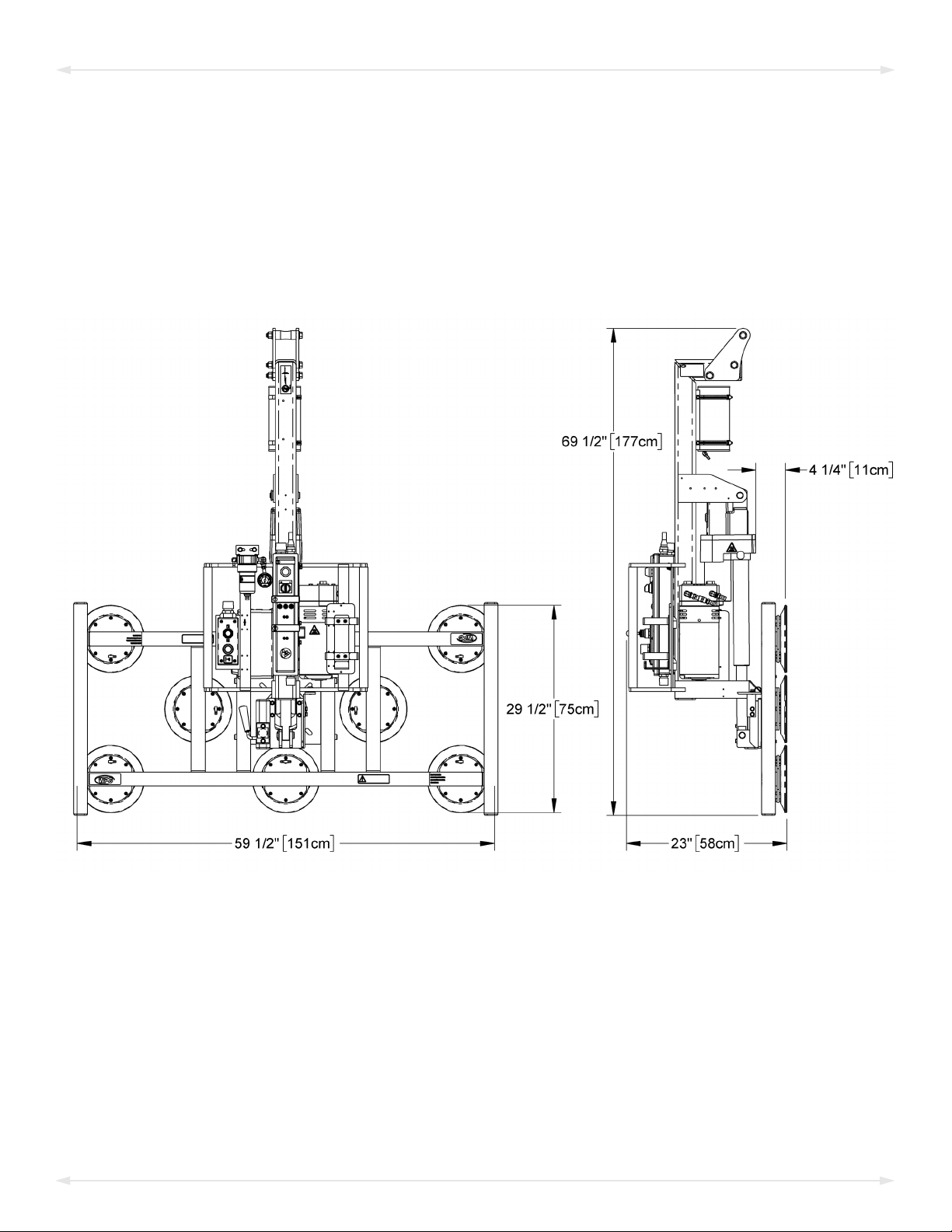
SPECIFICATIONS .....................................................................................3
SAFETY...................................................................................................5
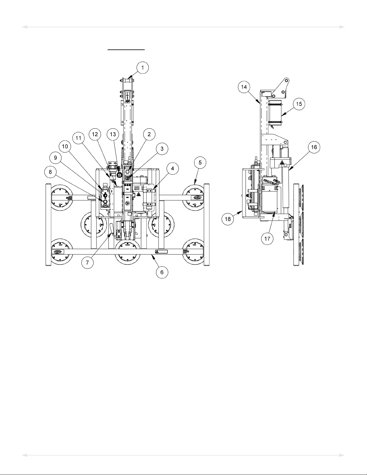
OPERATING FEATURES............................................................................6
ASSEMBLY..............................................................................................7
PAD FRAME OPTIONS .................................................................................10
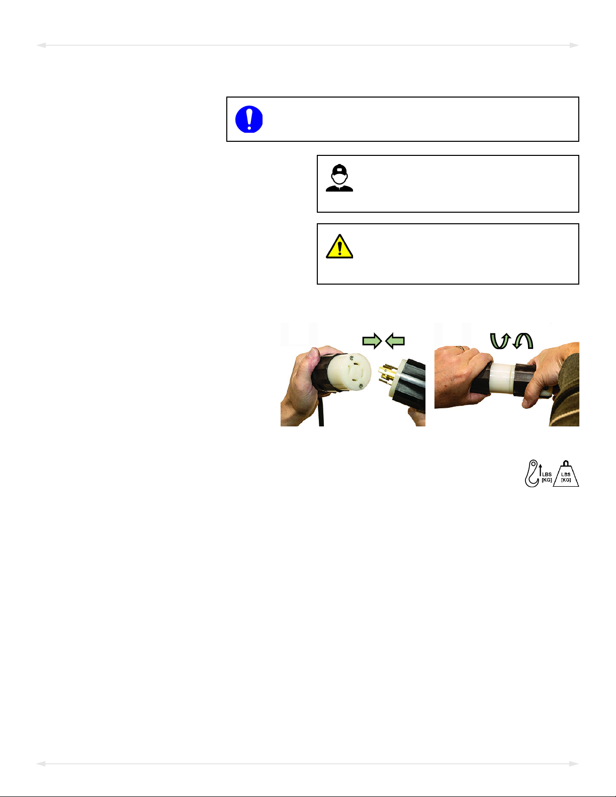
Connecting/Disconnecting Vacuum Hoses .......................................................................11
Repositioning the Optional Telescoping Pad Arms ...........................................................11
Removing the Optional Telescoping Pad Arms .................................................................11
INTENDED USE .....................................................................................12
LOAD CHARACTERISTICS...............................................................................12
OPERATING ENVIRONMENT..........................................................................13
DISPOSAL OF THE LIFTER .............................................................................13
OPERATION..........................................................................................14
BEFORE USING THE LIFTER...........................................................................14
Taking Safety Precautions .................................................................................................14
Performing Inspections and Tests .....................................................................................14
TOUSE THE OPTIONAL PAD SHUTOFFS ..........................................................15
TOATTACH THE PADS TO ALOAD ..................................................................16
Generating Airflow............................................................................................................16
Positioning the Lifter on the Load.....................................................................................16
Reading the Vacuum Gauge..............................................................................................17
TOLIFT AND MOVE THE LOAD......................................................................18
Interpreting the Lift Light..................................................................................................18
Monitoring Vacuum Indicators .........................................................................................18
Controlling the Lifter and Load .........................................................................................19
In Case of a Power Failure.................................................................................................19
TOROTATE THE LOAD .................................................................................20
TOTILT THE LOAD ......................................................................................21
TORELEASE THE PADS FROM THE LOAD .........................................................22
AFTER USING THE LIFTER.............................................................................22
Storing the Lifter ...............................................................................................................23
Transporting the Lifter ......................................................................................................23
TABLE OF CONTENTS

MRPT89AC: #35060 Rev 34.2/11-222
INSPECTIONS AND TESTS......................................................................24
INSPECTION SCHEDULE ................................................................................24
TESTING ...................................................................................................25
Lifter/Load Compatibility Test...........................................................................................25
Operational Tests ..............................................................................................................26
Vacuum Test......................................................................................................................26
Rated Load Test.................................................................................................................27
MAINTENANCE ....................................................................................28
VACUUM PAD MAINTENANCE.......................................................................28
Pad-to-Load Friction Coefficient .......................................................................................28
Pad Inspection ..................................................................................................................28
Pad Cleaning .....................................................................................................................29
REPLACEMENT PARTS...........................................................................30
LIMITED WARRANTY ............................................................................31
TOOBTAIN REPAIRS OR WARRANTY SERVICE...................................................31
TABLE OF CONTENTS

Product
Description
Designed for use with hoisting equipment, the MRPT89AC lifter supports loads using vacuum and
manipulates loads using manual 360° rotation and powered 90° tilt motions.
Model Number MRPT89AC(O)
Vacuum Pads1
1...... Available with other rubber compounds for special purposes (see wpg.com).
(8 each, standard rubber) 9" [23 cm] nominal diameter (Model VPFS9)
Maximum Pad Spread
(to outer edges) 29¼" x 59¼" [75 cm x 151 cm] w/standard pad frame (see “Product Options” below)
Maximum Load
Capacity2
2...... The Maximum Load Capacity is rated at a vacuum of 16" Hg [-54 kPa] on clean, smooth, nonporous flat surfaces with a friction coefficient of 1. Pad
compound, load rigidity, strength, surface conditions, overhang, angle, center of gravity and temperature can also affect the lifting capacity. A “qualified
person” should evaluate the effective lifting capacity for each use (see definition under “Rated Load Test”).
Per-Pad: 125 lbs [57 kg]
Total: 1000 lbs [455 kg]
Lifter
Weight 278 lbs [126 kg]3
3...... Does not include options; see serial label for lifter weight including options, when applicable.
Power
Source See serial label for specific AC voltage, frequency and amperage.
Rotation
Capability Manual, 360°, with latching at each ¼ turn (when required)
Tilt
Capability4
4...... Specifications shown for 120V AC lifters; characteristics may vary for other voltages.
Powered, 90°; Time = approx. 9 seconds; Duty cycle = 60 tilts per hour
Product
Options
Available with Individual Pad Shutoffs.
Available with Telescoping/Removable Pad Arms.
See separate instructions about other options.
Operating
Elevation Up to 6,000' [1,828 m]
Operating
Temperatures 32° — 104° F [0° — 40° C]
Service
Life 20,000 lifting cycles, when used and maintained as intended5
5...... Vacuum pads, filter elements and other wear-out items are excluded.
ASME Standard
BTH-1 Design Category "B", Service Class "0"
Troubleshooting
Guide6
6...... To view this guide, click the link at right. Additionally, you can search for your lifter's Model Number at www.wpg.com and select the “Troubleshooting” link
on the product page.
TST-016_GENERIC_LEAK_TEST_rev_2014-086
Rev 34.2/11-22 MRPT89AC: #350603
SPECIFICATIONS

MRPT89AC: #35060 Rev 34.2/11-224
Note: A standard MRPT89AC is shown.
SPECIFICATIONS

Rev 34.2/11-22 MRPT89AC: #350605
SAFETY
Wear personal protective
equipment that is appropriate for
the load material. Follow trade
association guidelines.
Do not remove or obscure safety
labels.
Do not make any modifications to
the lifter (see “LIMITED
WARRANTY”).
Use the lifter only in an approved
“OPERATING ENVIRONMENT”(see
“INTENDED USE”).
Do not use a lifter that is damaged,
malfunctioning, or missing parts.
Do not use a lifter if the sealing
edge of any vacuum pad is cut or
otherwise damaged.
Do not use a lifter to lift cracked or
broken glass.
Do not exceed the Maximum
Load Capacity or lift loads the
lifter is not designed for (see
“INTENDED USE”).
Do not use a lifter if the
Maximum Load Capacity or
any safety label appears to be
missing or obscured.
Make sure the contact surfaces of
the load and vacuum padsare clean
before attaching the lifter (see
“MAINTENANCE”).
Position the vacuum pads correctly
on the load before lifting (see
“OPERATION: Positioning the Lifter
on the Load”).
Do not lift a load if any vacuum
indicator shows inadequate
vacuum.
Keep unauthorized personnel away
from the lifter, to avoid injury in
case of an unintended load release.
Do not touch the vacuum release
controls during a lift.
Do not allow people to ride on the
lifter or the load.
Do not lift a load higher than
necessary or leave suspended loads
unattended.
Do not position a loaded or
unloaded lifter over people.
Before servicing a powered lifter,
place the power control in the
inactive position and, when
possible, disconnect the power source.

MRPT89AC: #35060 Rev 34.2/11-226
Features shown here are underlined on their first appearance in each section following.
1 LIFT POINT 2 VACUUM LIFT LIGHT 3 POWERSWITCH
4PENDANTBASKET 5 VACUUM PAD 6 PADFRAME
7 ROTATION RELEASE LEVER 8 VACUUM RELEASE BUTTON 9 TILT TOGGLE SWITCH
10 MOVABLE CONTROL PENDANT 11 AIR FILTER 12 Enclosure w/ VACUUM SWITCH
13 VACUUM GAUGE 14 LIFT BAR 15 VACUUM RESERVE TANK
16 TILT ACTUATOR 17 VACUUM PUMP 18 CONTROL HANDLE
Note: A standard MRPT89AC is shown. Although some of the following photos do not show this
specific lifter, they all illustrate how this kind of lifter functions.
For information about specific parts, see “REPLACEMENT PARTS” and/or any separate
instructions for Product Options.
OPERATING FEATURES

Rev 34.2/11-22 MRPT89AC: #350607
ASSEMBLY
1) Remove all shipping materials and save them with the shipping container for future use.
2)
Make sure power source has ground fault circuit
interrupter.
Connect the power cable:
2.1)
Wiring must be performed by
qualified service personnel, taking
all appropriate safety precautions.
Wire the female connector provided
to an appropriate power source, as
indicated on the label attached.
Without adequate power, lifter
could release load, resulting in load
damage and personal injury.
Note: Brown-outs, over-taxed
generators, extension cords and
other conditions can reduce power
at the lifter.
2.2) Route the power cable so that it does not become damaged during operation.
2.3)
2B2A
Insert the power cable’s male
connector into the female
connector and twist to secure
them together (figs. 2A-B).
3) Suspend the lifter from appropriate hoisting equipment:
3.1) Select a crane and/or hoist rated for the Maximum Load Capacity plus the
Lifter Weight.
Note: Any lifter use must comply with all statutory or regulatory standards for
hoisting equipment in your region.

3A 3B
MRPT89AC: #35060 Rev 34.2/11-228
3.2) Raise the lift bar by engaging the tilt actuator (see “TOTILT THE LOAD”) and manually
lifting the bar at the same time (figs. 3A-B).
Caution: Manually assist tilt actuator when raising lift bar, to avoid damaging
actuator.
3.3)
3C 3D 3E
Attach the hoisting hook
to the lift point (fig. 3C).
Make sure hook
has restraining
latch (see arrow in
fig. 3D).
Only use rigging rated for Maximum
Load Capacity plus Lifter Weight.
Note: Use rigging (fig. 3E) as
needed to make sure the hook does
not interfere with the load.
3.4) Use the hoisting equipment to remove the lifter from the shipping container. Avoid
damaging the vacuum pads.
Note: The hoist control pendant can be attached to the lifter by inserting it into the
pendant holder provided.
ASSEMBLY

MRPT89AC: #35060 Rev 34.2/11-2210
PAD FRAME OPTIONS
#95536 #95538
1A
Optional pad frames with telescoping/removable pad arms (fig. 1A) enable the lifter to match
different load dimensions and weights.
Reposition or remove the telescoping pad arms as needed (see “Repositioning the Optional
Telescoping Pad Arms”or “Removing the Optional Telescoping Pad Arms”):
• To support the maximum load weight, you must keep all pad arms installed and keep all
vacuum hoses connected to the vacuum pads (see “Connecting/Disconnecting Vacuum
Hoses”).
• To support larger load dimensions, you must extend the pad arms.
•
Removing any pad arm
reduces lifting capacity.
To support smaller dimensions and weights, you may
retract or remove the pad arms and disconnect the
corresponding vacuum hoses, provided the lifter still
has sufficient capacity to support the load in question.1
Caution: Make sure to secure disconnected vacuum hoses, to prevent damage to them
during lifter operation.
Always arrange pad arms in a symmetrical configuration, to keep the lifter balanced. Utilize as
many pads as possible for each load, to maximize support across the load surface and to
minimize load overhang (see “LOAD CHARACTERISTICS”).
Note: To calculate the lifting capacity when some pads are removed or disconnected, consult the
Per-Pad Load Capacity (see “SPECIFICATIONS” on page 3) and multiply by the number of pads
currently in use).
1..... Whenever a quick connector is disconnected, the corresponding vacuum pad does not contribute to the lifting capacity, whether or not the pad
is mounted on the pad frame.
ASSEMBLY

Make sure quick connectors seal
completely and all vacuum
hoses function correctly (see ).
Rev 34.2/11-22 MRPT89AC: #3506011
Connecting/Disconnecting Vacuum Hoses
•
1 FEMALE END
2 MALE END
1A
To connect a vacuum hose, push the male
and female ends of the quick connector
(fig. 1A) together until they lock.
• To disconnect the vacuum hose, move the
release ring on the female end until the
quick connector separates.
Repositioning the Optional Telescoping Pad Arms
1)
1B
Remove the cotterless hitch pin from the
telescoping pad arm. Then slide the arm into or
out of the pad frame until the hitch pin holes align
at the desired position (fig. 1B).
Note: Make sure the connected vacuum hose does
not get pinched during this step.
2) Reinsert the pin tosecure the pad arm.
3) Repeat steps 1-2 to reposition other pad arms, as needed.
Removing the Optional Telescoping Pad Arms
Caution: Pad arms should not be removed or installed during lifter operation.
1) Remove the cotterless hitch pin from a telescoping pad arm.
2) Disconnect the corresponding vacuum hose.
3) Slide the pad arm out of the pad frame and reinsert the pin in the removed arm. Store
the removed arm and its pin in a clean, dry location.
4) Repeat steps 1-3 with other pad arms, as needed. Maintain symmetrical arrangement of
the pad frame while proceeding.
5) Reverse steps 1-4, to reinstall the pad arms.
ASSEMBLY

MRPT89AC: #35060 Rev 34.2/11-2212
INTENDED USE
LOAD CHARACTERISTICS
Do NOT lift explosives, radioactive
substances or other hazardous materials.
Make sure the vacuum lifter is intended
to handle each load according to these
requirements:
• The load weight must not exceed the Maximum Load Capacity.
• The load must be a single piece of relatively nonporous material with a flat and
relatively smooth contact surface.1, 2To determine whether the load is too porous or
rough, perform the “Lifter/Load Compatibility Test”.
• The load's contact surface must be able to obtain a friction coefficient of 1 with the lifter's
vacuum pads(see “Pad-to-Load Friction Coefficient”). Otherwise, the capacity should be
derated appropriately.
• The load's surface temperature must not exceed the Operating Temperatures.3
• The load's minimum length and width are determined by the current Pad Spread
(see “SPECIFICATIONS”).
• The load's maximum length and width are determined by its allowable overhang.4
•1" [2.5 cm] is the allowable thickness at Maximum Load Capacity.5
Note: Standard vacuum pads can stain or deform load surfaces with light colors or soft
coatings. Test such surfaces for damaging effects before using the lifter on them.6
1..... Although concave vacuum pads can also attach to some curved loads, curvature can reduce lifting capacity. Contact WPG for more information.
2..... A “single piece” of material includes curtainwall assemblies, unitized glazing systems and similar construction units.
3..... Vacuum pads made from a heat-resistant rubber compound can enable you to lift loads with higher surface temperatures. Contact WPG or an
authorized dealer for more information.
4..... The allowable overhang is the amount of load material that can extend sideways beyond the vacuum pads without breaking or otherwise being
damaged. This depends on the load material, its thickness, and the angle of handling (if any). Since every material has different physical
properties, the allowable overhang must be evaluated separately for each load type. Contact WPG or an authorized dealer for more
information.
5..... However, the allowable thickness increases as load weight decreases. Contact WPG for more information.
6..... Alternative rubber compounds are available for these purposes. Contact WPG or an authorized dealer for more information.

Rev 34.2/11-22 MRPT89AC: #3506013
OPERATING ENVIRONMENT
Make sure the vacuum lifter is intended for use in each work environment, given the following
restrictions:
•
Never use lifter
in dangerous
environments.
This lifter is not intended for any environment that is
dangerous to the operator or damaging to the lifter. Avoid
environments containing explosives, caustic chemicals and
other dangerous substances.
Metal particles and similar environmental contaminants could result in
vacuum pump failure.
• The work environment is limited by the Operating Elevation and Operating
Temperatures.1, 2
• The lifter is not designed to be watertight.
Moisture can result in
reduced lifting capacity.
Do not
use it in rain or other unsuitable conditions.
CE/UKCA — A secondary positive holding device is required to lift loads on construction sites.
DISPOSAL OF THE LIFTER
After the Service Life of the vacuum lifter has ended (see “SPECIFICATIONS”), dispose of it in
compliance with all local codes and applicable regulatory standards.
1..... Although lifter use may be possible at higher elevation, lifting capacity is reduced whenever the lifter is unable to attain vacuum in the green
range on the vacuum gauge. Contact WPG for more information.
2..... Special provisions may allow the lifter to operate outside the specified temperature range. Contact WPG for more information.
INTENDED USE

MRPT89AC: #35060 Rev 34.2/11-2214
OPERATION
BEFORE USING THE LIFTER
Determine whether the vacuum lifter is capable of each intended task (see “SPECIFICATIONS”
and “INTENDED USE”). Then complete the following preparations:
Taking Safety Precautions
•
Read all directions and safety rules before using
lifter.
Always wear appropriate personal protective
equipment.
Be trained in all industry
and regulatory standards
for lifter operation in your
region.
• Follow trade association
guidelines about precautions needed for each load material.
Performing Inspections and Tests
• Follow the “INSPECTION SCHEDULE”and “TESTING”.
•
Examine air filter regularly
and service when needed.
Examine the air filter and perform service
whenever its bowl contains liquid or other
contaminates or its element appears dirty (see
“AIR FILTER MAINTENANCE” in SERVICE MANUAL).1
1..... Lifters used on wet load surfaces must be equipped with 2 or more filters connected in series. See “OPERATING ENVIRONMENT”for restrictions.

Rev 34.2/11-22 MRPT89AC: #3506015
TOUSE THE OPTIONAL PAD SHUTOFFS
Each pad shutoff on the pad frame controls the vacuum line to the adjacent vacuum pad.
Activating or deactivating the airflow at specific pads enables the lifter to handle loads with
different weights and dimensions (see “SPECIFICATIONS”) or to avoid holes in the load surface.
Closing any pad shutoff
reduces lifting capacity.
To support the maximum load weight and larger load
dimensions, all pads must be activated; for smaller weights
and dimensions, some pads may be deactivated, provided
that the lifter still has sufficient capacity to support the
load (see “LOAD CHARACTERISTICS”).
1A 1B
To activate a pad,
open the shutoff
valve (ie, place
lever parallel with
vacuum line —
fig. 1A).
To deactivate a
pad, close the
shutoff valve (ie,
place lever
perpendicular to
vacuum line —
fig. 1B).
To calculate the lifting capacity when some pads are deactivated, consult the Per-Pad Load
Capacity and multiply by the number of pads currently activated. Always activate pads in
a symmetrical configuration and use as many pads as possible for each load being lifted, to
maximize lifting capacity and to minimize load overhang.
OPERATION

MRPT89AC: #35060 Rev 34.2/11-2216
TOATTACH THE PADS TO ALOAD
Generating Airflow
Place the power switch in the “on” position ( ), to engage the
vacuum pump.1
Keep pump running
throughout lift.
The lifter is designed for the vacuum pump to run continuously.
Placing the power switch in the “off” position ( ) during lifter
operation could result in a load release and personal injury (see “In
Case of a Power Failure”).
Positioning the Lifter on the Load
1)
1A
Make sure the contact surfaces of the load and vacuum pads
are clean (fig. 1A; see “Pad Cleaning”).
2)
2A
Center the pad frame on the load (fig. 2A).2
1..... If any powered component fails to function while the power switch is in the “on” position, make sure the lifter is connected correctly to an
appropriate power source (see “ASSEMBLY”). If so, examine each circuit breaker (next to power switch) to determine whether it has
interrupted the electrical circuit to the component. Although you can reset the circuit breaker, the power interruption may indicate an
electrical problem that requires attention. Any fault must be corrected before resuming normal operation of the lifter.
2..... The lifter is designed to handle the maximum load weight when the load’s center of gravity is positioned within 2" [5 cm] of the pad frame’s
center point. Uncentered loads may rotate unexpectedly or interfere with the lifter’s tilt capability.
OPERATION

Rev 34.2/11-22 MRPT89AC: #3506017
3)
3A
Make sure all vacuum pads will fit on the
load and will be loaded evenly (fig. 3A).
Consult the Per-Pad Load Capacity.
4) Place the vacuum pads in contact with the load surface until they begin to seal.1
Reading the Vacuum Gauge
A vacuum gauge shows the current vacuum level in positive inches of Hg and negative kPa:
•
1B 1C
Green range (>16" Hg [-54 kPa]): Vacuum level is
sufficient to lift the maximum load weight (fig.
1B).
•Red range (<16" Hg [-54 kPa]): Vacuum level is not
sufficient to lift the maximum load weight (fig.
1C).
If it takes more than 5 seconds for the vacuum level to
reach 5" Hg [-17 kPa], press on any vacuum pad that has not yet sealed.
Once the pads have sealed, the lifter should be able to maintain sufficient vacuum for lifting,
except when used above the maximum Operating Elevation.2If it does not, perform the
“Vacuum Test”.
Do not disconnect
control pendant.
Note: Disconnecting the movable control pendant during lifter
operation is likely to result in a load release and personal injury.
1..... Although a vacuum pad may become distorted during shipping or storage, this condition should correct itself with continued use.
2..... If the lifter is used above the maximum Operating Elevation (see “SPECIFICATIONS”), it may not be able to maintain sufficient vacuum for lifting.
Contact WPG for more information.
OPERATION

MRPT89AC: #35060 Rev 34.2/11-2218
TOLIFT AND MOVE THE LOAD
Lift bar must be vertical to lift
load.
Interpreting the Lift Light
Never lift load unless lift light is
illuminated, because premature lifting
could result in load release and personal injury.
When vacuum is sufficient vacuum
to lift the Maximum Load Capacity,
the vacuum lift light turns on
automatically.
Monitoring Vacuum Indicators
1A
Make sure
all vacuum
indicators remain
completely visible.
Monitor the vacuum lift light and the vacuum gauge
(fig. 1A) throughout the entire lift.
The vacuum pump runs continuously to maintain
sufficient vacuum for lifting the maximum load weight.
However, if the lift light turns off and the vacuum
gauge shows a level less than 16" Hg [-54 kPa]:
1)
Stay clear of any suspended load while
indicators warn of low vacuum.
Keep everyone away from a
suspended load until it can be safely
lowered to a stable support.
2) Stop using the lifter until the cause of the vacuum loss can be identified: Conduct the
“Pad Inspection” and perform the “Vacuum Test”.
3) Correct any faults before resuming normal operation of the lifter.
OPERATION
This manual suits for next models
1
Table of contents
Other WPG Industrial Equipment manuals