SLE SLE2000 HFO User manual
SLE2000 HFO
User manual

Page 2
Contact Information:
All rights reserved. No part of this publication may be
reproduced, stored in any retrieval system, or
transmitted in any form or by any means, electronic,
mechanical, photocopy, recording or otherwise,
without prior permission of SLE. © Copyright SLE
08/11/2013.
Manual : UM8 Issue 17
SLE Part Nº: N2006/00
SLE Limited
Twin Bridges Business Park
232 Selsdon Road
South Croydon
Surrey CR2 6PL
Telephone: +44 (0)20 8681 1414
Fax: +44 (0)20 8649 8570
Web site: www.sle.co.uk

Page 3
Contents
1. Introduction ..................................................8
1.1. intended use ................................................8
1.2. Principles of Operation SLE 2000 HFO .......8
2. User/Owner Responsibility. ........................9
3. Warnings ......................................................10
3.1. Operational Warnings ..................................10
3.2. Clinical Warnings .........................................11
3.3. Monitoring ....................................................11
3.4. Clinical considerations .................................11
4. Operation ......................................................14
4.1. Functional Tests ..........................................14
4.2. Pressure Regulators and Gauges ...............14
4.3. Automatic Power On Test............................14
4.4. Setting Alarm Limits.....................................14
4.5. CPAP Mode .................................................14
4.6. CMV Mode...................................................15
4.7. PTV Mode....................................................15
4.8. SIMV Mode ..................................................15
4.9. HFO Modes .................................................15
4.10. Alarm Test .................................................16
4.10.1. To Verify Alarms ....................................16
4.10.2. High Alarm .............................................16
4.10.3. Cycle Fail Alarm.....................................16
4.10.4. Low Alarm..............................................17
4.10.5. Leak/block Alarm ...................................17
4.10.6. Mains Failure Alarm...............................17
4.10.7. O2Blender Alarm...................................17
4.10.8. Oxygen Concentration Alarm.................17
4.11. O2Cell .......................................................17
4.11.1. Condition Of O2Cell. .............................17
5. Basic Set Up for the SLE 2000 HFO ...........18
5.1. To Use the SLE 2000 HFO in CPAP Mode .19
5.2. To Use the SLE 2000 HFO in CMV Mode ...19
5.3. Patient Trigger Modes .................................20
5.3.1. To Use SLE 2000 In PTV or SIMV Mode20
5.4. To Use the SLE 2000 HFO in the Oscillator
Mode...................................................................20
5.4.1. EXP..........................................................20
5.4.2. INSP ........................................................21
5.4.3. CONT. (combined)...................................21
5.4.4. CONT. (oscillation only)...........................21
6. Technical Information .................................24
6.1. Electronic Module Controls..........................24
6.1.1. Mode Switch (5 positions)........................24
6.1.2. System Fail LED ......................................24
6.1.3. CPAP Mode .............................................24
6.1.4. CMV Mode ...............................................24
6.1.5. PTV Mode ................................................24
6.1.6. SIMV Mode ..............................................25
6.1.7. BPM .........................................................25
6.1.8. Inspiration Time .......................................25
6.1.9. I:E Ratio ...................................................25
6.1.10. Oxygen (FlO2)........................................26
6.1.11. Pressure Display....................................26
6.1.12. Three Position Switch. ...........................26
6.1.13. Pressure Display Bargraph. ...................26
6.1.14. Pressure Wave Switch...........................26
6.1.15. Manual Breath........................................26
6.1.16. HFO Controls .........................................26
6.1.17. Time Control Switch...............................26
6.1.18. Screen Switch ........................................27
6.1.19. Freeze....................................................27
6.2. Pneumatic Module Controls.........................27
6.2.1. Proximal Airway .......................................27
6.2.2. Removable Exhalation Block ...................27
6.2.3. Fresh Gas Port.........................................27
6.2.4. Regulator and Pressure Gauges .............27
6.2.5. O2Blender (% FlO2) ................................27
7. Alarms ...........................................................28
7.1. Microprocessor ............................................28
7.2. Mains Failure Audible Alarm ........................28
7.3. Gas Supply Failure Alarm ............................28
7.4. Fresh Gas Fail Alarm (Block & Leak)...........28
7.5. HFO Fail.......................................................28
7.6. Fan Fail ........................................................28
7.7. Adjustable Alarm..........................................28
7.8. High Alarm ...................................................28
7.9. Cycle Fail Alarm...........................................28
7.10. Low Alarm ..................................................28
7.11. Delta P Alarm .............................................29
7.12. O2BLender Alarm......................................29
7.13. Oxygen Alarm ............................................29
7.14. Alarm Mute.................................................29
7.15. Alarm Volume ............................................29
7.16. Alarm Verification.......................................29
8. Auxiliary Output ...........................................29
9. Rear Panel ....................................................30

Page 4
10. Filter Systems ............................................ 31
10.1. Bacterial filter, SLE Part Nº:N2029
(Autoclavable) .................................................... 31
10.2. Bacterial filter, SLE Part Nº:N2587/000/001
(Single use) ........................................................ 31
10.2.1. Precautions when using bacterial filter
N2587/000/001................................................... 31
11. Cleaning, Disinfection and Sterilization .. 32
11.1. Preparation of a new ventilator.................. 32
11.2. Cleaning and disinfection of an
in-service ventilator ............................................ 32
11.2.1. Cleaning, Disinfection & Sterilization
chart ................................................................... 32
11.3. Cleaning method ....................................... 33
11.4. Disinfection method................................... 33
11.5. Sterilization method................................... 33
12. SLE 2000 HFO Trouble Shooting Chart ... 34
13. User Operational Checks .......................... 37
14. Service and Maintenance Programmes .. 37
14.1. Maintenance.............................................. 37
14.2. Overhaul at 10,000 hours.......................... 37
14.3. 10,000 Hrs Overhaul ................................. 38
15. Glossary of Abbreviations Used in This
Manual .............................................................. 39
16. Symbols ....................................................... 40
17. Pressure Unit Conversion Constants ...... 41
18. Technical Specification ............................ 42
18.1. Conventional Ventilation............................ 42
18.2. HFO Ventilation ......................................... 42
18.2.1. Spontaneous breathing during power
failure.................................................................. 42
18.3. Displays..................................................... 42
18.4. Controls ..................................................... 42
18.5. Alarms ....................................................... 43
18.6. Air and Oxygen Supplies........................... 43
18.6.1. Oxygen supply....................................... 43
18.6.2. Air supply............................................... 43
18.6.3. Flow rates.............................................. 43
18.7. Power , Dimensions etc............................. 43
18.8. Environmental Storage Conditions............ 44
19. EMC compliance ........................................ 45
19.1. Electromagnetic immunity ......................... 46
19.2. Recommended separation distances between
portable and mobile RF communications equipment
and the SLE2000 HFO ....................................... 48
20. Pneumatic Diagram ................................... 49
21. Consumables and Accessories ............... 52

Page 5
How to use the SLE2000 HFO
NOTE: The warnings (page 10) must be read and understood before using the
SLE2000 HFO ventilator. Failure to do so could lead to injury or death.
1 PERFORM THE FUNCTIONAL TESTS : PAGE 14.
(This should take no more than 20 minutes)
2 SETUP THE SLE2000 HFO IN THE CHOSEN MODE: PAGE 18.
3 THE SLE2000 HFO IS READY FOR USE
For more information see technical section page 24.
For trouble shooting see troubleshooting chart page 34.

Page 6
This page is intentionally blank.
Page 7
Introduction
Page 8
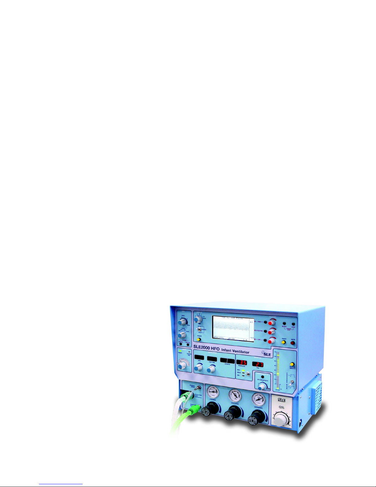
1. Introduction
The SLE2000 HFO ventilator is designed for use on
neonates/infants. Its principle of operation is time
cycled, pressure limited ventilation using a constant
fresh gas flow.
Main features are that it has no expiratory valve but
uses a reverse flow of mixed gas that is injected into
the expiratory limb of the patient circuit from the
exhaust manifold. This flow of gas has the effect of
compressing 5 l/min humidified gas into the patient
ET tube.
The advantage of this system is that there is no
expiratory resistance due to valves or diaphragms,
therefore no inadvertent PEEP is generated. Also
the fresh gas flow does not require adjusting for
various rates. Another advantage is that the driving
flow in the exhaust manifold is controlled by a
regulator and therefore provides constant pressure
at all breathing rates.
The oscillatory feature is provided by a rotating jet,
driven by a motor, situated at the rear of the exhaust
block. From this jet a stream of driving gas is rotated
into the exhalation manifold which provides both, an
active inspiratory and active expiratory flow. It can
also be combined with a conventional mode such
that we can have oscillation superimposed on the
inspiratory pressure plateau, or during the expiration
phase, or a combination of both. Finally with the
ventilator operating in the CPAP mode, the
SLE2000 HFO can act as a pure oscillator where
the mean airway pressure is adjusted via the CPAP
control, and the differential pressure can be set by
the oscillation regulator.
Another main feature of the ventilator is its patient
trigger system. This functions without any
transducer in the patient circuit, on the principle of
monitoring the rate of change of pressure during the
onset of inspiratory effort. In fact it measures
inspiratory flow by this means and not a pressure
plateau.
Additionally the SLE2000 HFO has a built in oxygen
monitoring cell, fresh gas and leak alarms.
1.1 intended use
The ventilator is designed for use on neonatal and
paediatric patients from 300g to 10 kg in the
following invasive modes: CPAP, CMV, PTV, SIMV
& HFO.
The ventilator is designed to be used in a clinical
environment (example a hospital NICU or similar)
where medical grade gas and power supplies are
present.
1.2 Principles of Operation SLE 2000
HFO
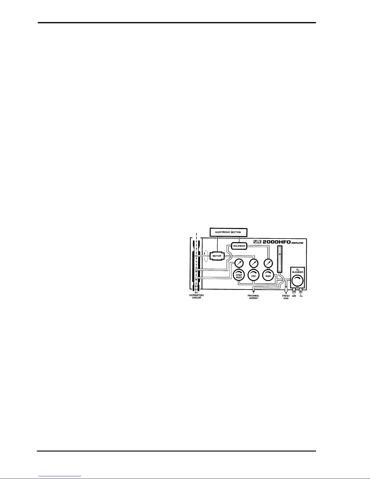
The patient circuit is supplied with a constant fixed
flow of fresh gas at 5 litres per minute. This gas
comes from the internally mounted Oxygen Blender
and its concentration is monitored by a fuel cell and
displayed on the FlO2digital display. This Fresh
Gas Supply is then passed through a humidifier to
the Inspiratory port of the patient ET connector. Built
into the ventilator are circuits to detect either a gas
flow failure or a tubing blockage. This circuitry
requires a restrictor fitted into the Inspiratory port of
the patient circuit. Therefore, only SLE2000
approved patient circuit must be used with this
equipment.
The Exhalation block mounts onto two pressure
manifold blocks. The front block has two nozzles.
The first is used to generate CPAP/PEEP via the
CPAP/PEEP regulator, by generating an opposing
flow to the fresh gas in the exhalation tube thus
creating CPAP/PEEP. The second is used to
generate the peak Inspiratory pressure. The
Inspiratory regulator sets the pressure that is
supplied to a solenoid valve which is connected to
the rear nozzle.
The Electronic Section controls the rate and
duration of opening of the solenoid valve.
When the valve is open the Driving Gas enters the
expiratory tube in opposition to the Fresh Gas flow.
This opposing flow acts as a pneumatic piston and
creates a pressure plateau at the ET connector
The lung inflation pressure and hence the tidal
volume are controlled by the Inspiratory regulator in
conventional ventilation.
The same gas mixture from the Oxygen Blender is
used to supply the patient Fresh Gas, CPAP,
Inspiratory and Oscillation driving gas pressure.
This avoids any possibility of dilution of the Fresh
Gas mixture.
There is a wave shape switch. This modifies the
Driving Gas flow rate from the Solenoid valve
through the nozzle and is used to slow down the rise
time of the pressure waveform. In the taper position
The rise time is approximately 250 ms.

Page 9
The second or rear manifold block is the High
Frequency Oscillator pressure generator. Creating a
pressure by means of a spinning jet of gas thus
providing an active positive and negative waveform
(Sinusoidal). Pressure is controlled via the oscillator
regulator and frequency via the Frequency or Rate
control.
When operating the HFO in Inspiratory or expiratory
mode, gas release is controlled via a solenoid
synchronised with the Inspiratory time and BPM.
2. User/Owner Responsibility.
This SLE 2000 HFO INFANT VENTILATOR and the
authorised accessories for it are designed to be
used in accordance with supplied manuals and
instructions. This equipment must be periodically
checked, recalibrated, maintained and components
repaired and replaced when necessary for the
equipment to operate safely and reliably.
Parts that have failed, in whole or in part, or exhibit
excessive wear, or are contaminated, or are
otherwise at the end of their useful life, should not
be used and must be replaced immediately with
parts supplied by SLE, or parts which are otherwise
approved by SLE. Equipment which is not
functioning correctly or is otherwise in need of repair
or maintenance must not be used until all necessary
repairs and/or maintenance have been completed
and a factory authorised service representative has
certified that the equipment is fit and ready for use.
This equipment, its accessories or component parts
should not be modified. The use of non-approved
parts or accessories will invalidate the warranty.
The owner/user of this equipment shall have the
sole responsibility and liability for any damage or
injury to persons or property (including the
equipment itself) resulting from operation not in
accordance with the operating instructions, or from
faulty maintenance not in accordance with the
authorised maintenance instructions, or from repair
by anyone other than the factory authorised service
representative, or from unauthorised modification of
the equipment or accessories, or from the use of
components or accessories that have been either
damaged or not authorised for use with this
equipment by the manufacturer.

Page 10
3. Warnings
3.1 Operational Warnings
The following warnings must be read and
understood before using the SLE2000 HFO
ventilator. Failure to do so could lead to injury or
death.
1 The whole of this manual should be read and
understood before using the SLE2000 HFO
Operators must be suitably trained and
clinically authorised for using the SLE2000
HFO with patients. Particular care should be
taken to check the ventilator pressures prior to
changing modes.
2 Oxygen - Clinical use. Oxygen is a drug and
should be prescribed as such.
3 Oxygen - Fire Hazard. Oxygen vigorously
supports combustion and its use requires
special precaution to avoid fire hazards. Keep
all sources of ignition away when oxygen is in
use. Do Not use oil or grease on oxygen
fittings or where oxygen is used.
4 Audible and Visual warning alarms indicate a
potentially harmful condition to the patient.
However when ventilating a patient with a
3mm or smaller size endotracheal tubes, in
case of patient extubation or the ET tube
disconnecting from its ET connector, only the
monitoring of flow (module SLE 2100), or of
SpO2, or Pt02/PtCO2will dependably alert the
medical team to an alarm situation, not the
monitoring of pressures.
5 When the ventilator is being used on a patient,
a suitably trained person must be in
attendance at all times to take prompt action
should an alarm or other indication of a
problem occur.
6 The ventilator functional tests must be carried
out each time the SLE 2000 HFO is used on
patients. If any of these tests do not function as
described then there is a problem and the
ventilator must not be used until it is rectified.
7 The humidifier used in the patient circuit must
be operated and maintained in accordance
with its manufacturer’s instructions.
8 An alternative form of ventilation should be
available whenever the ventilator is in use.
9 Any water trap used in the patient circuit must
be drained regularly before it is full.
10 Failure to comply with the recommended
service programs could lead to injury to the
patient, operator or damage to the ventilator. It
is the owners responsibility to ensure that the
equipment is regularly maintained.
11 Functioning of this ventilator may be adversely
affected by high frequency surgical
(Diathermy) defibrillators, short-wave therapy
or equipment producing strong magnetic fields,
operating in the vicinity.
12 The Ventilator must be connected to a suitably
rated and grounded electrical power source.
13 There is no special protection provided against
ingress of water or liquids.
14 The equipment is not suitable for use with, or
in the presence of flammable anaesthetic
mixtures.
15 Do not cover the ventilator during use or allow
the ventilator to become covered by any fabric
or curtain. Do not allow the exhaust ports or
inlet vents to become obstructed or blocked by
positioning the ventilator near curtains or
fabric.
16 No external voltage should be applied to the
auxiliary socket. Any connections to this socket
must be approved by SLE and screened to
comply with EMC regulations. Ensure
protection cap is fitted when socket is not in
use.
17 The electronic module of the ventilator
contains a primary battery, if the ventilator is
not to be used for 3 months or more, then the
battery should be removed.
18 Care should be taken when attaching other
equipment as this may affect stability.
19 Use only SLE approved patient circuits. On no
account should antistatic or electrically
conductive tubing be used in the patient circuit.
20 The patient circuit should not be modified.
Modified patient circuits or circuits with
additional sections or components may
produce too high a circuit resistance and circuit
compliance for effective ventilation.
21 Use of non approved patient circuits may
cause inadvertent block or leaks alarms.

Page 11
3.2 Clinical Warnings
Failure to take corrective action when the alarms
are activated could result in injury or death to the
patient.
3.3 Monitoring
The minimum patient monitoring requirements are:
1 ECG/heart rate.
2 Blood pressure (either by invasive or non
invasive means).
3 Oxygen saturation.
4 Transcutaneous carbon dioxide arterial /
capillary blood sampling.
5 Standard nursing care for Intensive Care
patients.
3.4 Clinical considerations
1 When switching from conventional to high-
frequency ventilation, or vice-versa, alterations in
ventilator settings and inspired oxygen
concentrations may be required.
2 All ventilation should only be instituted by fully
trained and experienced medical personnel.
3 Incorrect humidification.
4 Intra-ventricular haemorrhage, cerebral
ischaemia;
5 Volutrauma resulting in (bronchopulmonary
dysplasia in the newborn);
6 The use of an uncuffed ET tube.
7 Maintenance of an adequate airway is of
paramount importance.

Page 12
This page is intentionally blank.

Page 13
Operation
Page 14
4. Operation
4.1 Functional Tests
With HFO and Mode switches set to OFF, High
alarm set to maximum and all other variable controls
set to minimum.
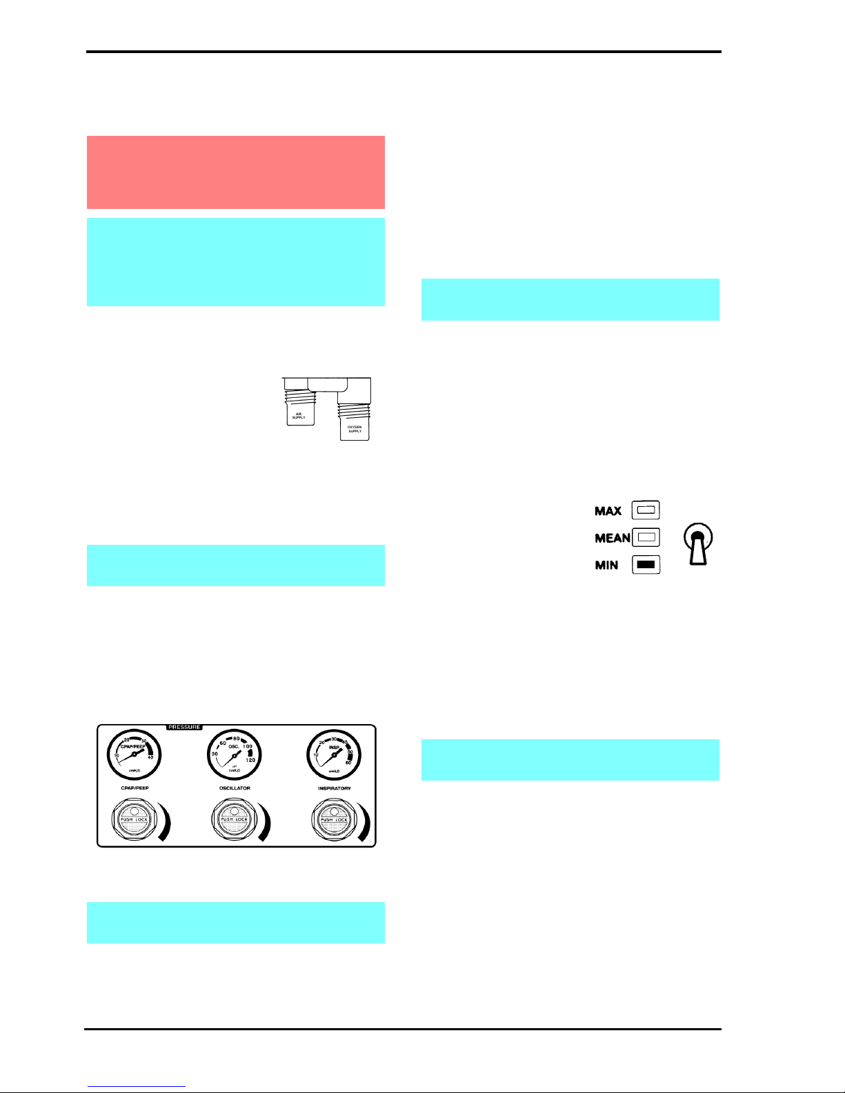
Step 1. Connect AIR,
OXYGEN Hoses to
ventilator and plug
into gas supplies, at
a gas pressure of
about 4 bar.
Connect mains cable to a suitably rated
and grounded electrical power source.
Step 2. Connect SLE approved patient circuit with
test lung to the ventilator.
4.2 Pressure Regulators and Gauges
Check in turn the CPAP/PEEP, OSCILLATOR and
INSPIRATORY regulators and gauges by turning
the regulator controls from minimum to maximum
and making sure that the gauges read between
minimum and maximum. Return regulators to
minimum.
Regulator Controls are lockable. Push to lock,
Pull to unlock.
4.3 Automatic Power On Test
Select ventilator mode to CPAP.
The ventilator will now carry out a self test as
follows.
Power LED shows green and an automatic test of
functions & alarms is initialised. Firstly the displays
and audible alarms are turned on for approximately
two seconds to demonstrate that they are operable,
then for a further three seconds all the digital
displays show a sequence of numbers from O to 9
before returning to their normal state.
4.4 Setting Alarm Limits
•Set the High Alarm to maximum 60 cmH2O
•Set the Cycle Fail Alarm to approximately 28
cmH2O
•Set the Low Alarm to minimum -60 cmH2O
4.5 CPAP Mode
Set CPAP/PEEP Regulator
to give 30 cmH2O on the
pressure display with the
pressure display selector
switch in the MIN position.
Set Inspiratory Regulator to 20 cmH2O
Ensure that:-
•Bargraph display reads 30 cmH2O ± 2 cmH2O
•CPAP/PEEP gauge reads 30 cmH2O
•An Inspiratory cycle is initiated when manual
breath button is pressed
Warning: The following functional tests must
be carried out to ensure that this equipment
is working correctly before connection to a
patient.
Note: If any of these tests do not function as
described, there is a problem and the unit
should not be used until it has been repaired.
please contact an sle approved engineer, or
SLE.
Note: See instructions supplied with patient
circuit.
Note: These gauges are for indication only
and not for measuring operating pressures.
Note: HFO Fail and Block LEDs do not come
on during this sequence.
Note: Alarm limits will also be shown on the
bargraph display.
Page 15
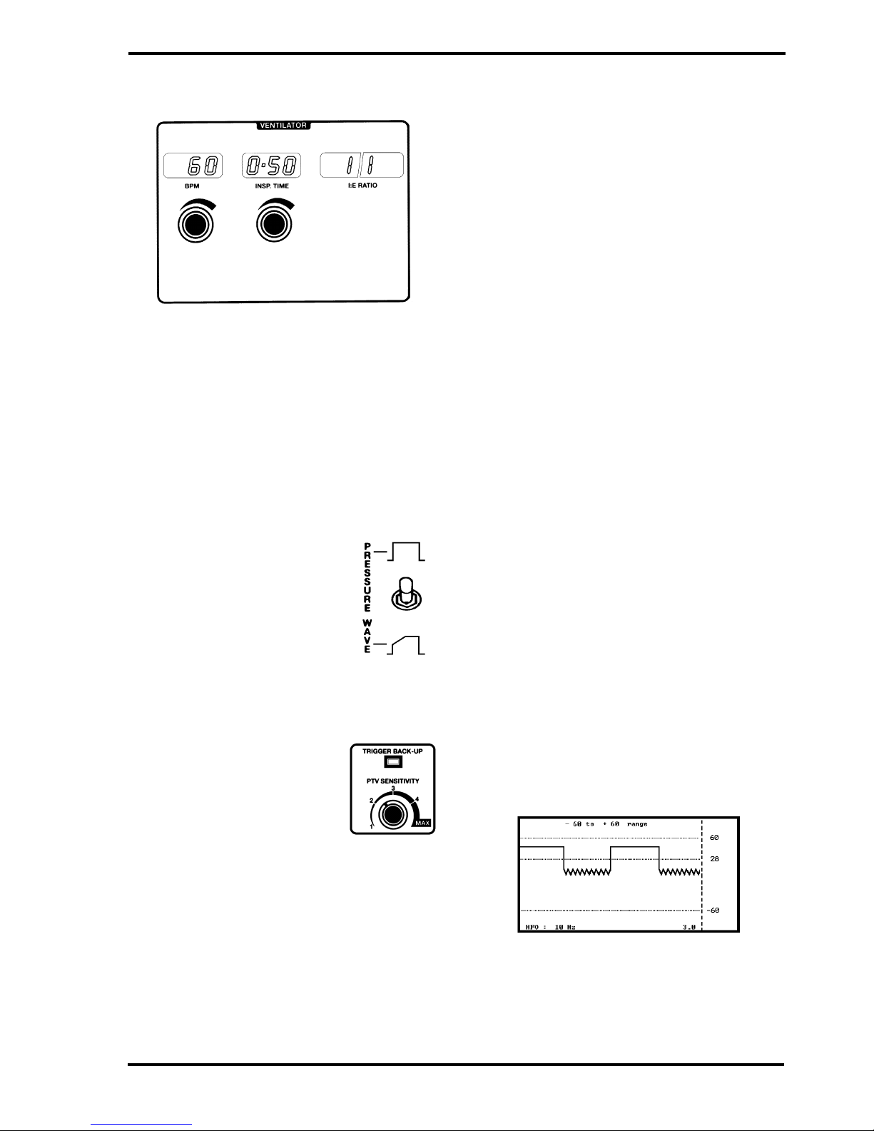
4.6 CMV Mode
Set the following ventilator conditions :
•CPAP/PEEP regulator to 0 cmH2O
•Inspiratory regulator to 30 cmH2O
•Mode switch to CMV
•BPM Rate to 60
•INSP TIME to 0.50
•Cycle Fail Alarm to mid waveform
•Press Reset to cancel all alarms
Ensure that :-
•The ventilator is cycling
•I:E Ratio display reading 1:1
•Pressure waveform is shown on
graphics display
•Pressure waveform shape
changes with operation of
PRESSURE WAVE SWITCH.
(Return the switch to the square
wave setting.)
4.7 PTV Mode
Set BPM rate to 20
•Set the CPAP/PEEP regulator
to 10 cmH2O on the gauge
•Set the PTV Sensitivity to 3
•Select PTV with mode switch.
Ensure that :-
•Ventilator should continue to cycle
•BPM display reading is initially 0
•TRIGGER BACK-UP LED is “ON”
Apply slight pressure to test lung and release to
simulate patient inspiratory effort.
Ensure that with each operation :-
•The ventilator cycles once.
•The TRIGGER BACK-UP LED is “OFF”.
4.8 SIMV Mode
Select SIMV with mode switch.
Ensure that:-
•The ventilator continues to cycle.
•The BPM display shows set rate.
•The TRIGGER BACK-UP LED illuminates on
each inspiration.
Apply a varying pressure to test lung to simulate
patient breathing.
Ensure that:-
•The ventilator continues to cycle at the set rate
but synchronised with the pressure from test
lung.
•The TRIGGER BACK-UP LED is “OFF”.
4.9 HFO Modes
Set the following conditions:-
•CMV Mode
•BPM rate to 30
•INSP Time to 1.00
•Oscillator Regulator to » 30 cmH2O
•Inspiratory Regulator to » 20 cmH2O
•HFO Mode to EXP
•HFO Rate to 10 Hz
•Display Switch to 3 seconds
•Screen Switch to ±60 cms
•Press Alarm Mute Button
Ensure that :
•The ventilator is cycling.
•10 Hz oscillation shown on expiratory cycle of
waveform.
Page 16
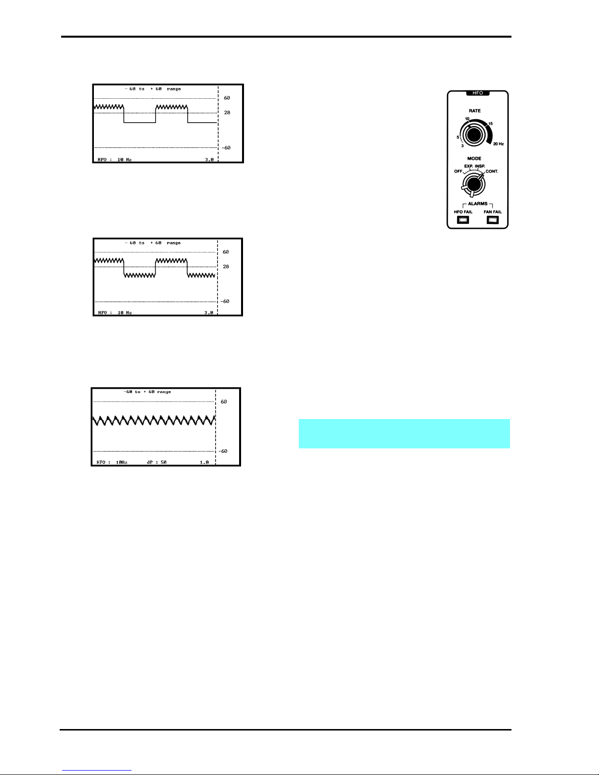
Set HFO mode to INSP
Ensure that :
•10 Hz oscillation shown on inspiratory cycle of
waveform.
Set HFO mode to CONT
Ensure that :
•10 Hz oscillation shown on both inspiratory and
expiratory cycles of waveform.
Set mode switch to CPAP.
Ensure that :-
•Continuous 10 Hz waveform is seen on the
screen.
Press the reset button to autoset the alarms.
4.10 Alarm Test
4.10.1 To Verify Alarms
Set the following ventilator
conditions :-
•HFO mode OFF.
•CPAP/PEEP regulator to 10
cmH2O.
•Inspiratory regulator to30
cmH2O.
•Oscillator Regulator to 0
cmH2O
•Mode switch to CMV
•Rate to 60 BPM
•INSP. TIME to 0.50
•Ensure ventilator is cycling and check the
following alarms
•Set Cycle fail alarm to mid waveform
•Reset all alarms
4.10.2 High Alarm
Reduce high alarm setting so that alarm cursor line
is below the peak pressure wave on the screen.
This should initiate an audible alarm and a HIGH
and LEAK visual indication. Return alarm setting to
maximum position. Reset alarm by the reset button.
4.10.3 Cycle Fail Alarm
Increase the alarm setting so that alarm cursor line
is above peak pressure wave on the screen. This
will initiate an audible and CYCLE FAIL visual alarm
indication. Return alarm setting to within the
pressure wave, audible alarm should self cancel.
Reset visual alarm by the reset button
Decrease the alarm setting so that alarm cursor line
is below pressure wave on the screen. This should
initiate an audible and CYCLE FAIL visual alarm
indication. Return alarm setting to within the
pressure wave, audible alarm should self cancel.
Reset visual alarm by the reset button.
Note: The Fresh Gas flow is reduced from 5
l/min to 1 l/min in the High Alarm condition.

Page 17
4.10.4 Low Alarm
Increase low alarm setting so that alarm cursor line
is above the minimum pressure wave on the screen.
This should initiate an audible and LOW visual
alarm indication. Visual alarms once set can only be
cancelled by pressing the reset button. Return
alarm setting to required position. Reset visual
alarm by the reset button.
4.10.5 Leak/block Alarm
Disconnect the fresh gas tubing from the ventilator.
This should initiate an audible and LEAK visual
alarm indication. Occlude the fresh gas outlet. This
should initiate an audible and BLOCK visual alarm
indication. Reconnect tubing, audible and visual
alarms should self reset.
4.10.6 Mains Failure Alarm
DO NOT TURN MODE SWITCH TO OFF.
Disconnect mains power by switching off or
removing mains plug from power socket.
This should initiate an audible alarm. Reconnect
mains power supply, ventilator should carry out self
test and resume previous mode of operation.
4.10.7 O2Blender Alarm
Set Blender to 60%. Disconnect Air supply from
wall outlet, an audible alarm should be heard from
Blender. Reconnect Air Supply, alarm should self
cancel. Disconnect O2supply, an audible alarm
should be heard from blender. Reconnect O2
supply, alarm should self cancel.
4.10.8 Oxygen Concentration Alarm
Set the Oxygen concentration to 60% and press the
reset button. Wait 1minute for the reading to
stabilise. Increase the Oxygen concentration to
100%, the alarm should sound. Decrease the
Oxygen concentration to 21%, the alarm should
cancel as the Oxygen concentration crosses the
alarm threshold and then sound again as the
Oxygen concentration gets too low. Press Reset.
4.11 O2Cell
4.11.1 Condition Of O2Cell.
Set blender to 100% and observe that displayed
FIO2is 100%. Set blender to 21% and observe that
displayed FIO2is 21%. To adjust, set blender
control to 100%. Remove Air Supply Hose and
allow 3 minutes before adjusting control on rear
panel. If unable to set 100%, O2Cell must be
replaced. Ignore any blender alarms during this
adjustment.
Page 18
5. Basic Set Up for the SLE 2000
HFO
Step 1. Connect AIR and
OXYGEN hoses to
ventilator and plug
into gas supplies, at a
gas pressure of about
4 bar. Connect
mains cable to a suitably rated and
grounded electrical power source.
Step 2. Connect SLE approved patient circuit to
the Ventilator and Humidifier.
• For further information see instructions
supplied with patient circuit.
• To test the system the patient manifold must
be occluded or a Test Lung fitted.
• Only an SLE approved patient circuit should
be used with this equipment
Step 3. Set up humidifier to manufacturer’s
instructions
Step 4. Set the following ventilator conditions :-
•High alarm to maximum
•Low alarm to minimum
•HFO mode OFF
•Three pressure regulators to minimum
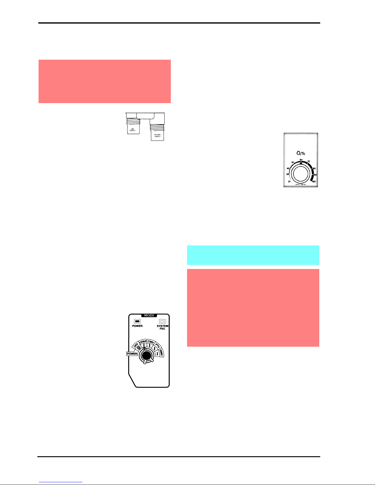
Step 5. Select mode of
ventilation to CPAP
The ventilator will now carry out
a self test as described on
page 14. Ensure that this test is
completed satisfactorily before
continuing.
If after completion of the above self test an alarm
continues, a red light might indicate either BLOCK
or LEAK in the fresh gas tubing of the patient circuit.
Ensure that all patient fittings are correctly made
and secure.
Do not continue until alarms are cleared
•The ranges of the graphic display can be set
using the display controls. A Freeze button
allows the waveform to be held. Press to freeze,
press again to un-freeze.
•Do not carry out any adjustments with the
display in the freeze mode.
Step 6. (a) Set required O2
concentration by means of
O2Blender Control. %O2
Oxygen will be monitored
and displayed in FlO2
Digital Display.
The oxygen monitor will
alarm if the oxygen
concentration rises or falls
by more than 5% and a
warning message will be
displayed on the LCD.
The ventilator should now be ready to connect to a
patient.
Warning:It is the operator’s responsibility to
check the ventilator pressures prior to
changing modes.
The ventilator must not be connected to the
patient during this set up procedure.
Changes will take 30 seconds to stabilise on
the FlO2display.
Oxygen - Clinical use. Oxygen is a drug and
should be prescribed as such.
Exposing a baby to elevated concentrations
may lead to Retrolental Fibroplasia.
Oxygen - Fire Hazard. Oxygen vigorously
supports combustion and its use requires
special precaution to avoid fire hazards. Keep
all sources of ignition away when oxygen is in
use. Do Not use oil or grease on oxygen
fittings or where oxygen is used.

Page 19
5.1 To Use the SLE 2000 HFO in CPAP
Mode
As steps 1 to 6 in basic setup
Step 7. (a) Set pressure
display switch to
minimum
(b) Increase CPAP/
PEEP pressure to required level
Pressure will be indicated on the digital display, the
graphic display and bargraph.
(c) Set Low alarm to the required level.
The alarm levels are digitally and pictorially
displayed on the graphic display.
A manual breath can be delivered, of the set
inspiratory time, by pressing the Manual Breath
Button.
5.2 To Use the SLE 2000 HFO in CMV
Mode
As steps 1 to 7 basic set-up and CPAP then:
Step 8. (a) Set INSP. TIME to required rate
(displayed in seconds)
(b) Select Pressure Wave
Shape SQUARE or TAPER
(c) Switch mode switch
from CPAP to CMV
(d) Adjust the BPM to required rate.
(e) Set the pressure display switch to MAX and
increase the INSP pressure to the desired level.
This is indicated on the digital pressure display, the
graphic display and the bargraph.
(f) Set the CYCLE FAIL and HIGH alarms to
required levels. Press RESET to clear the alarms
lights.
These Controls are lockable. Push to lock,
Pull to unlock.
Note: Ventilator will start to cycle and the
alarms will probably sound - press MUTE to
silence them.

Page 20
HIGH will activate if setting is exceeded and also
open a pressure relief valve and activate LEAK
alarm
CYCLE FAIL will activate if pressure wave fails to
pass through threshold on inspiration and expiration
LOW is activated if pressure falls below setting
5.3 Patient Trigger Modes
5.3.1 To Use SLE 2000 In PTV or SIMV Mode
As steps 1 to 7 then:-
Step 9. (a) Set PTV sensitivity to min
(b) Set the BPM control to provide either:-
The desired back-up rate for
PTV
or
The desired number of
mandatory breaths per minute
for SIMV
(c) Switch mode from CMV to PTV or SIMV
Once connected to a patient, increase the PTV
sensitivity towards Max until patient effort triggers
the ventilator. This is indicated by the TRIGGER
BACK-UP light extinguishing.
•The weaker the patient the higher the sensitivity
required.
After 60 seconds with an update every 60 seconds,
the BPM LED display will indicate the number of
patient initiated breaths that were delivered in the
preceding minute.
Care should be taken not to set the PTV sensitivity
too high as it will self trigger.
5.4 To Use the SLE 2000 HFO in the
Oscillator Mode
THERE ARE 4 OSCILLATORY
MODES
5.4.1 EXP.
Expiratory oscillation combined with conventional
ventilation.
(a) Set ventilator mode to CMV (see page 19)
(b) Set HFO mode to EXP
(c) Set HFO frequency using rate control.
(d) Set amplitude using oscillation pressure
regulator
Oscillation is added to the conventional pressure
waveform. The frequency of oscillation will be
shown on the screen.
Other manuals for SLE2000 HFO
2
Table of contents
Other SLE Medical Equipment manuals


Popular Medical Equipment manuals by other brands


Getinge
Getinge Arjohuntleigh Nimbus 3 Professional Instructions for use

Mettler Electronics
Mettler Electronics Sonicator 730 Maintenance manual

Pressalit Care
Pressalit Care R1100 Mounting instruction

Denas MS
Denas MS DENAS-T operating manual

bort medical
bort medical ActiveColor quick guide

AccuVein
AccuVein AV400 user manual


