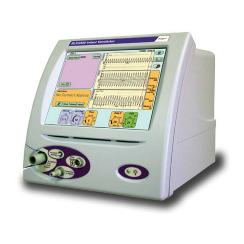
SLE SLE5000 Model J User manual

SLE5000
Model J service manual
Version 4.3.1 & 4.3.2 software

Page 2 (Model J)
Software/Manual application Information:
Contact Information:
All rights reserved. No part of this publication may be reproduced, stored in any retrieval system, or transmitted
in any form or by any means, electronic, mechanical, photocopy, recording or otherwise, without prior
permission of SLE. © Copyright SLE 30/09/2016.
Manual: SM31 Issue 3
SLE Part Nº: N6645/J
Note: This manual is to be used only with models J ventilators using the following
software version:
Version 4.3.1 & 4.3.2
SLE Limited
Twin Bridges Business Park
232 Selsdon Road
South Croydon
Surrey CR2 6PL
Telephone: +44 (0)20 8681 1414
Service Fax: +44 (0)20 8649 4517
Web site: www.sle.co.uk
Revision history.
Issue 3: CR 371, 451 & 586. ECN167.

(Model J) Page 3
Contents
1. Warnings and Cautions .............................................................................................10
1.1. Warnings ........................................................................................................10
1.2. Cautions .........................................................................................................11
2. Principles of Operation ..............................................................................................14
2.1. Electronic System...........................................................................................14
2.2. Pneumatic System .........................................................................................15
3. Description of Symbols .............................................................................................18
4. Equipment list ...........................................................................................................22
5. ENGMODE ...............................................................................................................24
5.1. Accessing the Calibration Programs ..............................................................24
5.2. Ventilator Calibration Program .......................................................................26
5.3. O2 & Flow System Calibration........................................................................27
5.4. Reset Elapsed Time.......................................................................................28
5.5. Language Selection........................................................................................28
5.6. Activation of Language Selection Program form User Interface.....................29
5.7. Exit .................................................................................................................29
5.8. Touch Screen Calibration Program................................................................30
6. Component Replacement Procedure ........................................................................32
7. Preparing the SLE5000 .............................................................................................33
8. Component Replacement (Electronic unit) ...............................................................35
8.1. N6631/21/CF/50 Compact Flash Card...........................................................35
8.2. N6631/LX800 PC Board.................................................................................35
8.3. N6634/OEM2 CAN Card ................................................................................36
8.4. N6631/2216 Serial controller (Touch screen).................................................36
8.5. L0275/OEM2 Computer/Display Control assembly........................................37
8.6. A0763/02/M Control/Monitor Board................................................................38
8.7. M0915 Power Supply Unit..............................................................................39
8.8. M0901 Batteries .............................................................................................40
8.9. A0761 Transducer PCB Assembly.................................................................41
8.10. N6631/13 Inverter PCB ................................................................................42
8.11. N6631/02 LCD & N6631/05 Touch Screen ..................................................43
9. Component Replacement (Pneumatic unit) ..............................................................45
9.1. Duckbill and conical filters..............................................................................45
10. A0763/02/M Monitor and control board ...................................................................56
10.1. A0763/02/M board programmable devices...................................................56
10.2. A0763/02/M Board Hardware Identifier........................................................57
11. Electrical Safety Testing of the SLE5000 ................................................................61
12. PSU Testing ............................................................................................................65
13. Ventilator Power up and Power down. ....................................................................68
14. Back-up Battery Charging .......................................................................................69

Page 4 (Model J)
14.1. Battery indicator............................................................................................69
15. Extended storage ....................................................................................................71
16. Maintenance and Overhaul .....................................................................................74
16.1. Preventative Maintenance Kit.......................................................................74
16.2. 12 & 36 month preventative maintenance procedure...................................76
16.3. 24 month and 48 month overhaul procedures ..............................................84
16.4. 24 month / 10,000 hour overhaul procedure.................................................86
16.5. 48 month / 20,000 hour overhaul procedure.................................................94
16.6. 48 month overhaul procedure using N9410/48/G overhaul kit......................96
17. Calibration Procedure for V4.3.1 & V4.3.2 software ................................................108
17.1. Equipment required for calibration................................................................108
17.2. Preliminary Inspection before calibration......................................................109
17.3. Pneumatic set up..........................................................................................110
17.4. Calibration of Controller and Monitor subsystems........................................113
17.5. Controller “Block and Leak” pressure sensor calibration ..............................115
17.6. Controller Blender Pressure Sensor zeroing and Input pressure reg. trim ...116
17.7. Mean Jet Pressure Regulator Calibration.....................................................117
17.8. Forward Jet Pressure Regulator Calibration.................................................119
17.9. Reverse Jet Pressure Regulator Calibration.................................................120
17.10. Time Constant for pressure measurement waveform.................................121
17.11. Wave shaping for leading and trailing edge of insp. phase ........................121
17.12. O2 System Calibration................................................................................123
17.13. Flow System Calibration .............................................................................123
17.14. Pressure Triggering Verification..................................................................123
17.15. Gas Fail Detection Verification....................................................................123
17.16. Blender and Oxygen Monitoring Verification...............................................124
17.17. Soak Test....................................................................................................125
17.18. Battery Charge Verification.........................................................................126
17.19. Total Power Fail Alarm Test........................................................................126
17.20. Pressure Calibration Verification.................................................................127
18. Functional Testing ...................................................................................................130
18.1. Ventilator setup.............................................................................................130
19. Trouble Shooting Chart ...........................................................................................162
20. Software Version History .........................................................................................172
21. Oxygen Calibration Routines ...................................................................................174
21.1. One point or 100% Oxygen system calibration.............................................174
21.2. Two point or 21% & 100% Oxygen system calibration.................................174
22. Alarms .....................................................................................................................176
22.1. Alarm Protocols.............................................................................................176
22.2. Alarm Sounds ...............................................................................................176
22.3. Alarm Descriptions and actions to be taken..................................................177
22.4. Software and System Fail Protocols.............................................................196

(Model J) Page 5
23. Cleaning, disinfection and sterilization ....................................................................197
23.1. Preparation of a new ventilator.....................................................................197
23.2. Cleaning and disinfection of an in-service ventilator ....................................197
23.3. Cleaning method ..........................................................................................198
23.4. Disinfection method......................................................................................199
23.5. Sterilization method......................................................................................200
24. Technical Specification ...........................................................................................201
24.1. Operating Modes Conventional Ventilation..................................................201
24.2. HFO Ventilation............................................................................................203
24.3. Measurement ...............................................................................................207
24.4. Exhalation Block Port Jet Sizes....................................................................208
24.5. Alarms ..........................................................................................................209
24.6. Patient circuits..............................................................................................210
24.7. Outputs.........................................................................................................211
24.8. Gas supplies.................................................................................................212
24.9. Power, Dimensions, Classification etc..........................................................213
24.10. Classification ..............................................................................................213
24.11. Environmental Storage Conditions.............................................................213
25. EMC compliance .....................................................................................................214
25.1. Electromagnetic immunity ............................................................................215
25.2. Recommended separation distances between portable and mobile RF
communications equipment and the SLE5000......................................................217
26. Ventilator labelling ...................................................................................................218
27. Electrical Block Diagram .........................................................................................220
28. L0280/KV Pneumatic Unit Layout & Schematic ......................................................221
28.1. Layout ..........................................................................................................221
28.2. Schematic ....................................................................................................222
29. Main Loom Circuit Diagram ....................................................................................223
30. L0275/OEM2 Assembly Schematic ........................................................................224
31. A0761 circuit diagram .............................................................................................226
31.1. Transducer PCB Assembly ..........................................................................226
32. A0763/02 circuit diagrams ......................................................................................228
32.1. Micro Controller............................................................................................228
32.2. Conventional Valve Drive.............................................................................229
32.3. Power Distribution And Hardware Identifier..................................................230
32.4. Analogue Valve Drive / Non Volatile Memory / Interboard Comms..............231
32.5. High Speed Valve Drive ...............................................................................232
32.6. Analogue Data acquisition/Monitor port........................................................233
32.7. Control & Monitor, PCB PSU Circuit.............................................................234
32.8. Control & Monitor, Micro Non-isolated..........................................................235
32.9. Control & Monitor, Micro Isolated.................................................................236
32.10. Control & Monitor, Analog Isolated.............................................................237
32.11. Control & Monitor, Alarm Controller............................................................238
Other manuals for SLE5000 Model J
1
Table of contents
Other SLE Medical Equipment manuals
Popular Medical Equipment manuals by other brands

Getinge
Getinge Arjohuntleigh Nimbus 3 Professional Instructions for use

Mettler Electronics
Mettler Electronics Sonicator 730 Maintenance manual

Pressalit Care
Pressalit Care R1100 Mounting instruction

Denas MS
Denas MS DENAS-T operating manual

bort medical
bort medical ActiveColor quick guide

AccuVein
AccuVein AV400 user manual


