7
• With 4 Allen screws [1] tighten the
centering adapter [2] to the chosen
port of the slider’s rail [3],
• if the slider consists of one section
only, tighten the adapter to the mid-
dle port,
• if the slider consists of several sec-
tions, choose the mounting points
carefully to attain stable support,
• note that each section should be
supported at least in one point,
• to mount the slider on the tripod
place the adapter underneath the tripod’s socket; tighten the adapter as an
ordinary head; use a universal 3/8” screw.
2
2
3
3
4
4
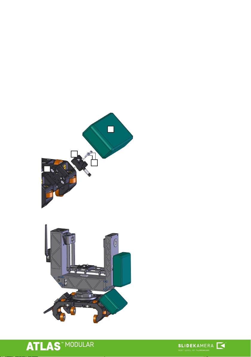
3.3. Motion end blocks
3.4. Adjustable feet
3.5. Centering adapters
To secure the slider’s dolly put the motion end
blocks [1] in the slider’s end sections.
• Fit the end blocks into appropriate centering
holes [2].
• Tighten them with knobs [3], located on the
outer side of the end blocks.
The end blocks also have clamps for mounting
the timing belt of the slider’s drive [4].
• attach the foot’s mounting element
[2] with 4 Allen screws [1] to the
slider’ rail’s end port [3]
• place the regulated feet [4] in the
sockets
• adjust their height and tighten the
clamps [5]
Each section has 4 regulated feet which adjust to the ground. When the set
is standing on the ground, it can be quickly leveled.
The producer provided centering adapters for correct and quick mounting of the
slider to the tripods. The adapters are t for tripod sockets with a diameter of 75
and 100mm. Each section has one 75/100mm centering adapter.
2
2
33
1
TIP
The feet are necessary for the prop-
er functioning of the slider, when it
is standing directly on the ground.
They can be removed to make work
easier when the slider is mounted,
e.g. on a tripod.
TIP
As the feet and the slider’s rails’
ports are equipped with 3/8” sockets
[4] it is possible to mount the tripod
directly to the port.
Such installation is not recommend-
ed for tripods with bowls for mount-
ing 75/100mm half-balls due to the
lack of precision of mounting and a
potential lack of connection stability.
4
5
5
1
1
4