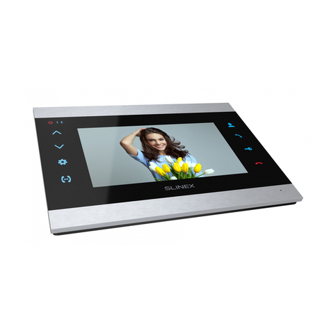
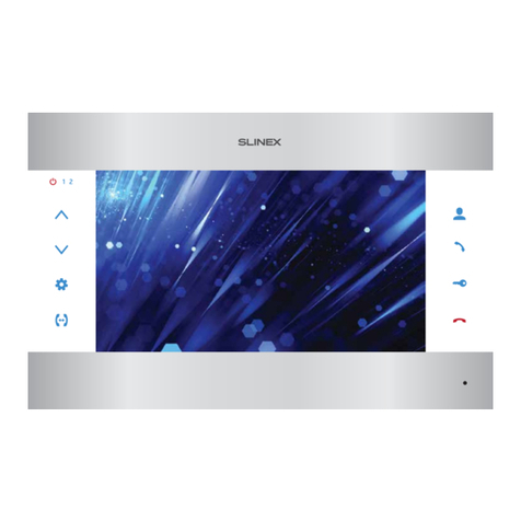
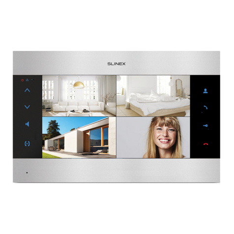
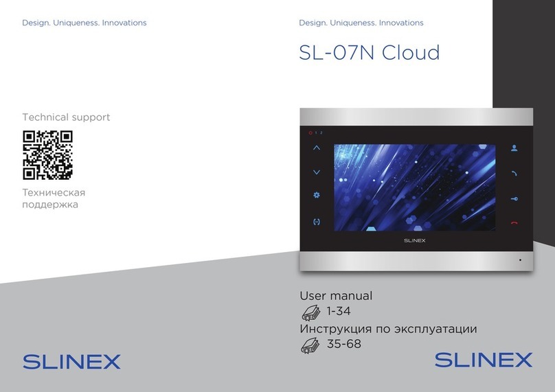
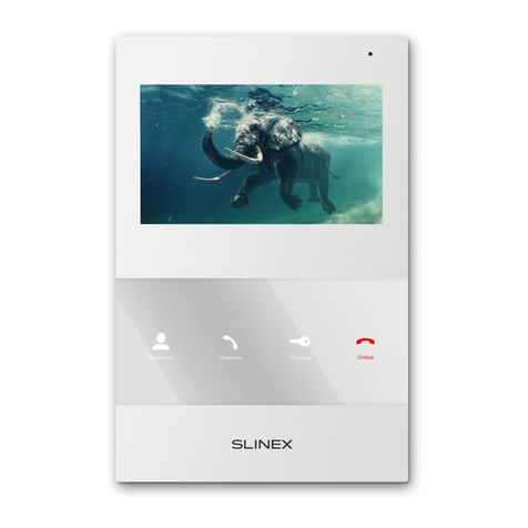
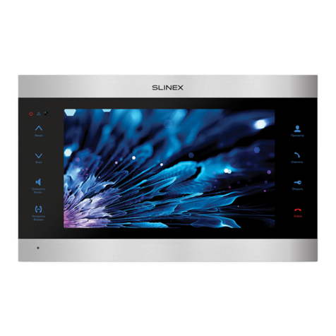
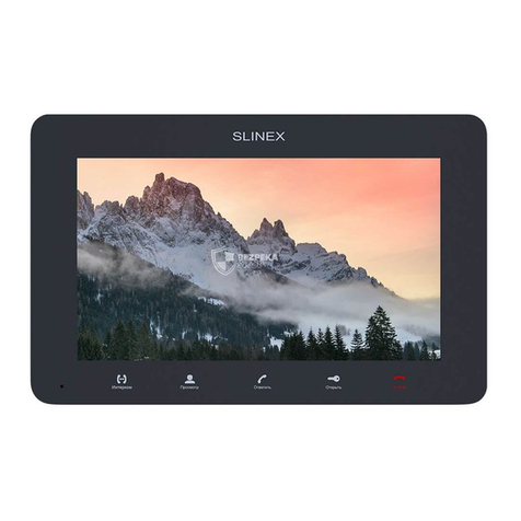
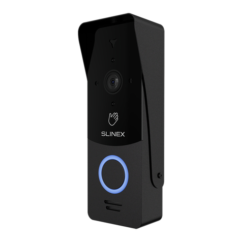
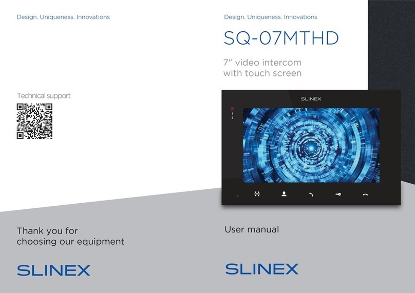
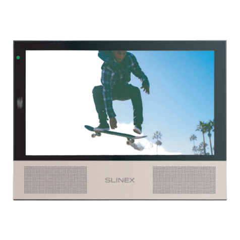
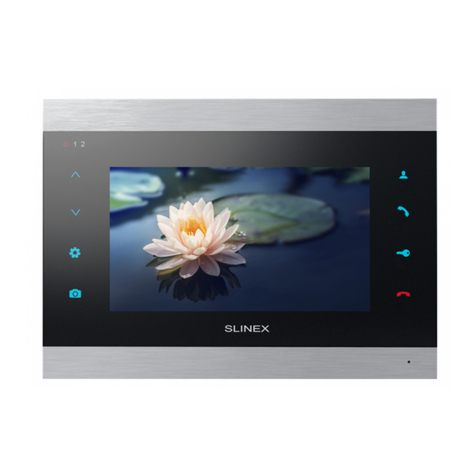
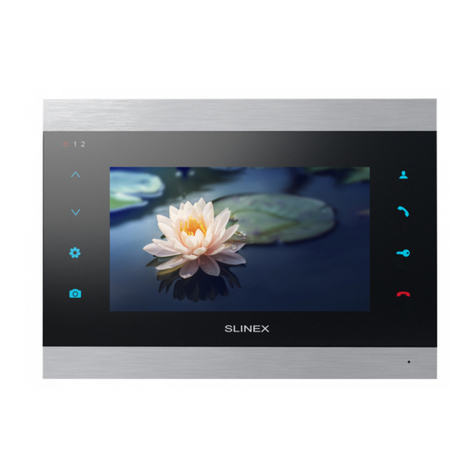
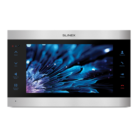
Slinex SM-07MHD User manual

Design. Uniqueness. InnovationsDesign. Uniqueness. Innovations
User manual
Technical support
Thank you for
choosing our equipment
7" video intercom
SM-07MHD

SM-07MHD
1REV. 1.0 2
Attention!
As a result of continuous upgrades and functionality improvements, technical
characteristics of the device can be changed without any preliminary declaration.
This manual can contain some inaccuracy or misprint. The owner reserves the right to
make corrections to the information described in the user manual and device package.
The last revision of this manual is available on www.slinex.com
Safety instructions
Read and keep that manual.
The device installation process should be carried out by the qulied specialists.
Use the device from –10 ˚C to +55 ˚C, always keep it within that temperature range.
Installation surface should be free from vibration and impact inuence.
Keep this device far from open sources of heat, such as radiators, heaters, and ovens.
The device can be installed near other electronic equipment in case if the temperature of the environment
does not exceed previously mentioned range.
The device should be protected from the direct inuence of the natural phenomena, such as direct
sunlight, rain or snow.
Don’t use aggressive or abradant detergent for the device surface cleaning.
Use soft wet cloth or tissue to remove strong dirt.
Don’t overpower outlets. It can cause re or electric shock.
Nature protection
Don’t throw away the device with other industrial or nutritive trash if you see that
symbol. Some regions have separation and recycling systems for the electronic
equipment. Connect with local authorities to receive information about recycling of
electronic equipment for your region.
Rights and limitation of liability
All rights reserved. Any part of that document can not be published in any form, translated into other
languages or reproduced in any way including electronic or mechanical.
Document recording and copying is strictly denied without owner permission.
!
Table of contents
1. Package ................................................................................................................................................................................... 3
2. Specication.......................................................................................................................................................................... 3
3. Description............................................................................................................................................................................. 4
4. Installation.............................................................................................................................................................................. 5
4.1. Cable requirements............................................................................................................................................. 5
4.2. Schematic diagrams............................................................................................................................................ 6
4.3. Unit mount ............................................................................................................................................................. 8
5. Operation................................................................................................................................................................................ 9
5.1. Incoming call ......................................................................................................................................................... 9
5.2. Outdoor panel and camera monitoring ...................................................................................................... 10
5.3. Incoming call redirection .................................................................................................................................. 11
5.4. Intercom .................................................................................................................................................................. 12
6. Monitor settings................................................................................................................................................................... 12
6.1. Main menu.............................................................................................................................................................. 13
6.2. System settings..................................................................................................................................................... 14
6.3. Ring and volume settings ................................................................................................................................. 16
6.4. Working mode settings...................................................................................................................................... 17
6.5. Alarm settings ....................................................................................................................................................... 18
6.6. Software motion detection settings ............................................................................................................. 19
6.7. Snapshots and records playback.................................................................................................................... 21
6.8. Using custom MP3 melody as a ringtone.................................................................................................... 22
6.9. Image viewing (photo frame).......................................................................................................................... 23
7. Display and volume settings ........................................................................................................................................... 23
8. Manual and automatic recording.................................................................................................................................. 24
9. External sensors motion detection recording........................................................................................................... 24
10. Limited Warranty............................................................................................................................................................... 25

SM-07MHD
3 4
1
2
3
4
5
6
7
8
9
10
‘
11
Display;
Microphone;
«Intercom» button – call another monitor or incoming call redirection;
«Monitor» button – outdoor panel or camera image monitoring;
«Answer» button – incoming call answer and start conversation with the visitor;
«Unlock» button – door unlocking;
«Hang Up» button – stop conversation with the visitor / exit current menu;
MicroSD card slot;
Speaker;
Volume joystick:
• press the joystick during conversation to enter talking volume setting menu, then
move the joystick up or down to increase or decrease monitor speaking volume;
• press the joystick during incoming call to enter melody volume setting menu, then
move the joystick up or down to increase or decrease ringing volume;
Settings joystick:
• press the joystick in standby mode to enter settings menu;
• move joystick up or down to move through the menu settings (next/previous
parameter);
• press the joystick on any parameter to change its value. Change the value of current
parameter by moving joystick up or down and then press the joystick again to save
current parameter value;
• move the joystick up in monitoring or conversation mode to take a snapshot or move
the joystick down to start/stop video recording.
3. Description
5
47
6
3
8
9
10
11
123 mm
193 mm 18
mm
1. Package
SM-07MHD indoor monitor − 1 pc.
Wall mounting bracket − 1 pc.
Connection wires − 1 pkg.
Mounting screws and anchors − 1 pkg.
User manual − 1 pc.
2. Specication
SCREEN
7”, color TFT
RESOLUTION
1024×600 px.
VIDEO SYSTEM
PAL / NTSC / AHD, TVI, CVI (720p,1080p)
AUDIO TYPE
Half duplex
CALL DURATION
120 seconds
MEMORY
MicroSD card, up to 64 GB
Internal memory, up to 100 snapshots
STANDBY MODE POWER CONSUMPTION
3 W
WORKING MODE POWER CONSUMPTION
8 W
POWER SUPPLY
Built-in power supply, ~100–240 V
MOUNTING TYPE
Surface mount
DIMENSIONS
193×123×18 mm (7.60×4.84×0.71")
WORKING TEMPERATURE
10 ... +55 ˚C (+14...+131 ˚F)
2
1

SM-07MHD
5 6
4.2. Schematic diagrams
Diagram 1. SM-07MHD outdoor panels, cameras and locks connection.
4. Installation
4.1. Cable requirements
Disconnect all power cables before device installation.
able type that is used for device connection depends on the distance between the last indoor monitor in
the system and outdoor panel:
) Use 4-wire cable with such parameters:
• distance up to 25 meters (82 ft.) use a cable with 0,22 mm square of one wire (AWG 24);
• distance 25 to 50 (82-164 ft.) meters use a cable with 0,41 mm square of one wire (AWG 21);
• distance 50 to 100 meters (164-328 ft.) use a cable with 0,75 mm square of one wire (AWG 18).
b) If the distance between door monitor and door panel is between 80 and 100 meters (262-328 ft.) then
use a 3-wire cable with 0,75 mm (AWG 18) square of one wire and RG-59 or RG-6 coaxial cable for the
video signal.
c) Shielded or non-shielded twisted pair (not recommended):
• distance up to 25 meters (82 ft.) non-shielded twisted pair can be used;
Power
Audio
Ground
Video
Power
Audio
Ground
Video
Power
Audio
Ground
Video
Power
Audio
Ground
Video
Power
Audio
Ground
Video
Power
Audio
Ground
Video
0 - 50 m
Shield
Shield
50 - 80 m
80 - 100 m
RG-59 or RG-6
0 - 25 m
25 - 50 m
Power
Audio
Ground
Video
Power
Audio
Ground
Video
Power
Audio
Ground
Video
Power
Audio
Ground
Video
Shield Shield
164 - 262 ft.
0 - 164 ft.
262 - 328 ft.
0 - 82 ft.
82 - 164 ft.
Power
Audio
GND
Video
Not used
Signal
GND
Video
Lock
Door
panel 1
Door
panel 2
SM-07MHD (Master)
Lock power
supply
Lock Lock power
supply
Door 1
Door 2
CCTV 1
CCTV 2
Input
Output
Power
GND
+14 V
*
Camera
power
suppply
Camera
power
suppply
Motion
sensor
Motion
sensor
CCTV 2
Video
GND
GND
+12 V
CCTV 1
Video
GND
GND
+12 V
Not used
Signal
GND
Video
Power
Audio
GND
Video

SM-07MHD
7 8
Diagram 2. SM-07MHD system connection.
Notes:
* Use «Power»plug on the monitor to connect external power supply +14 V. While use external power
supply please keep main power cord ~100-240 V disconnected from the outlet, otherwise it can
damage monitor circuits;
** Door panels, cameras, power supplys, locks and motion sensors described on the schemes are
optional devices and aren’t included into monitors kit;
*** Up to 3 monitors can be connected into one system.
4.3. Unit mount
1) Take the surface mount bracket from the kit and place it 150-160 cm from the oor line;
2) Mark and drill four halls in the wall;
3) Take four nuts from the kit and hammer them into the drilled halls;
4) Fix surface mount bracket on the wall by four screws from the kit;
5) Connect all communication wires and x the monitor on the surface mount bracket.
Door 1
Door 2
CCTV 1
CCTV 2
Input
Output
Power
Door 1
Door 2
CCTV 1
CCTV 2
Input
Output
Power
SM-07MHD (Master)
Door 1
Door 2
CCTV 1
CCTV 2
Input
Output
Power
SM-07MHD (Slave)
Audio
GND
Data
Video
Audio
GND
Data
Video
Audio
GND
Data
Video
SM-07MHD (Slave)

SM-07MHD
9 10
5.2. Door panel and camera image view
Standby mode
Monitor will display
the image from the
rst door panel
(monitoring time – 60 seconds)
Monitor will display
the image from the
second door panel
(monitoring time – 60 seconds)
Press «Monitor»
button on the
monitor
20 seconds
Standby mode
Press «Monitor»
button on the
monitor again
Press «Monitor»
button on the
monitor again
Press «Monitor»
button on the
monitor again
Press «Monitor»
button on the
monitor again
Monitor will display
the image from the
rst CCTV camera
(monitoring time – 60 seconds)
Monitor will display
the image from the
second CCTV camera
(monitoring time – 60 seconds)
Press «Hang up» button to
stop monitoring or
conversation
Press «Answer» button to start
conversation with the visitor
Press «Unlock» button to open
lock connected to the current
door panel, relay built into the
panel will open the lock
5. Operation
5.1. Incoming call
Standby mode
Standby mode
Melody is ringing on the
monitor and door panel,
image from the door panel
appears on the monitor screen
Visitor presses call button
on the rst door panel
Visitor presses call button
on the second door panel
Press «Answer» button to start
conversation with the visitor
Melody stops ringing and
conversation starts,
talking time is 120 seconds
Press «Hang up» button to
stop conversation or
incoming call
Press «Unlock» button to open
lock connected to the current
door panel, relay built into the
panel will open the lock
Notes:
1) Monitor will be automatically switched into standby mode if the user doesn’t answer incoming call
during 60 seconds;
2) Image and sound from the door panel will be active during 20 seconds after the moment user presses
button. It let the user know if the visitor passed through the door.
20 seconds

SM-07MHD
11 12
Notes:
1) If several monitors are connected into one system, user can view the image from the door panels and
cameras on any monitor inside this system. The image will be transferred from the «Master» monitor
outdoor panels and cameras to the «Slave» monitors.
2) If someone press call button on the door panel while monitoring is active then the image from this
outdoor panel appears on the monitor screen and call melody starts. Press «Answer» button to
start conversation.
5.3. Incoming call redirection
Two monitors connected into one system are used.
Note:
If incoming call is successfully redirected to the other monitor then current monitor will enter standby
mode.
Melody starts ringing on
the other monitor inside
the system and visitor image
appears on the monitor screen
Conversation with the
visitor on the other
monitor begins
Incoming call from the
door panel and the
user starts conversation
Press «Intercom»
button to start
call redirection
20 seconds
Press «Answer» button on the
other monitor to start
conversation with the visitor
Standby mode
Press «Unlock» button to open
lock connected to the current
door panel, relay built into the
panel will open the lock
Press «Hang up» button to
stop conversation or
incoming call
5.4. Intercom
Two monitors connected into one system are used.
Melody starts
ringing
Standby mode
Note:
If somebody press call button on the door panel while intercom is active then the image from the door
panel appears on the monitor screen and call melody starts. Press «Answer» button to start
conversation with the visitor.
6. Monitor settings
Settings joystick situated on the right side of the monitor case. It has several functions:
• press the joystick in stanby mode to enter monitor settings;
• move the joystick up or down to choose dierent parameters
of the monitor settings;
• press the joystick again to choose current parameter and move
it up or down to change parameter value;
• press the joystick one more time to save current parameter
value;
• move the joystick up in monitoring or conversation mode to
take a snapshot or move the joystick down to start/stop video
recording.
Standby mode
Press «Intercom»
button to start
intercom
conversation
Conversation with the
other monitor starts
Press «Answer» button on
the other monitor to start
conversation
Press «Hang up»
button to stop
conversation
Move down
Move up
Press

Main menu
System
Main menu
Following video sources are available in the «Monitor» menu:
Door 1 − view the image from the rst outdoor panel;
Door 2 − view the image from the second outdoor panel;
CAM1 − view the image from the rst camera;
CAM2 − view the image from the second camera.
Main menu
Monitor
SM-07MHD
13 14
6.2. System settings
Press «System» icon in the main menu to enter system settings of the monitor:
Following parameters are available in the «System» menu:
Language − language of the settings menu;
Date & Time − date and time settings;
Video settings − video format input settings:
Door 1 − the rst outdoor panel video format setting;
Door 2 − the second outdoor panel video format setting;
CAM1 − the rst camera video format setting;
CAM2 − the second camera video format setting;
Auto check − automatic video format setting;
Screen saver − date and time screensaver display in stndby mode (Disabled, 1, 3, 5, 10 min, Never
close);
SD card info − micro SD card capacity and free space information;
Format SD − micro SD card formatting. Please format microSD card before use it. Recommended to
use microSD cards of the 6-th class and above;
Format flash − internal memory formatting. Format internal memory for the first time using it;
Backup pictures − copy snapshots from internal memory to microSD card;
Software version − version and date of software release;
Factory default settings − restore factory default settings.
2021.01.27 12:15
System Ring
Alarm Motion detect Files
ModeMonitor
Exit
Door 2
CAM1 CAM2
Door 1
Settings
Language English
Date & Time
Video settings
Screen saver Disabled
SD card info
Format SD
Format flash
Backup pictures
( )
6.1. Main menu
Press «Monitor» icon in the main menu to enter video monitoring menu:

Settings
Language English
Date & Time
Video settings
Screen saver Disabled
SD card info
Format SD
Format flash
Backup pictures
( )
Main menu
Ring
Video settings
System
Main menu
Date & Time
System
Main menu
Video settings
System
Main menu
Time setting
2018 / 09 / 20 15 : 33 : 48
Door 1 video setting
Transfer mode AHD TVI CVI CVBS
Image size 720P 1080p
Video format PAL NTSC
Video setting
Door 1
Door 2
CAM1
CAM2
Auto check On
Ring settings
Door 1 ring select Ring 01
Door 1 ring select Ring 03
Ring volume
Door call melody On
Silence mode Off
SM-07MHD
15 16
SD card capacity
Storage space 1.8 GB
Loop recording 1.8 GB
Other occupancy 0.0 GB
SD card info
System
Main menu
6.3. Ring and volume settings
Press «Ring» icon in the main menu to enter melody and volume settings.
Following parameters are available in the «Ring» menu:
Door 1 ring select − choose the melody for the rst outdoor panel;
Door 2 ring select − choose the melody for the second outdoor panel;
Ring volume − choose volume level (from 00 to 10) depending on the time of a day and also
ringing time of the melody (05-45 seconds);
Door call melody − ringing melody on the outdoor panel, On» or «O»;
Silence mode − incoming call melody and keyboard muting, «On» or «O».
Confirm Cancel ( )( )
( )
Confirm Cancel ( )( )
( )

Ring settings
Interval 1: 06 : 00 ~ 12 : 00 08 30 sec
Interval 2: 12 : 00 ~ 18 : 00 04 30 sec
Interval 3: 18 : 00 ~ 06 : 00 01 30 sec
Time Volume Ring time
Confirm Cancel ( )( )
Ring volume
Main menu
Ring
Main menu
Mode
Door 1 unlock time − Door 1 relay delay time, 1,3, 5, 7 or 9 seconds;
Door 2 unlock time − Door 2 relay delay time, 1,3, 5, 7 or 9 seconds;
Key backlight − «On» or «O»;
Keyboard sound − «On» or «O»;
Door panel backlight − «On» or «O».
Mode
Mode Master
Door 2 status Off
Record mode Snapshot
Door 1 unlock time 02 sec.
Door 2 unlock time 03 sec.
Key backlight On
Keyboard sound Off
Door panel backlight On
( )
Alarm setting
CAM1 sensor type NO
CAM2 sensor type Off
CAM1 status On
CAM2 status Off
CAM1 alarm time 10 sec.
CAM2 alarm time 10 sec.
Alarm type Video
Main menu
Alarm
SM-07MHD
17 18
6.4. Working mode settings
Press «Mode» icon in the main menu to enter working mode settings.
Following parameters are available in the «Mode» menu:
Mode − choose «Master» if you use one monitor in the system or if it’s the monitor which all the
door panels and CCTV cameras are connected to. Choose «Slave» if there is more than one monitor
in the system and no door panels or CCTV cameras connected to this monitor;
Door 2 status − «On» or «O», include or exclude second door panel from the monitoring list;
Record mode: «Snapshot» – take snapshot while incoming call or manually;
«Record» – record video while incoming call or manually;
6.5. Alarm settings
Press «Alarm» icon in the main menu to enter alarm settings.
Following parameters are available in the «Alarm» menu:
CAM1 sensor type:
«NO», motion sensor with normally disconnected contacts are used;
«NC», motion sensor with normally connected contacts are used;
«O», motion sensor doesn’t used;
CAM2 sensor type:
«NO», motion sensor with normaly disconnected contacts are used;
«NC», motion sensor with normaly connected contacts are used;
«O», motion sensor doesn’t used;
CAM1 –include or exclude rst camera from the monitoring list;
CAM2 –include or exclude second camera from the monitoring list;
( )

Main menu
Motion detect
MD setting
MD source CAM1
MD sensitivity Middle
MD area
Store mode Snapshot
MD notification On
SM-07MHD
19 20
CAM1 alarm time − alarm melody ringing time, activated by CAM1 motion sensor, from 00 to 10
seconds;
CAM2 alarm time − alarm melody ringing time, activated by CAM2 motion sensor, from 00 to 10
seconds;
Alarm type:
«Snapshot» − save photo if motion detection has occurred;
«Record» − save video if motion detection has occurred.
6.6. Software motion detection settings
Software motion detector can observe and detect motion without any external sensors using any camera
image changes with the time. Camera power, that is used for motion detection must be constantly on to
let the monitor observe image changes and detect motion.
Motion detect menu includes next sub menues:
MD source:
«O» – software detector is o;
«Door1» – motion detection on Door1;
«Door2» – motion detection on Door2;
«CAM1» – motion detection on CAM1;
«CAM2» – motion detection on CAM2;
MD sensitivity:
«Lowest» – lowest software detector sensitivity;
«Low» – low software detector sensitivity;
«Middle» – middle software detector sensitivity;
«Hight» – high software detector sensitivity;
«Highest» – highest software detector sensitivity;
MD area − motion detection area setting;
Store mode:
«Snapshot» – save photo if software motion detection has occurred;
«Record» – save video if software motion detection has occurred;
MD notication − «On» or «O». Enable or disable key backlight blinking if software motion
detection occurs.
MD area
Use up/down/right/left arrow keys to move motion detection area in corresponding direction of the
image while mode;
Use right/left arrow keys to move right motion detection area border or up/down arrow keys to move
bottom area border while mode;
Press or icon to change between moving and resizing motion detection area modes.
2019/05/07 9:23:42
Main menu
Motion detect
( )

2019/05/07 10:18:42
6.8. Using custom MP3 melody as a ringtone
Create «RING» folder in the root of microSD card, if it isn’t already created by the monitor. Paste MP3 files
you would like to use as a ringtone into this folder. File names must have only english letters and figures in
its name and its quantity must not exceed 8 symbols to be visible on the monitor.
Insert microSD card into the monitor and go to the «Files» menu. Then press button twice to go to
the «MP3» folder, choose the file you would like to use as a ringtone by moving the joystick up or
down, then press joystick on the file name to start/stop playing or button to set current
melody as a ringtone. In a new window choose the number of the outdoor panel to apply current melody:
Ring
Disabled
Door 1 ring
Door 2 ring
Door 1 & Door 2 ring
Main menu
Main menu
Video
Files
Files
MP3
SM-07MHD
21 22
Main menu
Files
−moove to the next folder in the list: Video → Photo → Ring → Frame;
−navigate between the pages inside current folder;
−delete all les inside current folder;
−back to the «Main menu».
6.7. Snapshots and records playback
Press «Files» icon in the main menu to enter snapshots and records playback.
Following folders are available in the «Files» menu:
Video − video les playback;
Photo −snapshot les playback;
Ring − MP3 les playback;
Frame − photo frame images playback.
2018/09/24 15:03:10
2018/09/24 15:01:06
2018/09/24 14:56:48
Video
− start/stop playback;
−delete current record;
−return to the le list.
Press joystick on le name to start playback. Use the keys to pause, playback or delete current record.
Also you can return to the le list by pressing button.
( )
( ) ( ) ( ) ( )
Delete
Puse
( )
( )
( )
( )
( )
( )
( )
( )
Pause Delete ( )
( ) ( )
Modify ( ) ( )

SM-07MHD
23 24
9. External sensors motion detection recording
Camera 1 and Camera 2 has motion detection function from external motion sensor. When external
sensor connects or disconnects its contacts (depending on «CAM1 sensor type» or «CAM2 sensor type»
setting in «Main menu» →«Alarm», page 17-18), recording starts on the indoor monitor. Video recording
time is 10 seconds. Press button to stop recording manually.
Use any external sensors that have normaly opened «NO» or normaly closed «NC» contacts. When the
sensor is activated it connects (NO case) or disconnects (NC case) contacts which activates recording on
the indoor monitor.
+12 V
Ground
Ground
Video
Camera
power
supply
Motion sensor
CCTV camera
Not used
Signal
Ground
Video
External motion sensor connection.
8. Manual and automatic recording
Every time visitor press call buton on the outdoor panel, recording process stars automatically. Depending
on the «Record mode» setting (page 17) snapshots or video can be recorded.
User can also take snapshots or record video manually during outdoor panel or CCTV camera
monitoring . Move the joystick up in monitoring or conversation mode to take a snapshot or move
the joystick down to start/stop video recording.
Note:
Video can be recorded only if SD card installed into monitor slot. If SD card slot is empty then monitor
records snapshots using internal memory, doesn’t metter what «Record mode» is set.
100 snapshots can be stored using internal memory. If the quantity exceeds 100 snapshots then older
snapshot are replaced by the new one.
6.9. Image viewing (photo frame)
Create «FRAME» folder in the root of microSD card, if it isn’t already created by the monitor. Paste JPG files
you would like to view into this folder. File name should have only english letters and figures in its name
and its quantity should not exceeds 8 symbols to be visible on the monitor .
Insert microSD card into the monitor and go to the «Files» menu. Then press button three times to go
to the «Frame» folder and choose the file to start viewing.
Note that JPG images resolution must not exceed 2560×1440 pixels. Other image formats and resolutions
are not supprted.
7. Display and volume settings
While outdoor panel or CCTV camera image monitoring press joystick to enable brightness control
menu. Move the joystick up or down to increase or decrease image brightness.
Press joystick again to go to the contrast setting and one more time to get to the color setting.
While talking with the visitor press joystick to enable talking volume control. Move the joystick
up or down to increase or decrease talking volume.
While incoming call press joystick to enable ringing volume control. Move the joystick up or
down to increase or decrease ringing volume.
2021/01/28 12:24:42
25
record indicator
current video source indictor
microSD card presence indicator
mute mode indicator
Image parameter
setting

SM-07MHD
25
10. Limited warranty
Manufacturer guarantees product normal functioning during the warranty period if the user keeps all
safety instructions described in that manual.
Warranty period is 12 months from the moment of the product purchasing (warranty period could be
extended up to 24 months or more, depending on the local regulations).
Warranty period allows user to make guarantee repair in cases when normal functioning of the product
was violated by the fault of manufacturer and the user haven’t oend transporting, installation and
working conditions.
This limited warranty does not cover any damage to the product that results from improper installation,
accident, abuse, misuse, natural disaster, insucient or excessive electrical supply, abnormal mechanical
or environmental conditions, or any unauthorized disassembly, repair or modication.
Warranty void in such cases:
• the product was damaged by the fault of the customer;
• the product wasn’t properly installed according reccomendations from the manual;
• the sticker on the backside of the product was broken;
• the product was not used for its intended function.
This limited warranty covers only repair, replacement, refund or credit for defective products, as provided
above. Manufacturer is not liable for, and does not cover under warranty, any damages or losses of any
kind whatsoever resulting from loss of, damage to, or corruption of, content or data or any costs
associated with determining the source of system problems or removing, servicing or installing products.
This warranty excludes third party software, connected equipment or stored data. Manufacturer is
therefore not liable for any losses or damage attributable to third party software, connected equipment or
stored data.
In the event a product has been discontinued, manufacturer shall either repair the product, oer to
replace it with a comparable product or provide a refund at the lesser of the purchase price or the
product’s current value.
Repaired or replacement products will continue to be covered by this limited warranty for the remainder
of the original warranty term.
Table of contents
Other Slinex Intercom System manuals

Slinex
Slinex SQ-07MT HD User manual

Slinex
Slinex Shan User manual

Slinex
Slinex RD-30 User manual

Slinex
Slinex Sonik 7 User manual

Slinex
Slinex SL-07IP HD User manual

Slinex
Slinex MS-04 User manual

Slinex
Slinex ML-20HD User manual

Slinex
Slinex ML-15HR User manual

Slinex
Slinex SONIK 7 Cloud User manual

Slinex
Slinex Tabo User manual

Slinex
Slinex XR-30IP User manual

Slinex
Slinex ML-20HR User manual

Slinex
Slinex SL-07MHD User manual

Slinex
Slinex UNIQUE DIRECT IP Series Manual

Slinex
Slinex SL-10M User manual

Slinex
Slinex SQ-07MT HD User manual

Slinex
Slinex SM-07N Cloud User manual

Slinex
Slinex ML-15HD User manual

Slinex
Slinex Imani User manual

Slinex
Slinex SL-10IPT HD User manual