Sloan Optima ETF-80 User manual
Code No. 0816158
Rev. 4 (11/08)
INSTALLATION INSTRUCTIONS FOR
SENSOR ACTIVATED LAVATORY FAUCETS
LIMITED WARRANTY
Sloan Valve Company warrants its Optima ETF-80 and ETF-880 Faucets to be made of first class materials, free from defects of material or workmanship under normal use and to perform
the service for which they are intended in a thoroughly reliable and efficient manner when properly installed and serviced, for a period of three years (1 year for special finishes) from date
of purchase. During this period, Sloan Valve Company will, at its option, repair or replace any part or parts which prove to be thus defective if returned to Sloan Valve Company, at customer’s
cost, and this shall be the sole remedy available under this warranty. No claims will be allowed for labor, transportation or other incidental costs. This warranty extends only to persons or
organizations who purchase Sloan Valve Company’s products directly from Sloan Valve Company for purpose of resale.
THERE ARE NO WARRANTIES WHICH EXTEND BEYOND THE DESCRIPTION ON THE FACE HEREOF. IN NO EVENT IS SLOAN VALVE COMPANY RESPONSIBLE FOR ANY CONSEQUENTIAL DAMAGES
OF ANY MEASURE WHATSOEVER.
PRIOR TO INSTALLATION
Prior to installing the Sloan ETF-80 or ETF-880 Faucet, install the items
listed below. Also, refer to the Rough-In illustrations on Page 2.
•When Using Plug-In Transformer — Install electrical receptacle for
plug-in transformer (120 VAC, 2 amp service for each ETF-233 (24 VAC,
35 VA) plug-in transformer used).
•When Using Box Mount Transformer — Install electrical wiring to
transformer location (120 VAC, 2 amp service for each EL-248-40
(24 VAC, 40 VA) transformer used).
• Lavatory/sink
• Drain line
• Hot and cold water supply lines or tempered water supply line
Multiple Faucets
Multiple faucets can be powered by a single transformer, provided that the
transformer has been properly sized. Allow a minimum of 15 VA of current
rating for each solenoid valve used. Refer to “Step 4 — Install Transformer”
for further information.
Mixing Valve
When installing the faucet with a Sloan mixing valve, these Installation
Instructions AND the Installation Instructions packaged with the mixing
valve MUST be followed.
Important:
• INSTALL ALL ELECTRICAL WIRING IN ACCORDANCE WITH
NATIONAL/LOCAL CODES AND REGULATIONS.
• INSTALL ALL PLUMBING IN ACCORDANCE WITH APPLICABLE CODES
AND REGULATIONS.
• A 24 VAC STEP-DOWN TRANSFORMER MUST BE USED.
• USE APPROPRIATE PRECAUTIONS WHILE CONNECTING TRANSFORMER
TO 120 VAC POWER SOURCE.
• DO NOT PLUG TRANSFORMER INTO POWER SOURCE (RECEPTACLE)
UNTIL ALL WIRING IS COMPLETED. ALLOWING 24 VAC TRANSFORMER
WIRES TO TOUCH OR SHORT WHILE POWER IS BEING SUPPLIED WILL
CAUSE PERMANENT DAMAGE TO THE TRANSFORMER AND CIRCUIT
CONTROL MODULE.
• KEEP THREAD SEALANT OUT OF YOUR WATERWAY TO PREVENT
COMPONENT PART DAMAGE! DO NOT USE ANY SEALANT ON
COMPRESSION FITTINGS. FOR THREADED PIPE FITTINGS, DO NOT
APPLY SEALANT TO THE FIRST TWO “STARTER” THREADS.
• FLUSH ALL WATER LINES UNTIL WATER IS CLEAR BEFORE CONNECTING
SOLENOID TO SUPPLY STOPS.
DO NOT INSTALL THE SPRAY HEAD UNTIL AFTER THE SUPPLY LINES
HAVE BEEN FLUSHED.
BAK-CHEK®TEE USAGE
When connecting the Sloan ETF-80 or ETF-880 Faucet to both hot and cold
water supplies, a Bak-Chek®Tee is provided and required as illustrated in
the Rough-in drawings on Page 2. Water temperature can be controlled by
adjusting the supply stops.
When connecting the faucet to a single line water supply or a pre-tempered
water supply, a Bak-Chek®Tee is not required.
A Bak-Chek®Tee is not required or provided when a Temperature Mixing
Valve is included with the faucet.
TOOLS REQUIRED FOR INSTALLATION
• Open end wrenches for hex sizes: 1”, 5/8”, 9/16” and 1/2”
• Basin wrench
• Slotted screwdriver, 3/16”
• Slotted screwdriver (supplied)
• Phillips head screwdriver, #2
• Pliers
• Wire stripper/crimping tool
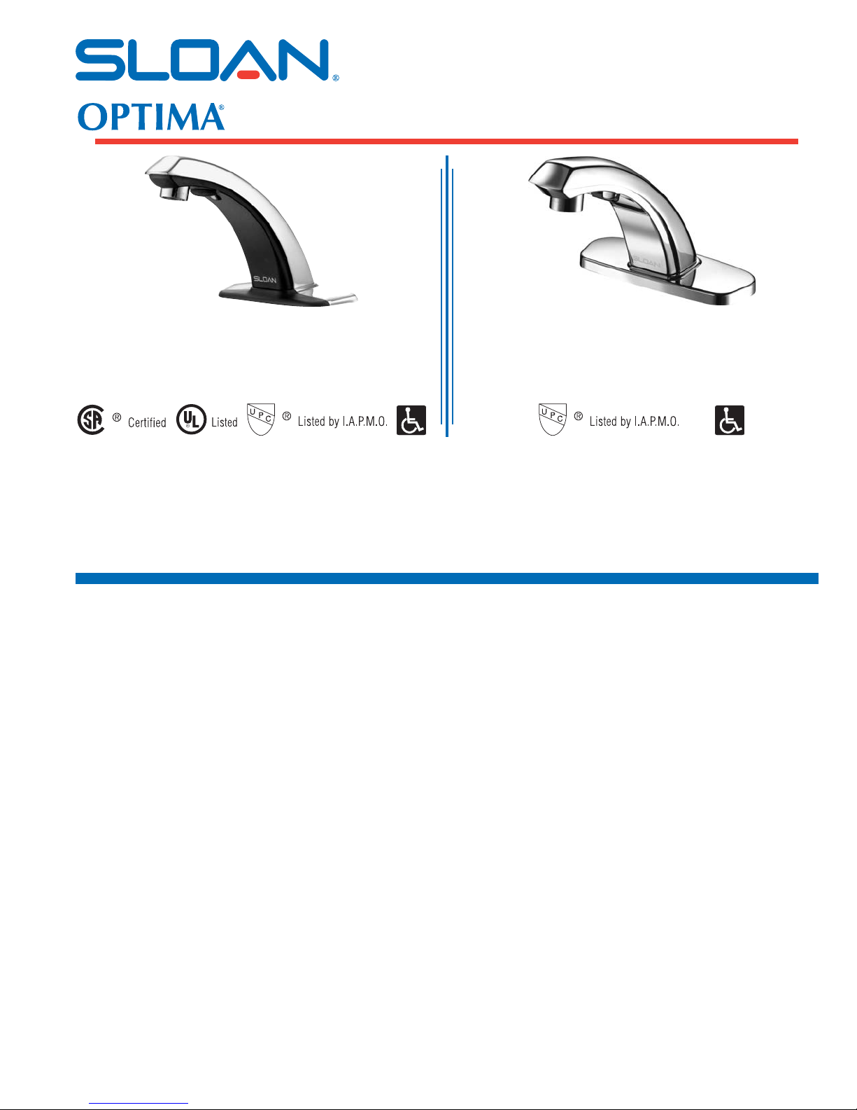
Model ETF-80
24 VAC, Sensor Activated Lavatory Faucet
Furnished with a Black Plastic Throat Plate
Model ETF-880
24 VAC, Sensor Activated Lavatory Faucet
Furnished with a Chrome Plated Metal Throat Plate
Compliant to: ASME A112.18.1 and CSA B125.1 Compliant to: ASME A112.18.1 and CSA B125.1

2
FAUCET ROUGH-IN
ETF-80 Faucet with Bak-Chek®Tee
for Hot and Cold Water Supply
(shown with 4” trim plate)
ETF-80 Faucet with ADM Variation Mixing Valve
for Hot and Cold Water Supply
(shown with 8” trim plate)
ETF-80 Faucet with BDM and BDT Variation
Mixing Valves for Hot and Cold Water Supply
(shown with 4” trim plate)
ETF-880 Faucet with Bak-Chek®Tee
for Hot and Cold Water Supply
(shown with 4” trim plate)
ETF-880 Faucet with ADM Variation Mixing Valve
for Hot and Cold Water Supply
(shown with 8” trim plate)
ETF-880 Faucet with BDM and BDT Variation
Mixing Valves for Hot and Cold Water Supply
(shown with 4” trim plate)
ETF-80 Faucet ETF-880 Faucet
3
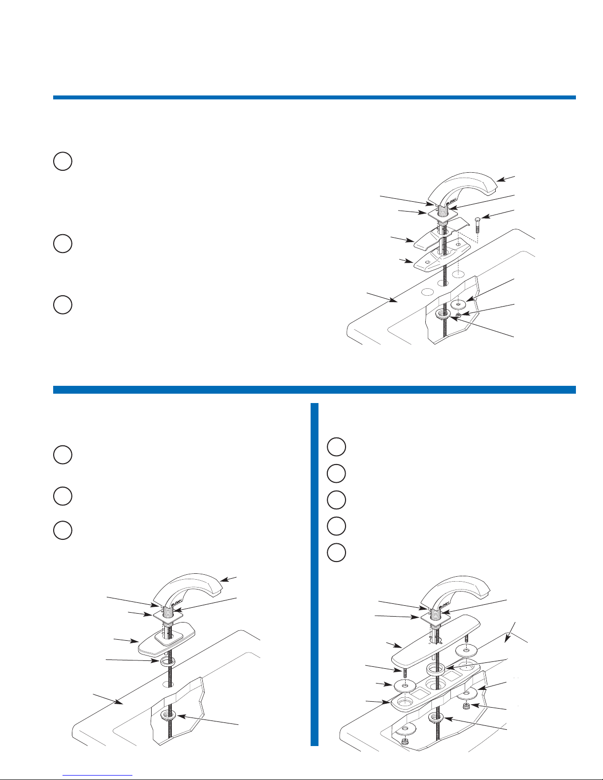
1A ETF-295-A (for ETF-80) Single
Hole 4” Trim Plate
ASlide Rubber Faucet Gasket onto Faucet Shank. Ensure that Roll
Pin on base of Faucet fits into hole in Rubber Faucet Gasket.
Note: When installing with a Sloan Mixing Valve, install Faucet and Trim Plate before installing Mixing Valve. For complete installation guidelines, refer to
the Installation Instructions supplied with the Sloan mixing valve.
BInsert Hex Bolts into Black Plastic Base Plate (if sink has only a
center hole, see note above). Place Chrome Cover Plate over
Black Plastic Base Plate. Slide Trim Plate assembly onto Faucet
Shank. Align Roll Pin with small hole in Trim Plate assembly.
Note: If Trim Plate is used on a sink with a center hole only, Trim Plate
Bolts are not used. Apply plumber’s putty to underside of Trim Plate to
prevent Faucet from rotating.
CInsert Trim Plate Bolts through the 4 inch (102 mm) spread deck
holes and Faucet Shank through the 1 inch (25 mm) minimum
diameter deck hole. Secure Trim Plate to Deck using the large
Plate Washers and Hex Nuts supplied. Secure Faucet from below
Deck using the Flange Nut supplied.
ROLL PIN
RUBBER
FAUCET GASKET
COVER PLATE
BLACK PLASTIC
BASE PLATE
DECK
FAUCET SHANK
TRIM PLATE
HEX BOLTS (2)
PLATE
WASHERS (2)
HEX NUTS (2)
FLANGE NUT
1Install Faucet Spout and Trim Plate — Refer to the appropriate step (1A-1C) for
your application.
1BETF-662-A (for ETF-880) Single
Hole 4” Trim Plate
ASlide Rubber Faucet Gasket onto Faucet Shank. Ensure that Roll
Pin on base of Faucet fits into hole in Rubber Faucet Gasket.
BSlide Trim Plate and Back-up Spacer onto Faucet Shank. Align Roll
Pin with small slot in Trim Plate.
CSecure Faucet from below Deck using the Flange Nut supplied.
ROLL PIN
RUBBER FAUCET
GASKET
TRIM PLATE
BACK-UP
SPACER
DECK
FAUCET SHANK
FLANGE NUT
1CETF-510-A (for ETF-80/880) Single
Hole 8” Trim Plate
ASlide Rubber Faucet Gasket onto Faucet Shank. Ensure that Roll
Pin on base of Faucet fits into hole in Rubber Faucet Gasket.
BSlide Trim Plate and Back-up Spacer onto Faucet Shank. Align Roll
Pin with small slot in Trim Plate.
CSlide Washer Gaskets over Studs. Place Studs and Faucet Shank
through Base Gasket and holes in Deck.
DSecure Trim Plate from below Deck using the two (2) Fender
Washers and two (2) Finger Nuts supplied.
ESecure Faucet from below Deck using the Flange Nut supplied.
ROLL PIN
RUBBER
FAUCET
GASKET
TRIM PLATE
STUD
DECK
FAUCET SHANK
WASHER
GASKET (2)
BASE
GASKET
BACK-UP
SPACER
FENDER
WASHER (2)
FINGER NUT (2)
FLANGE NUT
ETF-880 FAUCET
ETF-80 FAUCET
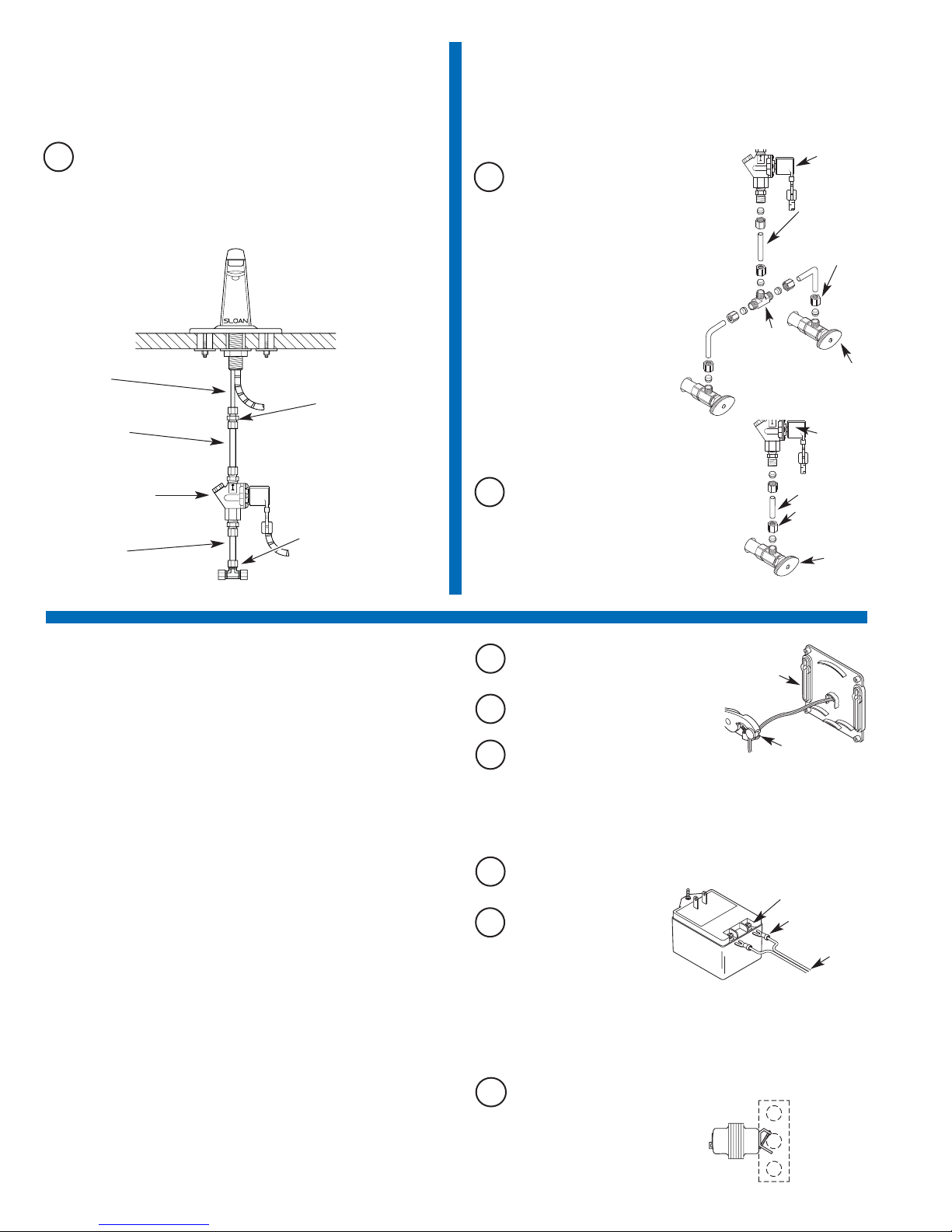
2Install Solenoid Valve
A
Note: Flow direction of Solenoid Valve is indicated by an arrow on the
Valve Body.
Install the 1/4 inch end of the 1/4 to 3/8 inch Compression Fitting
onto the Spout’s copper Supply Tube. Connect 3/8 inch O.D.
Supply Tube between Compression Connection on Solenoid Valve
and Compression Fitting on Spout’s copper Supply Tube.
4Install Transformer
Multiple Faucets
Multiple faucets can be powered by a single transformer that has been
properly sized. Allow a minimum of 15 VA of current rating for each
solenoid valve used. Refer to the following example to determine the
required current rating for 3 OPTIMA faucets.
Example:
Total number of OPTIMA faucets: 3
Total number of solenoid valves: 3
Multiply by current rating: 15 VA
——
Minimum current rating of required transformer: 45 VA
Transformers Available with the ETF-80 and ETF-880 Faucets
Standard Plug-In † ETF-233 120 VAC 35 VA
Standard Box Mount EL-248-40 120 VAC 40 VA
† In Canada, use ETF-416 (120 VAC, 35 VA).
Optional Transformers Available from Sloan
Box Mount EL-154 120 VAC 50 VA
Foot Mount EL-208 120 VAC 100 VA
Box Mount EL-342 240 VAC 50 VA
All Sloan transformers are 50/60 Hz.
Other transformers (not supplied by Sloan) may be used provided they
meet UL requirements for Class 2 transformers.
PLUG-IN TRANSFORMERS
Important: DO NOT plug Transformer into receptacle until all wiring has
been completed. The Transformer is supplied with a 10 foot Cable;
however, this Cable can and should be shortened to meet installation
requirements.
AStrip ends of Transformer Power Cable
approx. 3/16 to 1/4 inch (5 to 6 mm).
EInstall Crimp Connectors and
connect Power Cable ends to
Transformer Terminals.
DConnect Power Cable to Terminal Block on Connector Board. See
Step 6.
CInsert Power Cable and Strain Relief into
hole at back of Control Module. Install right angle Strain Relief so
that Power Cable enters the Control Module from the bottom.
BInstall Strain Relief 3 inches (76 mm)
from one end of Power Cable.
BOX MOUNT TRANSFORMER
Important: DO NOT supply power to primary side of Transformer until
wiring is completed.
Mount Transformer on a metal electrical junction box (supplied by others). (“J”
box should be mounted inside chase wall or above ceiling.) Install Transformer
within 50 feet (15.24 meters) of Faucet. 18 gauge wire is recommended.
ARun wires from secondary side
of Transformer to 3/8 inch (10
mm) hole at back of Control
Module Enclosure. If necessary,
wires can be run through wall and
then inserted through hole in back of
Control Module Enclosure.
CONTROL
MODULE
BASE
POWER CABLE
STRAIN
RELIEF
CRIMP
CONNECTORS
TRANSFORMER TERMINALS
24 VAC
SECONDARY 120 VAC
PRIMARY
BOX MOUNT
TRANSFORMER
(EL-248-40
SHOWN)
3Connect Supply Line(s) from
Supply Stop to Solenoid Valve Inlet
For Dual Line Hot and Cold Water
Supply Applications
Install a 3/8 inch (10 mm) copper supply
tube between Bak-Chek®Compression Tee
and hot and cold supply stops. (Supply
stops and copper supply tube furnished by
installer.) Install a 3/8 inch (10 mm) copper
supply tube between Bak-Chek®
Compression Tee and inlet side of
Solenoid Valve. Tighten
Compression Fittings securely.
Note: Failure to install the Bak-Chek®Tee
can result in a cross flow connection
when the faucet is off and the supply
stops are open. If pressure of the hot
and cold water supply differ, hot water
can migrate into the cold water supply or
vice-versa. Most plumbing codes require that
the Bak-Chek®be used to prevent this.
3/8” (10 mm)
BAK-CHEK®TEE
USED ON DUAL
WATER SUPPLY
APPLICATIONS
ONLY
3/8” (10 mm)
COMPRESSION
FITTING
3/8” (10 mm)
SUPPLY TUBE
SOLENOID
VALVE
SUPPLY
STOP
A
3/8” (10 mm)
COMPRESSION
FITTING
3/8” (10 mm)
SUPPLY TUBE
SOLENOID
VALVE
SUPPLY
STOP
BFor Single Line Water Supply Applications
Install a 3/8 inch (10 mm) copper supply tube
between the supply stop and inlet side of
Solenoid Valve. (Supply stop and copper
supply tube furnished by installer.) Tighten
Compression Fittings securely.
Important: Keep thread sealant out of your waterway and prevent
component part damage! Do not use sealant on compression fittings.
When thread sealant is used, do not apply it to the first two “starter”
threads.
4
COPPER
SUPPLY
TUBE
3/8” SUPPLY
TUBE (NOT
SUPPLIED)
1/4 TO 3/8 INCH
COMPRESSION
FITTING
SOLENOID VALVE
3/8” (10 mm)
BAK-CHEK®
COMPRESSION
TEE
3/8” SUPPLY
TUBE (NOT
SUPPLIED)
Important: Flush dirt, debris, and sediment from the supply line(s).
Important: Twist stranded ends of Power Cable before inserting into
Terminal Block. Fraying of Stranded Power Cable Wire can cause a short
and damage the Control Module and Transformer when powered.

5
5Mount Control Module to Wall
EXTENSION CABLES
Extension Cables are available as an option from Sloan to allow for
installing the Control Module remote from the Faucet Spout and Solenoid
Valve. Refer to the Parts List for available lengths.
BMount Control Module to wall using Mounting Screws and Plastic
Anchors.
AInstall the Control Module in an appropriate location as shown in
Rough-in. Control Module must be installed so that all cables
enter from the bottom of the unit. When installed, Cables from the
Spout and Solenoid Valve to the Control Module should have
some slack.
4” (102 mm)
6Control Module Connections
BInsert Solenoid Valve Connector into the Modular Receptacle on
Connector Board.
CInsert Locking Connector from Faucet Spout into mating
Receptacle on Connector Board. Allow 3 to 4 inches (76 to 102
mm) of Cable to extend into the Control Module.
DInsert each Conduit Cable into a strain relief slot in the Control
Module.
ARoute Cables from Solenoid Valve and Spout to the Control
Module.
CONTROL
MODULE
ENCLOSURE
FROM SOLENOID
VALVE
FROM
TRANSFORMER
STRAIN
RELIEF
SLOTS
FROM FAUCET
SPOUT
TERMINAL BLOCK -
1. REMOVE
TERMINAL BLOCK
2. INSERT POWER
CABLES
3. SECURE WITH
SCREWS
4. REINSTALL
TERMINAL BLOCK
CONNECTOR
BOARD
POWER CABLE
MODULAR
RECEPTACLE
Plug In Transformer
APlug Transformer into 120 VAC Receptacle.
7
TRANSFORMER
8Start-Up
ASupply power to Transformer.
Note: The Control Module is equipped with two LED lights. When power
is supplied by the Transformer, one LED will illuminate green. When
Sensor is activated, this LED will change to red. A second red LED
illuminates when Solenoid Valve is activated.
BOpen Supply Stop(s). With Aerator removed, activate Faucet for
30 seconds by placing hands in front of Sensor. The Solenoid
Valve should “click” and water should flow from the Spout. If this
does not occur, refer to the Troubleshooting section of this
installation instructions.
CClose Supply Stop(s) and install Spray Head in Spout using the
Key provided. Reopen Supply Stop(s), activate Faucet and check
for leaks.
THREAD THE SPRAY
HEAD INTO OPENING
OF SPOUT
SPRAY HEAD
SPOUT
This manual suits for next models
1
Table of contents
Other Sloan Control Unit manuals

Sloan
Sloan TRUFLUSH TRF 8900-CP User manual

Sloan
Sloan G2 Optima Plus Operating manual

Sloan
Sloan Optima Plus EBV-500-A User manual

Sloan
Sloan NAVAL 110 User manual

Sloan
Sloan 152 ES-S TMO SWB User manual

Sloan
Sloan 152 ES-S TMO SWB User manual

Sloan
Sloan G2 Optima Plus Operating manual

Sloan
Sloan SOLIS 8100 Series User manual


