manuals.online logo
Brands
  1. Home
  2. •
  3. Brands
  4. •
  5. Sloan
  6. •
  7. Control Unit
  8. •
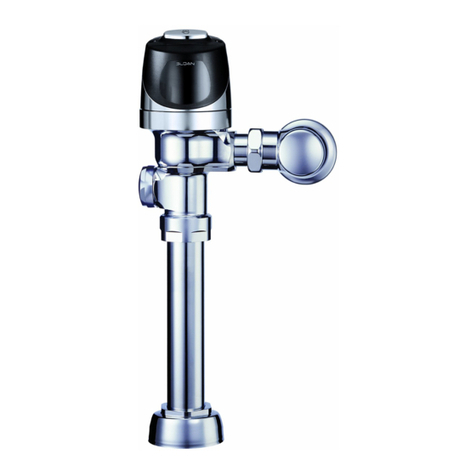
  9. Sloan TRUFLUSH TRF 8900-CP User manual

Sloan TRUFLUSH TRF 8900-CP User manual

Code No. 08160044
Rev. 1(11/21)
INSTALLATION INSTRUCTIONS FOR
TRUFLUSH ELECTRONIC DUAL FLUSH WALL PLATE
LIMITED WARRANTY
Unless otherwise noted, Sloan India Pvt. Ltd warrants this product,
manufactured and sold for commercial or industrial uses, to be free
from defects in material and workmanship for a period of five (5)
years and 1 Year- All Electronic & battery not covered in warranty
from date of first purchase. During this period, Sloan India Pvt. Ltd
will, at its option, repair, replace, or refund the purchase price of any
product which fails to conform with this warranty under normal use
and service. This shall be the sole and exclusive remedy under this
warranty. Products must be returned to Sloan India Pvt. Ltd, at
customer’s cost. No claims will be allowed for labor, transportation or
other costs. This warranty extends only
to persons or organizations who purchase Sloan India Pvt. Ltd
products directly from Sloan India Pvt. Ltd for purpose of resale. This
warranty does not cover the life of the batteries.
THERE ARE NO WARRANTIES WHICH EXTEND
BEYOND THE DESCRIPTION ON THE FACE
HEREOF. IN NO EVENT IS SLOAN INDIA PVT. LTD
RESPONSIBLE FOR ANY CONSEQUENTIAL
DAMAGES OF ANY MEASURE WHATSOEVER.
TruFlush Model:
TRF 8900-CP
PRIOR TO INSTALLATION
TOOLS REQUIRED FOR INSTALLATION
• Phillips screwdriver
This valve is designed for new construction or where there is easily
accessed plumbing for the xture and the valve.
This valve is designed for minimum six inch (152 mm) wall space
depth. Distance from center of the valve (inlet or outlet pipe) to the
nished surface of the wall can vary from 2”-3” (51-76 mm).
Wall plate opening must be of 5.6” x 5.6” (142 x 142 mm). Mud plate
is provided and must accompany valve for proper installation. Mud
plate is removed after wall is nished.
ITEMS INCLUDED WITH THE PRODUCT
ITEM #1: WALL BOX AND
ELECTRONIC VALVE
ASSEMBLY
ITEM #2: MUD GUARD
ITEM #3: ACTIVATION
ASSEMBLY TOOL
ITEM #4: #8-32 X 2" TRUSS
HEAD SCREWS
ITEM #5: 1/4-20 X 2"
SCREWS
SENSOR VALVE BOX
ITEM #1: WALL BOX
ITEM #2: WALL PLATE
ITEM #3: SENSOR ASSEMBLY
ITEM #4: ACTIVATION BUTTON
ITEM #5: BATTERY PACK
ITEM #6: 4X BATTERIES
ITEM #7: 4X #8-32 X 2"
TRUSS HEAD SCREWS
ITEM #7: 5/64" HEX KEY
WALL PLATE BOX
• Adjusting tool (supplied)
1. Wall Bracket
2. Wall Plate
3. Sensor Assembly
4. Battery Pack
5. (4) Batteries
6.(4) #8-32 x 2 Screws
7.Allen Key
8.Installation instructions
WALL PLATE BOX
1. Wall Bracket 2. Wall Plate 3.PCB Assembly
4. Battery Pack 5. (4) Batteries 6. (4) #8-32 x 2 Screws 7. Allen
Key
8. Instructions
• Flathead screwdriver .118”
(3 mm or below)
• Wire stripper tool
1. CONNECT FLUSHOMETER
2
Refer Valve Assembly Installation Manual (08160054).
2. INSTALL WALL PLATE ASSEMBLY
-
-
+
+
+
-
2. Mount the Wall Bracket to valve and secure it using the
#8-32 x 2 Screws Screws (Supplied).
3. Open the battery package (supplied) by unscrewing the lid screw, insert the
batteries (4Nos, Supplied) into the battery package as shown and close the lid by
tightening the screw.
4. Insert the battery package on right side of valve as shown.
5. Connect the battery box black connector to black connector on PCB assembly, Connect Solenoid grey connector to grey connector on PCB assembly.
NOTE: RED LED WILL START BLINKING WHEN POWER IS CONNECTED TO THE PCB ASSEMBLY
!!! ONLY FOR HARDWIRE CONNECTION !!!
5a. Using the wire stripping tool strip, the ends of the transformer wire that was routed when installing the valve.
5b. Insert wire in blue terminal block and tighten the terminal screws.
5c. Connect the terminal block to the PCB assembly as shown.
1. Remove the mudguard by unscrewing the two screws and
discard the mudguard
3
Snap clip
6. Align the 4 slots on the PCB Assembly with the mounting pegs on the Wall Bracket and slide the PCB assembly all the way down.
7. Disconnect the Solenoid Connector and lift the button as shown,
Use the tool to turn the activation assembly clockwise
(to lessen the flow) or anticlockwise (to increases the flow).
8. Reconnect the solenoid and check the flow by flushing, repeat
step 7 to adjust the flow until the flow
rate delivered properly cleanse the
fixture.
THE FLUSHOMETER IS ENGINEERED FOR QUIET OPERATION.
EXCESSIVE WATER FLOW CREATES NOISE, WHILE TOO
LITTLE WATER FLOW MAY NOT SATISFY THE NEEDS OF THE
FIXTURE. PROPER ADJUSTMENT IS MADE WHEN PLUMBING
FIXTURE IS CLEANSED AFTER EACH FLUSH WITHOUT
SPLASHING WATER OUT FROM THE LIP AND A QUIET
FLUSHING CYCLE IS ACHIEVED.
!!! IMPORTANT !!!
THE ACTIVATION ASSEMBLY SHOULD NEVER BE OPENED TO
THE POINT WHERE THE FLOW FROM THE VALVE EXCEEDS
THE FLOW CAPABILITY OF THE FIXTURE. IN THE EVENT
OF A VALVE FAILURE, THE FIXTURE MUST BE ABLE TO
ACCOMMODATE A CONTINUOUS FLOW FROM THE VALVE.
!!! IMPORTANT !!!
UNDER NO CIRCUMSTANCES SHOULD THE SOLENOID BE
REMOVED OR ADJUSTED.
!!! NOTE !!!
MAKE SURE FLUSHOMETER SOLENOID CONNECTOR IS
DISCONNECTED FROM SENSOR ASSEMBLY EVERY TIME
BEFORE ROTATING ACTIVATION ASSEMBLY.
!!! NOTE !!!
MAKE SURE SOLENOID CONNECTOR GOES THROUGH THE
CENTER OF THE ADJUSTING TOOL TO AVOID DAMAGE TO THE
CABLE.
!!! NOTE !!!
9. Make sure the retaining screw is fully tightened, slide the PCB assembly all the way
up and align the wall plate cutout with PCB assembly as shown.
10. Push the wall plate all the way in then slide the wall plate down.
11. Use the allen key (supplied) to unscrew the retaining screw until it touches the wall
plate then make sure the wall plate is completed fixed.
NOTE: DO NOT UNSCREW ANYMORE ONCE THE RETAINING SCREW
TOUCHES WALL PLATE
4
For complete listing of items available for repair, please consult Maintenance and Repair Guide.
available on www.sloan.in
© 2021 SLOAN
Code No. 08160044
Rev. 1(11/21)
Manufactured by Sloan India Pvt. Ltd, patents pending.
SLOAN INDIA PRIVATE LIMITED
344, PHASE-II UDYOG VIHAR, GURGAON 122015 Phone: (+91) 124-6013300/33
Toll Free: 1800.123.3080 | customercare@sloan.in | sloan.in | copyright © 2021 Sloan All rights reserved
CARE AND CLEANING
DO NOT use abrasive or chemical cleaners (including chlorine bleach) to clean Flushometers that may dull the luster and attack the chrome or special
decorative finishes. Use ONLY mild soap and water, then wipe dry with clean cloth or towel. While cleaning the bathroom tile, protect the Flushometer from
any splattering of cleaner. Acids and cleaning fluids will discolor or remove chrome plating.
Valve Assembly Installation Manual (08160054), available on www.sloan.in

Other Sloan Control Unit manuals

Sloan G2 Optima Plus Operating manual

Sloan

Sloan G2 Optima Plus Operating manual

Sloan NAVAL 110 User manual

Sloan

Sloan NAVAL 110 User manual

Sloan Optima Plus EBV-500-A User manual

Sloan

Sloan Optima Plus EBV-500-A User manual

Sloan SOLIS 8100 Series User manual

Sloan

Sloan SOLIS 8100 Series User manual

Sloan 152 ES-S TMO SWB User manual

Sloan

Sloan 152 ES-S TMO SWB User manual

Sloan Optima ETF-80 User manual

Sloan

Sloan Optima ETF-80 User manual

Sloan 152 ES-S TMO SWB User manual

Sloan

Sloan 152 ES-S TMO SWB User manual

Sloan G2 Optima Plus Operating manual

Sloan

Sloan G2 Optima Plus Operating manual

Popular Control Unit manuals by other brands

jbc JNA instruction manual

jbc

jbc JNA instruction manual

ETAS ES411.1 user guide

ETAS

ETAS ES411.1 user guide

Halma Ocean Optics Jaz Ferrite Installation

Halma

Halma Ocean Optics Jaz Ferrite Installation

Inner Range SkyGuard IGM Installation & operation manual

Inner Range

Inner Range SkyGuard IGM Installation & operation manual

Rockwell Automation Allen-Bradley 1784-KT2/B Installation data

Rockwell Automation

Rockwell Automation Allen-Bradley 1784-KT2/B Installation data

Advanced Axis AX-PSU-6 installation instructions

Advanced

Advanced Axis AX-PSU-6 installation instructions

Aliaxis PVC-U manual

Aliaxis

Aliaxis PVC-U manual

Arbor Technology EmQ-i2200 Quick installation guide

Arbor Technology

Arbor Technology EmQ-i2200 Quick installation guide

Girard Systems 98GCK-45DR Installation and programming guide

Girard Systems

Girard Systems 98GCK-45DR Installation and programming guide

General Photonics FPS-002 Instruction Notes

General Photonics

General Photonics FPS-002 Instruction Notes

Neumo RIEGER N1 Operating and maintenance manual

Neumo

Neumo RIEGER N1 Operating and maintenance manual

MaxStream XStream XH9-019 Series manual

MaxStream

MaxStream XStream XH9-019 Series manual

Siemens QAW910 manual

Siemens

Siemens QAW910 manual

GEA VARIVENT T R Series operating instructions

GEA

GEA VARIVENT T R Series operating instructions

Pilz PNOZ m ES Powerlink operating manual

Pilz

Pilz PNOZ m ES Powerlink operating manual

Vingtor Stentofon EAM-200 quick start guide

Vingtor Stentofon

Vingtor Stentofon EAM-200 quick start guide

LiteOn EVO6000 Series user manual

LiteOn

LiteOn EVO6000 Series user manual

unicore UM960 Installation and Operation User Manual

unicore

unicore UM960 Installation and Operation User Manual

manuals.online logo
manuals.online logoBrands
  • About & Mission
  • Contact us
  • Privacy Policy
  • Terms and Conditions

Copyright 2025 Manuals.Online. All Rights Reserved.