SMA Fimco Pro Series User manual

Page 1
Model: 800-TRL50PROBL
(5303057)
(50 Gallon Professional
Lawn & Garden Trailer Sprayer)
Assembly Instructions
Make sure the contents of the sprayers carton match the
items shown on page 2 of the manual.
Follow the steps on pages 3, 4, 5 & 6 to properly assemble
the sprayer.
Professional Grade Pump (4.0 GPM):
Ideal for Harsh Chemicals & Oil
Based Chemicals with Surfactants
Long Range 22” PRO SERIES Handgun
38’ Horizontal Spray & 27’ Vertical
Roundup® Ready
Technical Specifications
50 Gal. Corrosion-Resistant Polyethylene Tank
Pro Series 4.0 GPM, 45 PSI, 12 Volt Pump
Adjustable Height Boomless Boom (30’ Spray Coverage)
Corrosion-Resistant Nozzles
18 x 8.5 x 8 Turf Tires
Multi-Lid
OWNER’S MANUAL
General Information
Thank you for purchasing this product. The purpose of this
manual is to assist you in operating and maintaining your lawn
& garden trailer sprayer.
If you should have a question or experience a problem with
your SMA Product: call the Toll free number above.
Our technical support representatives will be happy to
help you. In most cases a customer service rep. can
resolve the problem over the phone.
To obtain prompt, efficient service, always remember to give
the following information....
• Correct Part Description and/or part number
• Model number and Serial Number
Part descriptions and numbers can be obtained from the
illustrated parts list section(s) of this manual.
BEFORE RETURNING THIS PRODUCT
FOR ANY REASON, PLEASE CALL
1-870-935-3291
Retain a copy of your receipt for your unit, as it will be required
to validate any warranty service.
Warranted against manufacturer or workmanship defects from
date of purchase with copy of receipt:
Homeowner Usage: One Year
Commercial Usage: 90 Days.
#1 Walter Kratz Drive—Jonesboro, AR 72401
Phone: 870-935-3291 : Fax: 870-935-5651
[5195202 (08/19)]

Page 2
Contents of your sprayer’s carton (800-TRL50PROBL)
Tank/Plumbing Pre-Assembly
Owner’s
Manual
Tongue
Assembly
Contents of
Parts Bag
(5281302)
Boom Mount Kit (#5281316)
“Wet Boom” Sub-Assembly
End Nozzle (5275122)
Pkg. of 2: #5275713
1” x 32”
Axle Shaft
Turf
Tires

Page 3
Your tank comes already mounted to the main frame and pre-
assembled with the pump, manifold, bypass, intake assembly,
lid, handgun, handgun hose amd handgun hose quick connect
already attached.
Assembling the tongue to the frame. Locate the (2) bent clevis
pins from the parts bag.
Slide the preassembled tongue into the receiver of the main
frame and lock in place with one bent clevis pin, securing with
the clip (See Detail A).
Insert the other bent clevis pin into the hole in the hitch and
secure with clip.
Detail A
Step 1
Locate the (2) axle spacers, (2) machine bushings,
(2) hitch pin clips and (2) turf tires.
Slide a machine bushing and axle spacer onto the
axle.
Slide the wheel onto the axle, making sure the
valve stem is facing outward.
Retain the wheel on the axle with the hitch pin
(See Detail C).
Repeat for other side.
NOTE: The wheels have grease zerks for bear-
ings. After the wheels are installed, the bearings
should be filled with a NGLI No. 2 lithium grease.
Once a year new grease should be added to each
wheel.
Step 2
Detail B
Detail C
Step 3
Locate axle, (2) 1” Axle Clamps, (4) H.H.C.S. Flanged 3/8"-16nc
x 1" bolts and (4) 3/8-16nc Hex Flanged Toplock Nuts, Gr. 5.
Loosely attach the axle clamp to the main frame using 2 bolts
and 2 nuts, do not tighten (See Detail B). Repeat for other side.
Slide the axle through the 1” axle clamp in one side of the frame
and through the corresponding hole on the
other side,
being sure to center the axle. Tighten the
bolts and nuts.
NOTE: the axle will not turn or slide once
the bolts are tight.

Page 4
• A phillips head screwdriver is required for this step
Locate the (4) #10 x 1/2” screws, (2) hose wraps and
(2) rubber grommets.
Insert the rubber grommets into the hose wraps. Place a
screw through the holes in the hose wrap and bring it up to
the tank. Secure the holders in place.
**Do Not Over-Tighten**
Wrap the hose and slip in the handgun.
Install the pressure gauge. Hand tighten securely.
** DO NOT OVER-TIGHTEN **
Step 4
Step 6
Locate the (2) boom mount brackets, (4) 5/16”-18 x
9/16” x 2-3/16” square u-bolts and (8) 5/16”-18 hex
whiz nuts.
Mount the boom mount brackets on the upright boom
arms as shown.
You can position them as needed, just be sure that
they are even with each other.
Step 5

Page 5
1. Start by sliding Items 4, 3, 2 onto the boom tube (Item 1)
as shown. First slide Item 4 on to the tube. Next slide Item 3
on to the tube, making sure the “Long” portion is facing the nozzle
end. Remove Item 2 from nozzle body and place on boom tube about
a 1/2” to 3/4” from the end of the tube.
2. Slide the (complete) end nozzle assembly onto the stainless steel boom tube,
with a somewhat “twisting” motion, so that the end face of the boom tube “butts”
up against the surface face inside the nozzle body.
3. Now push the “compression olive” (Item 3) against O-ring (Item 2) and slide
(both) into the nozzle body opening firmly.
4. Firmly tighten flynut (Item 4) onto threads of nozzle body.
Repeat for other side.
NOTE: If water is shooting back on the boom tube, item 2 is not in the correct placement.
End Nozzle Assembly Procedure
For Boomless “Wet”Boom
Your boom will come with the (2) end nozzle assemblies
NOT affixed to your boom tube. Follow the instructions
below to attach these properly to the boom tube, as
shown.
Assembled
End Nozzle
15°
End Nozzle Informaon
(5275122)
This nozzle mounng stem
Has a ratcheng moon.
** Each “click” of the ratcheng moon is approx. 15° **
For proper/opmal spray coverage,
The nozzle must be at a 15° angle
The 15° angle shown will prevent the outer
Nozzles from overlapping with the center nozzle.
“On/O” Valve Posions
Valve “Open” Valve “Closed”
Service Posion On/O Valve Knob
Eliminate line pressure, then pull out
to check diaphragm condion.
Note: The check valve & diaphragm can fall out during transport, if the
knob is not turned to the “ON” or “OFF” posion.
Step 7
Item 2 is shipped inside of
the end nozzle assembly.
Remove & place on tube.

Page 6
*** The Sprayer should now be ready for use ***
Attach the boom to the boom mount brackets with the
(2) u-bolts and (4) whiz locknuts. Make sure the u-bolts
are positioned within the grooves of the grommets on
the boom tube
NOTE: The purpose of these grommets is to prevent
metal-to-metal contact between the u-bolts, boom
tube and boom mounting brackets.
The grommets will ‘compress’ as you tighten the whiz
locknuts onto the u-bolts. Tighten just so that the boom
tube will NOT rotate within the grommets. Alternate the
tightening of the locknuts to provide even pressure on
the grommet.
**DO NOT OVER TIGHTEN the whiz locknuts, as this
may cause the boom tube to flatten slightly!
After your boom is attached, connect the feeder hose,
using (1) hose clamp.
Place the hose clamp loosely over the end of the hose.
Slip the end of the hose over the hose barb on the cen-
ter nozzle. Use a twisting motion, if necessary, to get
the hose fully onto the barb. Bring the hose clamp to the
connection point and tighten securely.
Step 8
Step 9

Page 7
Manifold Valves CLOSED
IMPORTANT: Remove tank lid and be sure the tank is clean and free of
any foreign material. Rinse tank out of any tank residue before filling with
water to test.
Testing the Sprayer
NOTE:
It is VERY important for you to test your sprayer with plain water before actual
spraying is attempted. This will enable you to check the sprayer for leaks without
the possibility of losing any expensive chemicals.
Fill the tank about 1/2 full with plain water and drive to the starting place for spraying.
When you are ready to spray, turn the boom valve to the “on” position (Detail A). This will start
solution spraying from the tips of the boom. The pressure will decrease slightly when the
boom is spraying.
Adjust the pressure by turning the “ON/OFF” valve lever on the bypass line valve (Detail B).
Make sure your pattern is sufficient. You may down-pressure the system by ‘bypassing’ solu-
tion back into the tank. This is achieved by opening the bypass valve. Regulating pressure is
done in this manner.
Read the operating instructions and initially begin spraying by closing the ‘Pressure Adjust’
valve and opening the boom line valve (Detail A). This will enable the air in the line to be elimi-
nated (purged) through all the tips, while building pressure. When everything tests all right (no
leaks and good pressure), add the desired chemicals to the mixture and water combination
and start your spraying operation. Adjust the pressure and spray as you did in the testing
procedure.
Conditions of weather and terrain must be considered when setting the sprayer. Do not spray
on windy days. Protective clothing must be worn in some cases.
Be sure to read the chemical label(s) before application!
Operation
The pumping system draws solution from the tank, through the strainer and to the pump. The
pump forces the solution under pressure to the handgun or boom nozzles.
Connect the lead wire to a fully charged 12 volt battery. You may use either a stand-alone
battery or the battery on your towing vehicle. Connect to the positive (red) terminal first, then
connect to the negative (black) terminal. Then connect the end of the lead wire to the end of
the pump. When disconnecting, disconnect the end of the pump wire from the lead wire, then
disconnect the negative (black) connection and finally the positive (red) connection. The lead
wire has an On/Off switch to activate the pump. “-” is on and “O” is off.
Fill the tank part way with water and then add the desired amount of chemical to be sprayed.
Finish filling tank to proper level. Turn the pump on and by depressing the “-” side of the rock-
er switch. The pump is equipped with a pressure switch that is pre-set at the factory to shut
the pump off when all discharges are closed.
The pump will turn back on when one of the following actions occurs:
Handgun lever is squeezed to spray the handgun.
Boom valve is opened to broadcast spray with the boom.
Bypass valve is opened to re-circulate solution back into the tank.
When spraying with either the boom or the handgun, pressure may be reduced by slowly opening the bypass valve until desired pressure is achieved.
Opening the valve decreases pressure, closing the valve increases pressure. When spraying with the boom, the proper method to set the pressure is
to open the boom valve completely and if a lower pressure is desired, then slowly open the bypass valve until that pressure is obtained.
For the safest and most efficient chemical application, you will need to calibrate your sprayer using the tip and speed charts. Once you have deter-
mined the proper speed and pressure settings, you will need to consult your chemical label for the amount of chemical to be added to the tank. Read
the entire label. Use only according to label directions.
Detail A
Detail B
Troubleshooting Leaking Elbow on Manifold:
If your manifold is leaking at the elbow connection, remove the elbow from the
manifold. Quarter turn counter clockwise and lift off.
Look inside the cap and make sure the flat washer is in place.
If washer is in place, you’ll notice a hexagon shape cutout. While holding the
elbow and cap at the same time, using an allen wrench, head of a bolt or a
standard screwdriver, something just big enough to catch the edges, give it a twist
clockwise to snug up the connection. The elbow is a two-piece interlocking
mechanism and may just be a little loose. Replace on manifold.

Page 8
Calibration
Chemical labels may show application rates in gallons per acre, gallons per
1000 square feet or gallons per 100 square feet. You will note that the tip
chart shows 2 of these rating systems. Once you know how much you are
going to spray, then determine (from the tip chart) the spraying pressure
(PSI), and the spraying speed (MPH).
Determining the proper speed of the pulling vehicle can be done by marking
off 100, 200 & 300 feet. The speed chart indicates the number of seconds it
takes to travel the distances. Set the throttle and with a running start, travel
the
distances. Adjust the throttle until you travel the distances in the number of
seconds indicated by the speed chart. Once you have reached the throttle
setting needed, mark the throttle location so you can stop and go again,
returning to the same speed.
Add water and proper amount of chemical to the tank and drive to the starting
place for spraying.
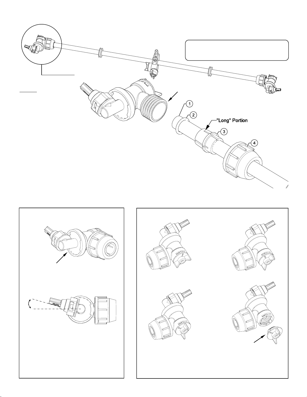
Using the Boom Nozzles
Four things must be considered before spraying with the boom.
How much chemical must be mixed in the tank.
Rate of spray (gallons per acre to be sprayed).
What pressure (p.s.i.) will be used.
Speed traveled (mph) while spraying.
Refer to the chemical label to determine your chemical mixture.
See the tip chart to determine the pressure to be used. The chart will
also show the speed used when spraying.
Start the pump and open the valve to the boom nozzles.
Check the spray pattern. Usually you can see the coverage better on a
solid concrete surface, such as a driveway.
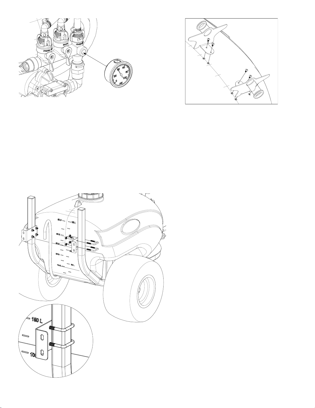
Approximate height: 33”
Maintenance During/After Spraying
Periodically check the strainer and clean the screen on your intake line.
Proper care and maintenance will prolong the life of your sprayer.
After use, drain the tank and store or dispose of chemical properly. Fill the
sprayer half way with clean water. Start the pump and allow the water to
pump through the entire plumbing system and nozzles. Drain and then refill
half full, add the recommended amount of a good quality tank cleaner, such
as FIMCO Tank Neutralizer and Cleaner. (If no tank cleaner is available, you
may substitute dish soap for this step, about 1-2 oz. per gallon). Turn pump
on and circulate through system for 15 minutes and then spray out through
boom and handgun nozzles. Refill sprayer half way with clean water and
repeat. Follow the chemical manufacturer’s disposal instructions of all wash
or rinsing water.
If boom or handgun nozzles need cleaning, remove them from the sprayer
and soak in warm soapy water. Clean with a soft bristled brush or toothpick if
necessary. Never use a metal object. Even the slightest damage can change the flow rate and spray distribution. Water rinse and dry the tips before
storing.
WARNING: Some chemicals will damage the pump valves if allowed to soak untreated for a length of time! ALWAYS flush the pump as instructed
after each use. DO NOT allow chemicals to sit in the pump for extended times of idleness. Follow the chemical manufacturer’s instructions on disposal
of all waste water from the sprayer.
NOTE: The wheels have grease zerks for bearings. Once a year new grease, a NGLI No. 2 lithium grease, should be added to each wheel.
Winter Storage
Prepare the sprayer for end-of-season storage by running RV antifreeze through the system. This will keep internal parts lubricated, protect against
corrosion and keep the unit from freezing. Note: RV antifreeze is non-toxic and biodegradable and generally safer for the environment than automotive
antifreeze.
Before storing your sprayer for winter or long term storage, thoroughly clean and drain it as much as possible. Then pour enough pink RV antifreeze
into the tank so that when the pump is turned on you can pump the antifreeze throughout the entire plumbing system, including the bypass. Make sure
to operate the boom and handgun until you see pink fluid spraying from the nozzles. Leave any remaining antifreeze in the tank. Before your next us-
age, rinse the antifreeze from the sprayer with clean water.
It is nearly impossible to drain all of the water from the sprayer and any trapped water can freeze in cold weather and damage parts of the sprayer.
Pumping the antifreeze through the system will displace the water and help prevent this damage.
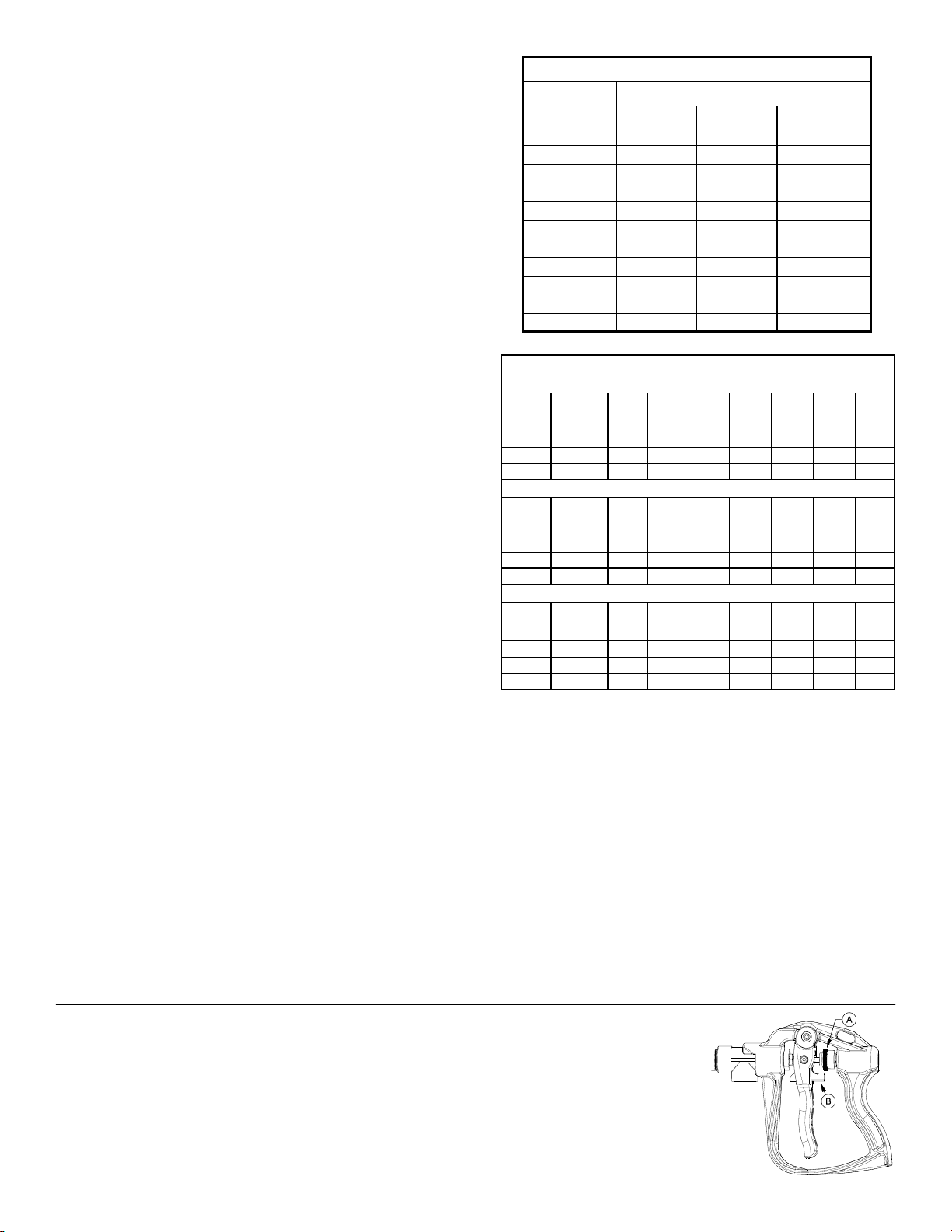
Speed Chart
Time Required in seconds to travel a distance of
Speed in M.P.H.
(Miles Per Hour) 100 Ft. 200 Ft. 300 Ft.
1.0 68 sec. 136 sec. 205 sec.
2.0 34 68 102
3.0 23 45 68
4.0 17 34 51
5.0 14 27 41
6.0 11 23 34
7.0 9.7 19 29
8.0 8.5 17 26
9.0 7.6 15 23
10.0 6.8 14 20
Rate Chart for Boomless Nozzle (Set of 3)
Gallons per Acre Based on Water - 17-1/2" Spacing
Pressure
P.S.I.
Capacity
G.P.M.
(3 Nozzles)
1 MPH 2 MPH 3 MPH 4 MPH 5 MPH 6 MPH 8 MPH
20 1.68 28.0 14.0 9.4 7.0 5.6 4.7 3.5
30 2.05 34.4 17.2 11.4 8.6 6.9 5.7 4.3
40 2.40 '39.6 19.8 13.2 9.9 7.9 6.6 5.0
Gallons per 1000 Sq. Ft. Based on Water - 17-1/2" Spacing
Pressure
P.S.I.
Capacity
G.P.M.
(3 Nozzles)
1 MPH 2 MPH 3 MPH 4 MPH 5 MPH 6 MPH 8 MPH
20 1.68 0.64 0.32 0.21 0.16 0.13 0.11 0.08
30 2.05 0.78 0.39 0.26 0.20 0.16 0.13 0.10
40 2.40 0.90 0.45 0.30 0.23 0.18 0.15 0.12
Gallons per 100 Sq. Ft. Based on Water - 17-1/2" Spacing
Pressure
P.S.I.
Capacity
G.P.M.
(3 Nozzles)
1 MPH 2 MPH 3 MPH 4 MPH 5 MPH 6 MPH 8 MPH
20 1.68 0.064 0.032 0.021 0.016 0.013 0.011 0.008
30 2.05 0.078 0.039 0.026 0.020 0.016 0.013 0.010
40 2.40 0.090 0.045 0.030 0.023 0.018 0.015 0.012
** The rate of spray as shown in the chart will remain the same with 1, 2 or 3 Nozzles **
The only difference will be with the width of the spray swath
Long Range Pro Series Handgun
• No Drip Shut O • Easy Pull Trigger Handle • Chemical Resistant Construcon
• 38’ Horizontal Throw & 27’ Vercal Throw
To adjust the spray pattern, the nut needs to be adjusted (Ref. A). Spinning it off, towards the lever, will make a cone
pattern and spinning it on, away from the lever, will make a stream. The lever (Ref. B), is the lock that can be used to lock
the lever when pulled, holding the valve open. Squeezing the trigger, will release the lock.

Page 9
Troubleshooting the Pump:
Motor does not run:
Check for loose wiring connection(s).
Make sure the 'ON/OFF' switch in the lead wire assem-
bly is in the 'ON' position. “I" is the 'ON' position and 'O'
is the 'OFF' position.
Check for defective pressure switch. Make sure you are
connected to a good 12 volt power source. Make sure
any on/off switches are in the 'on' position.
Remove the cap to the pressure switch. Pull both red
wires off of their terminals, and touch the two ends to-
gether. If your pump runs when you do this, your pres-
sure switch will need to be replaced.
Check the fuse.
Check for low voltage at the power supply.
Pump does not prime:
Check for air leaks in supply line.
Check for debris in the check valve assembly.
Check for defective check valve.
Check for clogged strainer/filter.
Check for cracks in the pump housing.
Check for empty product supply.
DO
Clean and rinse your pump after each use with Fimco Tank
Neutralizer
Winterize your pump or sprayer by rinsing, draining and
running RV Antifreeze through it before storing for the winter.
Use clean water for your spray mixture
Store inside a building when not in use.
DON’T
Pulsating flow (surging):
Check for defective pressure switch.
Check for leaks in the discharge line.
Check for restriction in the discharge line.
Check for debris in nozzle orifice.
Discharge hose may be too long.
Check for clogged strainer.
Motor continues to run after discharge is shut off:
Check for empty product supply.
Check for open bypass valve. (if equipped)
Check for low voltage.
Check for leak in discharge line.
Check for defective or dirty check valve.
Check for defective pressure switch.
Use to pump bleach.
Use with Flammable or Combustible Liquids
Store Flammable or Combustible Liquids
Leave your pump sit with spray mixture in it for extended
periods
Use dirty or unfiltered water for spraying
4.0 GPM Pump
Model: 5151073
Available Replacement Parts
1
2
3
4
5
6
Ref. # Mfg. # Description
1 94-230-55 Switch Assembly
2 94-237-05 Check Valve Assembly
3 94-231-30 Upper Housing
4 94-232-05 Valve Assembly
5 94-238-21 Drive Assembly

Page 10
Exploded View
800-TRL50PROBL
(5303057)
(See Next Page for Parts List)
See
Plumbing Detail
Next Page
See
Boom Assembly
& Parts List
Page 12
Bulkhead Fings

Page 11
This sprayer comes with an On/
Off (shut-off) valve located just
before the strainer. You must
make sure the valve is in the
“open” position before using your
sprayer.
Manifold
Detail
Plumbing
Detail
Intake Assembly
Parts List: 800-TRL50PROBL (5303057)

Page 12
Boomless “Wet” Boom Assembly
Exploded View/Parts List
(5275260)
Center Nozzle
Assembly
5275123
Boom
Sub-Assembly
5275712
End Nozzle Assembly
5275122

Page 13
NOTES:

Page 14
LIMITED WARRANTY FOR NEW FIMCO, IND. EQUIPMENT
WHO MAY USE THIS LIMITED WARRANTY. This limited warranty (the “Limited Warranty”) is provided by Fimco, Ind. to the original purchaser
(“you”) of the Equipment (as dened below) from Fimco, Ind. or one of Fimco, Ind.’s authorized dealers. This Limited Warranty does not apply to
any subsequent owner or other transferee of the Equipment. THIS LIMITED WARRANTY GIVES YOU SPECIFIC LEGAL RIGHTS, AND YOU MAY ALSO
HAVE OTHER RIGHTS WHICH VARY FROM STATE TO STATE.
WHAT THIS LIMITED WARRANTY COVERS AND FOR HOW LONG. Fimco, Ind. warrants that any new Equipment will be free from defects in
material and workmanship for a period of one (1) year (homeowner), 90 days (commercial user), aer delivery of the Equipment to you (the
“Warranty Period”). The Warranty Period is not extended if Fimco, Ind. repairs or replaces the Equipment.
WHAT IS NOT COVERED BY THIS LIMITED WARRANTY. This Limited Warranty does not apply to: (1) used Equipment; (2) any Equipment that has
been altered, changed, repaired or treated since its delivery to you, other than by Fimco, Ind. or its authorized dealers; (3) damage or deprecia-
on due to normal wear and tear; (4) defects or damage due to failure to follow Fimco, Ind.’s operator’s manual, specicaons or other wrien
instrucons, or improper storage, operaon, maintenance, applicaon or installaon of parts; (5) defects or damage due to misuse, accident or
neglect, “acts of God” or other events beyond Fimco, Ind.’s reasonable control; (6) accessories, aachments, tools or parts that were not manu-
factured by Fimco, Ind., whether or not sold or operated with the Equipment; or (7) rubber parts, such as res, hoses and grommets.
HOW TO OBTAIN WARRANTY SERVICE. To obtain warranty service under this Limited Warranty, you must (1) provide wrien noce to Fimco,
Ind. of the defect during the Warranty Period and within thirty (30) days aer the defect becomes apparent or the repair becomes necessary, at
the following address: Fimco, Ind., 1000 Fimco Lane, North Sioux City, SD 57049; and (2) make the Equipment available to Fimco, Ind. or an
authorized dealer within a reasonable period of me. For more informaon about this Limited Warranty, please call: 800-831-0027.
WHAT REMEDIES ARE AVAILABLE UNDER THIS LIMITED WARRANTY. If the condions set forth above are fullled and the Equipment or any part
thereof is found to be defecve, Fimco, Ind. shall, at its own cost, and at its opon, either repair or replace the defecve Equipment or part.
Fimco, Ind. will pay for shipping and handling fees to return the repaired or replacement Equipment or part to you.
LIMITATION OF IMPLIED WARRANTIES AND OTHER REMEDIES. THE REMEDIES DESCRIBED ABOVE ARE YOUR SOLE AND EXCLUSIVE REMEDIES,
AND FIMCO, IND.’S SOLE LIABILITY, FOR ANY BREACH OF THIS LIMITED WARRANTY. TO THE EXTENT APPLICABLE, ANY IMPLIED WARRANTIES,
INCLUDING, WITHOUT LIMITATION, THE IMPLIED WARRANTIES OF MERCHANTABILITY AND FITNESS FOR A PARTICULAR PURPOSE, SHALL BE LIM-
ITED IN DURATION TO THE WARRANTY PERIOD, AND THE REMEDIES AVAILABLE FOR BREACH THEREOF SHALL BE LIMITED TO THE REMEDIES
AVAILABLE UNDER THIS EXPRESS LIMITED WARRANTY. SOME STATES DO NOT ALLOW LIMITATIONS ON HOW LONG AN IMPLIED WARRANTY
LASTS, SO THE ABOVE LIMITATION MAY NOT APPLY TO YOU. IN NO EVENT SHALL FIMCO, IND.’S LIABILITY UNDER THIS LIMITED WARRANTY EX-
CEED THE ACTUAL AMOUNT PAID BY YOU FOR THE DEFECTIVE EQUIPMENT, NOR SHALL FIMCO, IND. BE LIABLE, UNDER ANY CIRCUMSTANCES,
FOR ANY CONSEQUENTIAL, INCIDENTAL, SPECIAL OR PUNITIVE DAMAGES OR LOSSES, WHETHER DIRECT OR INDIRECT. SOME STATES DO NOT
ALLOW THE EXCLUSION OR LIMITATION OF INCIDENTAL OR CONSEQUENTIAL DAMAGES, SO THE ABOVE LIMITATION OR EXCLUSION MAY NOT
APPLY TO YOU.
Warranty
This manual suits for next models
2
Table of contents
Other SMA Paint Sprayer manuals