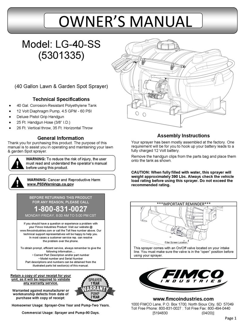
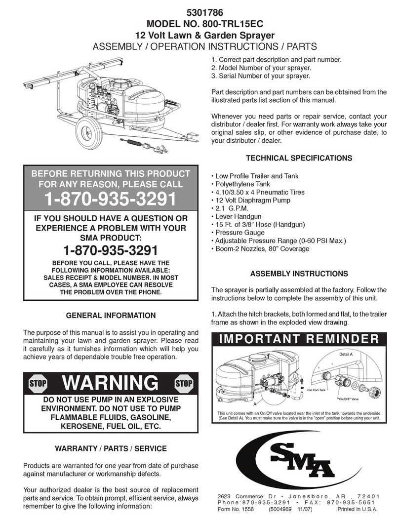
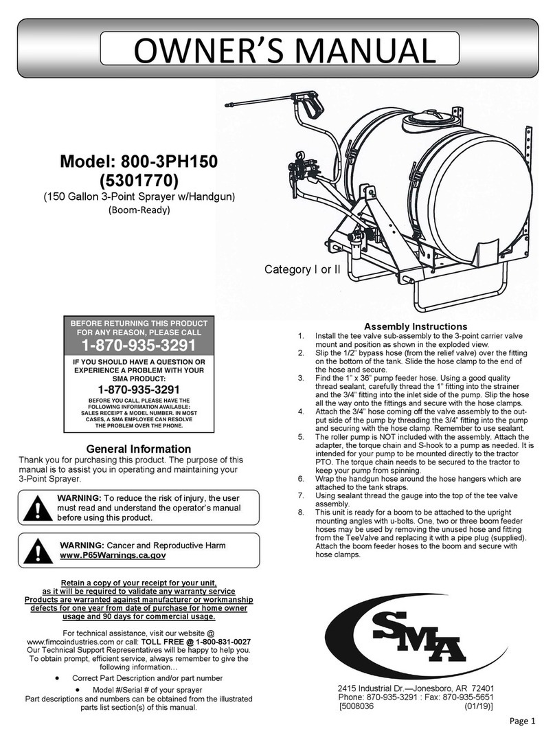
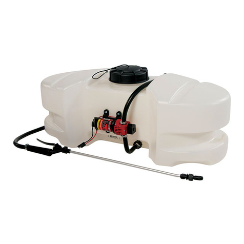
SMA 800-B10 User manual

Page 1
General Information
Thank you for purchasing this product. The purpose of this
manual is to assist you in operating and maintaining your
boom kit assembly.
Retain a copy of your receipt for your unit,
as it will be required to validate any warranty service
Products are warranted against manufacturer or workmanship
defects for one year from date of purchase for home owner
usage and 90 days for commercial usage.
For technical assistance, call: TOLL FREE @ 1-870-935-3291
Our Technical Support Representatives will be happy to help you.
To obtain prompt, efficient service, always remember to give the
following information…
Correct Part Description and/or part number
Model #/Serial # of your sprayer
Part descriptions and numbers can be obtained from the illustrated
parts list section(s) of this manual.
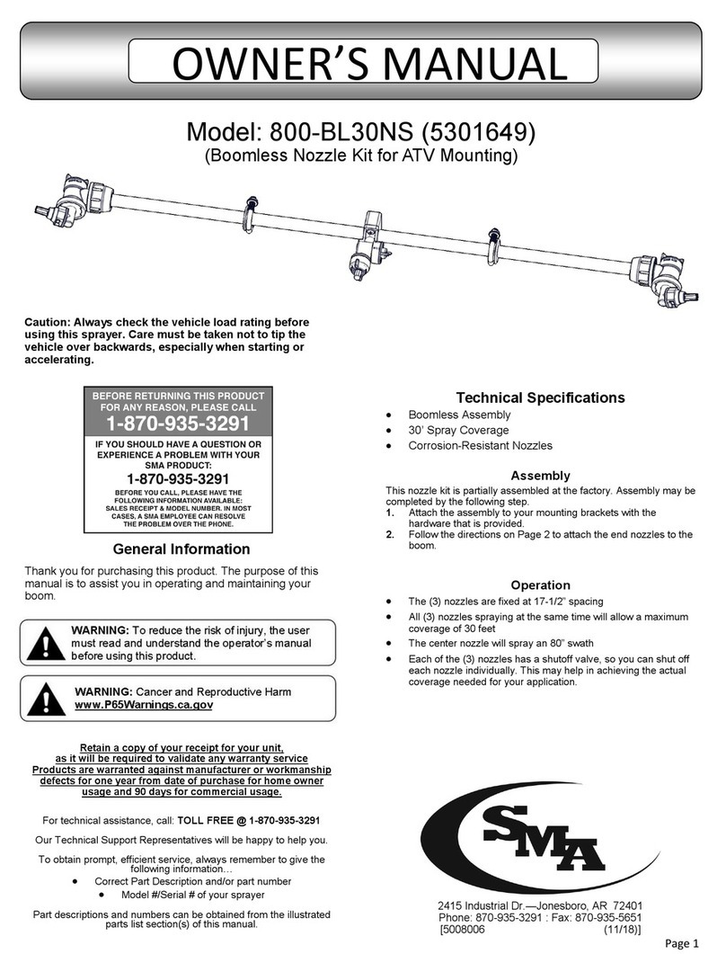
Model: 800-B10 (5301595)
(7-Nozzle Boom Assembly)
Technical Specifications
7-Nozzle Boom Assembly
Break-Away Outer Booms
140” of Spray Coverage
AIXR11002 VP, #2 (Yellow) 110° tips (**)
Check Valve Strainers, 50 Mesh, 5 PSI
(**) These tips provide excellent chemical and acid resistance, with
an exceptionally long wear life.
110° wide, tapered flat spray angle with air induction technology for
better drift management.
Compact size to prevent tip damage.
These teejet tips produce large air-filled drops through a venture air
aspirator. Assembly Instructions
Remove the parts to the boom assembly from the carton.
Refer to the parts list and exploded view drawing to help
identify all the components.
1. Center the center section of the boom onto your boom
mounts and secure in place with the hardware provided.
Be sure that the outer booms will fold ‘backwards’. The
boom should be a minimum of 18” above the ground.
2. Attach the nozzle harness assembly to the boom. The
end boom members should fold towards the rear of the
sprayer.
3. Route your boom feeder hose (not included) under the
unit, to the back end of the sprayer. Join the hose to the
‘cross fitting’. Then clamp in place with a hose clamp.
CAUTION: Never use a metal object or other sharp item for
cleaning a nozzle tip. It is better to use a nozzle brush (NOT
wire brush) or compressed air for tip cleaning.
2415 Industrial Dr.—Jonesboro, AR 72401
Phone: 870-935-3291 : Fax: 870-935-5651
[5008002 (11/18)]
OWNER’S MANUAL

Page 2
Testing the Sprayer
NOTE: It is VERY important for to test your sprayer with plain water
before actual spraying is attempted. This will enable you to check for
leaks without the possibility of losing any expensive chemicals.
Fill the tank about 1/2 full with plain water. When you are ready to
spray, turn the boom valve to the “on” position. This will start solution
spraying from the tips of the boom. The pressure will decrease slightly
when the boom is spraying. Adjust the pressure by turning the “ON/
OFF” valve lever on the bypass line valve. Make sure your pattern is
sufficient. You may down-pressure the system by ‘bypassing’ solution
back into the tank. This is achieved by opening the bypass valve.
Regulating pressure is done in this manner.
Read the operating instructions and initially begin spraying by closing
the ‘bypass’ valve and opening the boom line valve. This will enable
the air in the line to be eliminated (purged) through all the tips, while
building pressure. When everything tests all right (no leaks and good
pressure), add the desired chemicals to the mixture and water
combination and start your spraying operation.
Conditions of weather and terrain must be considered when setting the
sprayer. Do not spray on windy days. Protective clothing must be worn
in some cases
Be sure to read the chemical label(s) before application!
Calibration
Chemical labels may show application rates in gallons per acre,
gallons per 1000 square feet or gallons per 100 square feet. You will
note that the tip chart on the cover shows 2 of these rating systems.
Once you know how much you are going to spray, then determine
(from the tip chart) the spraying pressure (PSI), and the spraying speed
(MPH).
Determining the proper speed of the pulling vehicle can be done by
marking off 100, 200 & 300 feet. The speed chart indicates the number
of seconds it takes to travel the distances. Set the throttle and with a
running start, travel the distances. Adjust the throttle until you travel the
distances in the number of seconds indicated by the speed chart. Once
you have reached the throttle setting needed, mark the throttle location
so you can stop and go again, returning to the same speed.
Add water and proper amount of chemical to the tank and drive to the
starting place for spraying.
Using the Boom Nozzles
Four things must be considered before spraying with the boom.
How much chemical must be mixed in the tank.
Rate of spray (gallons per acre to be sprayed).
What pressure (p.s.i.) will be used.
Speed traveled (mph) while spraying.
Refer to the chemical label to determine your chemical mixture
See the tip chart to determine the pressure to be used. The chart
will also show the speed used when spraying.
Start the pump and open the valve to the boom nozzles.
Check the spray pattern. Usually you can see the coverage better
on a solid concrete surface, such as a driveway.
Raise or lower the nozzles so that you will have a good coverage
pattern. Generally the proper height will be about 18 inches from
the object(s) being sprayed.
Operation
Always fill the tank 1/2 full with water first and then add the chemical
slowly, mixing as you pour the chemical into the tank and then fill the
rest of the way. You may use the bypass in order to mix the chemical
and water.
The pumping system draws solution from the tank, through the
strainer/filter and to the pump. The pump forces the solution under
pressure to the handgun and/or boom nozzles.
Activate the handgun by squeezing the handle lever
Rotating the adjustable nozzle tip on the handgun will change
the tip pattern from a straight stream to a cone pattern (fine
mist)
The nozzles on the boom will spray a 140 inch wide swath. However,
it is necessary to overlap patterns 30% to get proper coverage. The
first pass will only cover a 112 inch wide swath, but each pass
thereafter will provide a 140 inch swath of proper coverage. The
proper nozzle height should be a minimum of 18 inches above the
object being sprayed. Check the nozzle pattern by spraying water on
a concrete surface. Raise the boom to a higher mounting position to
get more spray pattern overlap, if desired.
Adjusting Pressure
When the bypass valve is closed, pressure is at the highest
point.
Opening the valve will decrease pressure.
Maintenance During/After Spraying
After use, fill the sprayer tank part way with water. Start the sprayer
and allow the clear water to be pumped through the plumbing system
and out through the spray nozzles. Refill the tank about half full with
plain water and use FIMCO Tank Neutralizer and Cleaner and repeat
cleaning instructions above. Flush the entire sprayer with the
neutralizing/cleaning agent, then flush out one more time with plain
water. Follow the chemical manufacturer’s disposal instructions of all
wash or rinsing water. Remove the tips and screens from the nozzle
assemblies. Wash these items out thoroughly. Blow the orifice clean
and dry. If the orifice remains clogged, clean it with a fine bristle
(NOT WIRE) brush or with a toothpick. Do not damage the orifice.
Water rinse and dry the tips before storing.
WARNING: Some chemicals will damage the pump valves if
allowed to soak untreated for a length of time! ALWAYS flush the
pump as instructed after each use. DO NOT allow chemicals to sit in
the pump for extended times of idleness. Follow the chemical
manufacturer’s instructions on disposal of all waste water from the
sprayer.
Winter Storage
Prepare the sprayer for end-of-season storage by running RV
antifreeze through the system. This will keep internal parts
lubricated, protect against corrosion and keep the unit from freezing.
Note: RV antifreeze is non-toxic and biodegradable and generally
safer for the environment than automotive antifreeze.
Before storing your sprayer for winter or long term storage,
thoroughly clean and drain it as much as possible. Then pour
enough pink RV antifreeze into the tank so that when the pump is
turned on you can pump the antifreeze throughout the entire
plumbing system, including the bypass. Make sure to operate the
boom and handgun until you see pink fluid spraying from the
nozzles. Leave any remaining antifreeze in the tank. Before your
next usage, rinse the antifreeze from the sprayer with clean water.
It is nearly impossible to drain all of the water from the sprayer and
any trapped water can freeze in cold weather and damage parts of
the sprayer. Pumping the antifreeze through the system will displace
the water and help prevent this damage.
1
MPH
2
MPH
3
MPH
4
MPH
5
MPH
6
MPH
8
MPH
10
MPH
15 .12 35.6 17.8 11.8 8.9 7.1 5.9 4.5 3.6
20 .14 41.6 20.8 13.8 10.4 8.3 6.9 5.2 4.2
30 .17 50.4 25.2 16.8 12.6 10.1 8.4 6.3 5.0
40 .20 59.6 29.8 19.8 14.9 11.9 9.9 7.4 5.9
1
MPH
2
MPH
3
MPH
4
MPH
5
MPH
6
MPH
8
MPH
8
MPH
15 .12 .41 .27 .20 .16
20 .14 .48 .32 .24 .19
30 .17 .58 .39 .29 .23
40 .20 .68 .45 .34 .27
AIXR11002VP
AIXR11002VP
Tip
No.
Pressure
(psi)
Capacity
(GPM)
Gallons Per 1000 Sq. Ft. - Based on Water
Spray Tip Rate Chart (20" Spacing)
Tip
No.
Pressure
(psi)
Capacity
(GPM)
Gallons Per Acre - Based on Water
Speed in M.P.H.
(Miles Per Hour)
100 Ft. 200 Ft. 300 Ft.
1.0 68 sec.
2.0 34 68 102
3.0 23 45 68
4.0 17 34 51
5.0 14 27 41
6.0 11 23 34
7.0 9.7 19 29
8.0 8.5 17 26
Speed Chart
Time Required in seconds to travel a distance of

Page 3
Exploded View/Parts List:
800-B10 (5301595)
Opposite side has typical hardware setup
Elbow Tee Cross
Clamp
Bag of 7: 5277730
DETAIL Hinge
(2xs)
#5277926 1/2” to 3/8” Conversion Kit
If your existing sprayer has a 1/2” I.D. hose supplying your original boom and you now have a boom with
3/8” I.D. hose, this conversion kit allows you to easily convert your supply line to fit onto the 3/8” I.D. hose
of your new boom.
Slip the hose mender’s 1/2” barb (larger side) into your existing 1/2” feeder hose and clamp in place with
(existing) original hose clamp. Slip the (included) 3/8” hose (5-1/2” long) onto the 3/8” barb of the hose
mender and clamp in place with one of the supplied hose clamps.
Now attach the open end of the hose onto the fitting on your boom which accepts the feeder line hose.
Make sure you place the hose clamp onto that hose prior to attaching it to your boom.

Page 4
LIMITED WARRANTY FOR NEW FIMCO, IND. EQUIPMENT
WHO MAY USE THIS LIMITED WARRANTY. This limited warranty (the “Limited Warranty”) is provided by Fimco, Ind. to the original purchaser
(“you”) of the Equipment (as dened below) from Fimco, Ind. or one of Fimco, Ind.’s authorized dealers. This Limited Warranty does not apply to
any subsequent owner or other transferee of the Equipment. THIS LIMITED WARRANTY GIVES YOU SPECIFIC LEGAL RIGHTS, AND YOU MAY ALSO
HAVE OTHER RIGHTS WHICH VARY FROM STATE TO STATE.
WHAT THIS LIMITED WARRANTY COVERS AND FOR HOW LONG. Fimco, Ind. warrants that any new Equipment will be free from defects in
material and workmanship for a period of one (1) year aer delivery of the Equipment to you (the “Warranty Period”). The Warranty Period is not
extended if Fimco, Ind. repairs or replaces the Equipment.
WHAT IS NOT COVERED BY THIS LIMITED WARRANTY. This Limited Warranty does not apply to: (1) used Equipment; (2) any Equipment that has
been altered, changed, repaired or treated since its delivery to you, other than by Fimco, Ind. or its authorized dealers; (3) damage or deprecia-
on due to normal wear and tear; (4) defects or damage due to failure to follow Fimco, Ind.’s operator’s manual, specicaons or other wrien
instrucons, or improper storage, operaon, maintenance, applicaon or installaon of parts; (5) defects or damage due to misuse, accident or
neglect, “acts of God” or other events beyond Fimco, Ind.’s reasonable control; (6) accessories, aachments, tools or parts that were not manu-
factured by Fimco, Ind., whether or not sold or operated with the Equipment; or (7) rubber parts, such as res, hoses and grommets.
HOW TO OBTAIN WARRANTY SERVICE. To obtain warranty service under this Limited Warranty, you must (1) provide wrien noce to Fimco,
Ind. of the defect during the Warranty Period and within thirty (30) days aer the defect becomes apparent or the repair becomes necessary, at
the following address: Fimco, Ind., 1000 Fimco Lane, North Sioux City, SD 57049; and (2) make the Equipment available to Fimco, Ind. or an
authorized dealer within a reasonable period of me. For more informaon about this Limited Warranty, please call: 800-831-0027.
WHAT REMEDIES ARE AVAILABLE UNDER THIS LIMITED WARRANTY. If the condions set forth above are fullled and the Equipment or any part
thereof is found to be defecve, Fimco, Ind. shall, at its own cost, and at its opon, either repair or replace the defecve Equipment or part.
Fimco, Ind. will pay for shipping and handling fees to return the repaired or replacement Equipment or part to you.
LIMITATION OF IMPLIED WARRANTIES AND OTHER REMEDIES. THE REMEDIES DESCRIBED ABOVE ARE YOUR SOLE AND EXCLUSIVE REMEDIES,
AND FIMCO, IND.’S SOLE LIABILITY, FOR ANY BREACH OF THIS LIMITED WARRANTY. TO THE EXTENT APPLICABLE, ANY IMPLIED WARRANTIES,
INCLUDING, WITHOUT LIMITATION, THE IMPLIED WARRANTIES OF MERCHANTABILITY AND FITNESS FOR A PARTICULAR PURPOSE, SHALL BE LIM-
ITED IN DURATION TO THE WARRANTY PERIOD, AND THE REMEDIES AVAILABLE FOR BREACH THEREOF SHALL BE LIMITED TO THE REMEDIES
AVAILABLE UNDER THIS EXPRESS LIMITED WARRANTY. SOME STATES DO NOT ALLOW LIMITATIONS ON HOW LONG AN IMPLIED WARRANTY
LASTS, SO THE ABOVE LIMITATION MAY NOT APPLY TO YOU. IN NO EVENT SHALL FIMCO, IND.’S LIABILITY UNDER THIS LIMITED WARRANTY EX-
CEED THE ACTUAL AMOUNT PAID BY YOU FOR THE DEFECTIVE EQUIPMENT, NOR SHALL FIMCO, IND. BE LIABLE, UNDER ANY CIRCUMSTANCES,
FOR ANY CONSEQUENTIAL, INCIDENTAL, SPECIAL OR PUNITIVE DAMAGES OR LOSSES, WHETHER DIRECT OR INDIRECT. SOME STATES DO NOT
ALLOW THE EXCLUSION OR LIMITATION OF INCIDENTAL OR CONSEQUENTIAL DAMAGES, SO THE ABOVE LIMITATION OR EXCLUSION MAY NOT
APPLY TO YOU.
Warranty
This manual suits for next models
1
Other SMA Paint Sprayer manuals