SMA 800-BL30NS User manual

Page 1
Model: 800-BL30NS (5301649)
(Boomless Nozzle Kit for ATV Mounting)
General Information
Thank you for purchasing this product. The purpose of this
manual is to assist you in operating and maintaining your
boom.
Retain a copy of your receipt for your unit,
as it will be required to validate any warranty service
Products are warranted against manufacturer or workmanship
defects for one year from date of purchase for home owner
usage and 90 days for commercial usage.
For technical assistance, call: TOLL FREE @ 1-870-935-3291
Our Technical Support Representatives will be happy to help you.
To obtain prompt, efficient service, always remember to give the
following information…
Correct Part Description and/or part number
Model #/Serial # of your sprayer
Part descriptions and numbers can be obtained from the illustrated
parts list section(s) of this manual.
Caution: Always check the vehicle load rating before
using this sprayer. Care must be taken not to tip the
vehicle over backwards, especially when starting or
accelerating.
Technical Specifications
Boomless Assembly
30’ Spray Coverage
Corrosion-Resistant Nozzles
Assembly
This nozzle kit is partially assembled at the factory. Assembly may be
completed by the following step.
1. Attach the assembly to your mounting brackets with the
hardware that is provided.
2. Follow the directions on Page 2 to attach the end nozzles to the
boom.
Operation
The (3) nozzles are fixed at 17-1/2” spacing
All (3) nozzles spraying at the same time will allow a maximum
coverage of 30 feet
The center nozzle will spray an 80” swath
Each of the (3) nozzles has a shutoff valve, so you can shut off
each nozzle individually. This may help in achieving the actual
coverage needed for your application.
2415 Industrial Dr.—Jonesboro, AR 72401
Phone: 870-935-3291 : Fax: 870-935-5651
[5008006 (11/18)]
OWNER’S MANUAL

Page 2
End Nozzle Informaon
(5275122)
This nozzle mounng stem
Has a ratcheng moon.
** Each “click” of the ratcheng moon is approx. 15° **
For proper/opmal spray coverage,
The nozzle must be at a 15° angle
The 15° angle shown will prevent the outer
Nozzles from overlapping with the center nozzle.
15°
“On/O” Valve Posions
Valve “Open” Valve “Closed”
Service Posion On/O Valve Knob
Eliminate line pressure, then pull out
to check diaphragm condion.
Note: The check valve & diaphragm can fall out during transport, if the
knob is not turned to the “ON” or “OFF” posion.
1. Start by sliding Item 4, 3, 2 onto the boom tube (Item 1) as shown, leaving
about 1/2” to 3/4” between the end of the boom tube and Item 2. Make
sure the “Long” portion of Item 3 is facing the nozzle end.
2. Slide the (complete) end nozzle assembly onto the stainless steel boom
tube, with a somewhat “twisting” motion, so that the end face of the boom
tube “butts” up against the surface face inside the nozzle body.
3. Now push the “compression olive” (Item 3) against O-ring
(Item 2) and slide (both) into the nozzle body opening firmly.
4. Firmly tighten flynut (Item 4) onto threads of nozzle body.
5. Repeat for other side.
NOTE: If water is shooting back on the boom tube, item 2 is not
in the correct placement.
End Nozzle Assembly Procedure
For Boomless “Wet”Boom
Your boom will come with the (2) end nozzle assemblies
NOT affixed to your boom tube. Follow the instructions
below to attach these properly to the boom tube, as
shown.
Assembled
End Nozzle
Item 2 is shipped inside of
the end nozzle assembly.
Remove & place on tube.

Page 3
Rate Chart for Boomless Nozzle (Set of 3)
Gallons per Acre Based on Water - 17-1/2" Spacing
Pressure
P.S.I.
Capacity
G.P.M.
(3 Nozzles)
1 MPH 2 MPH 3 MPH 4 MPH 5 MPH 6 MPH 8 MPH
20 1.68 28.0 14.0 9.4 7.0 5.6 4.7 3.5
30 2.05 34.4 17.2 11.4 8.6 6.9 5.7 4.3
40 2.40 '39.6 19.8 13.2 9.9 7.9 6.6 5.0
Gallons per 1000 Sq. Ft. Based on Water - 17-1/2" Spacing
Pressure
P.S.I.
Capacity
G.P.M.
(3 Nozzles)
1 MPH 2 MPH 3 MPH 4 MPH 5 MPH 6 MPH 8 MPH
20 1.68 0.64 0.32 0.21 0.16 0.13 0.11 0.08
30 2.05 0.78 0.39 0.26 0.20 0.16 0.13 0.10
40 2.40 0.90 0.45 0.30 0.23 0.18 0.15 0.12
Gallons per 100 Sq. Ft. Based on Water - 17-1/2" Spacing
Pressure
P.S.I.
Capacity
G.P.M.
(3 Nozzles)
1 MPH 2 MPH 3 MPH 4 MPH 5 MPH 6 MPH 8 MPH
20 1.68 0.064 0.032 0.021 0.016 0.013 0.011 0.008
30 2.05 0.078 0.039 0.026 0.020 0.016 0.013 0.010
40 2.40 0.090 0.045 0.030 0.023 0.018 0.015 0.012
** The rate of spray as shown in the chart will remain the same with 1, 2 or 3 Nozzles **
The only difference will be with the width of the spray swath
Speed Chart
Time Required in seconds to travel a distance of
Speed in M.P.H.
(Miles Per Hour) 100 Ft. 200 Ft. 300 Ft.
1.0 68 sec. 136 sec. 205 sec.
2.0 34 68 102
3.0 23 45 68
4.0 17 34 51
5.0 14 27 41
6.0 11 23 34
7.0 9.7 19 29
8.0 8.5 17 26
9.0 7.6 15 23
10.0 6.8 14 20
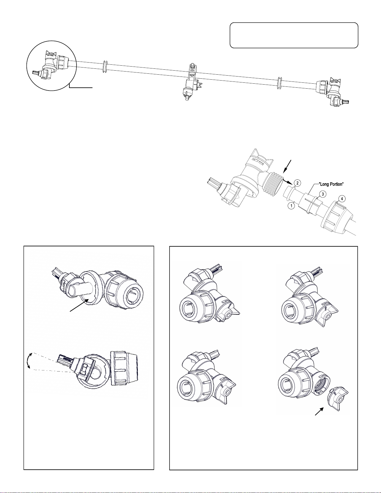
Using the Boom Nozzles
Four things must be considered before spraying with the boom.
How much chemical must be mixed in the tank.
Rate of spray (gallons per acre to be sprayed).
What pressure (p.s.i.) will be used.
Speed traveled (mph) while spraying.
Refer to the chemical label to determine your chemical mixture
See the tip chart to determine the pressure to be used. The chart will
also show the speed used when spraying.
Start the pump and open the valve to the boom nozzles.
Check the spray pattern. Usually you can see the coverage better on
a solid concrete surface, such as a driveway.
The boomless nozzles should be approx. 33” above the objects being
sprayed.
Calibration
Chemical labels may show application rates in gallons per acre, gallons per
1000 square feet or gallons per 100 square feet. You will note that the tip
chart shows 3 of these rating systems. Once you know how much you are
going to spray, then determine (from the tip chart) the spraying pressure
(PSI), and the spraying speed (MPH).
Determining the proper speed of the pulling vehicle can be done by
marking off 100, 200 & 300 feet. The speed chart indicates the number of
seconds it takes to travel the distances. Set the throttle and with a running
start, travel the distances. Adjust the throttle until you travel the distances
in the number of seconds indicated by the speed chart. Once you have
reached the throttle setting needed, mark the throttle location so you can
stop and go again, returning to the same speed.
Add water and proper amount of chemical to the tank and drive to the
starting place for spraying.
Adjusting Pressure
When the bypass valve is closed, pressure is at the highest point.
Opening the valve will decrease pressure.
Maintenance During/After Spraying
Proper care and maintenance will prolong the life of your sprayer.
After use, fill the sprayer tank part way with water. Start the sprayer
and allow the clear water to be pumped through the plumbing system
and out through the spray nozzles. Refill the tank about half full with
plain water and use FIMCO Tank Neutralizer and Cleaner and repeat
cleaning instructions above. Flush the entire sprayer with the
neutralizing/cleaning agent, then flush out one more time with plain
water. Follow the chemical manufacturer’s disposal instructions of all
wash or rinsing water.
For the boom (if applicable) remove the tips and screens from the
nozzle assemblies. Wash these items out thoroughly. Blow the orifice
clean and dry. If the orifice remains clogged, clean it with a fine
bristle (NOT WIRE) brush or with a toothpick. Do not damage the
orifice. Water rinse and dry the tips before storing.
WARNING: Some chemicals will damage the pump valves if
allowed to soak untreated for a length of time! ALWAYS flush
the pump as instructed after each use. DO NOT allow chemicals
to sit in the pump for extended times of idleness. Follow the
chemical manufacturer’s instructions on disposal of all waste
water from the sprayer.
Winter Storage
Drain all water out of your sprayer, paying special attention to the
pump, handgun and valve(s). These items are especially prone to
damage from chemicals and freezing weather.
The sprayer should be winterized before storage by pumping a
solution of RV antifreeze through the entire plumbing system. This
antifreeze solution should remain in the plumbing system during the
winter months. When spring time comes and you are preparing your
sprayer for the spray season, rinse the entire plumbing system out,
clearing the lines of the antifreeze solution.

Page 4
End Nozzle Assembly
5275122
Exploded View/Parts List: 800-BL30NS (5301649)
Center Nozzle Assembly
5275123

Page 5
NOTES:

Page 6
LIMITED WARRANTY FOR NEW FIMCO, IND. EQUIPMENT
WHO MAY USE THIS LIMITED WARRANTY. This limited warranty (the “Limited Warranty”) is provided by Fimco, Ind. to the original purchaser
(“you”) of the Equipment (as dened below) from Fimco, Ind. or one of Fimco, Ind.’s authorized dealers. This Limited Warranty does not apply to
any subsequent owner or other transferee of the Equipment. THIS LIMITED WARRANTY GIVES YOU SPECIFIC LEGAL RIGHTS, AND YOU MAY ALSO
HAVE OTHER RIGHTS WHICH VARY FROM STATE TO STATE.
WHAT THIS LIMITED WARRANTY COVERS AND FOR HOW LONG. Fimco, Ind. warrants that any new Equipment will be free from defects in
material and workmanship for a period of one (1) year (homeowner), 90 days (commercial user), aer delivery of the Equipment to you (the
“Warranty Period”). The Warranty Period is not extended if Fimco, Ind. repairs or replaces the Equipment.
WHAT IS NOT COVERED BY THIS LIMITED WARRANTY. This Limited Warranty does not apply to: (1) used Equipment; (2) any Equipment that has
been altered, changed, repaired or treated since its delivery to you, other than by Fimco, Ind. or its authorized dealers; (3) damage or deprecia-
on due to normal wear and tear; (4) defects or damage due to failure to follow Fimco, Ind.’s operator’s manual, specicaons or other wrien
instrucons, or improper storage, operaon, maintenance, applicaon or installaon of parts; (5) defects or damage due to misuse, accident or
neglect, “acts of God” or other events beyond Fimco, Ind.’s reasonable control; (6) accessories, aachments, tools or parts that were not manu-
factured by Fimco, Ind., whether or not sold or operated with the Equipment; or (7) rubber parts, such as res, hoses and grommets.
HOW TO OBTAIN WARRANTY SERVICE. To obtain warranty service under this Limited Warranty, you must (1) provide wrien noce to Fimco,
Ind. of the defect during the Warranty Period and within thirty (30) days aer the defect becomes apparent or the repair becomes necessary, at
the following address: Fimco, Ind., 1000 Fimco Lane, North Sioux City, SD 57049; and (2) make the Equipment available to Fimco, Ind. or an
authorized dealer within a reasonable period of me. For more informaon about this Limited Warranty, please call: 800-831-0027.
WHAT REMEDIES ARE AVAILABLE UNDER THIS LIMITED WARRANTY. If the condions set forth above are fullled and the Equipment or any part
thereof is found to be defecve, Fimco, Ind. shall, at its own cost, and at its opon, either repair or replace the defecve Equipment or part.
Fimco, Ind. will pay for shipping and handling fees to return the repaired or replacement Equipment or part to you.
LIMITATION OF IMPLIED WARRANTIES AND OTHER REMEDIES. THE REMEDIES DESCRIBED ABOVE ARE YOUR SOLE AND EXCLUSIVE REMEDIES,
AND FIMCO, IND.’S SOLE LIABILITY, FOR ANY BREACH OF THIS LIMITED WARRANTY. TO THE EXTENT APPLICABLE, ANY IMPLIED WARRANTIES,
INCLUDING, WITHOUT LIMITATION, THE IMPLIED WARRANTIES OF MERCHANTABILITY AND FITNESS FOR A PARTICULAR PURPOSE, SHALL BE LIM-
ITED IN DURATION TO THE WARRANTY PERIOD, AND THE REMEDIES AVAILABLE FOR BREACH THEREOF SHALL BE LIMITED TO THE REMEDIES
AVAILABLE UNDER THIS EXPRESS LIMITED WARRANTY. SOME STATES DO NOT ALLOW LIMITATIONS ON HOW LONG AN IMPLIED WARRANTY
LASTS, SO THE ABOVE LIMITATION MAY NOT APPLY TO YOU. IN NO EVENT SHALL FIMCO, IND.’S LIABILITY UNDER THIS LIMITED WARRANTY EX-
CEED THE ACTUAL AMOUNT PAID BY YOU FOR THE DEFECTIVE EQUIPMENT, NOR SHALL FIMCO, IND. BE LIABLE, UNDER ANY CIRCUMSTANCES,
FOR ANY CONSEQUENTIAL, INCIDENTAL, SPECIAL OR PUNITIVE DAMAGES OR LOSSES, WHETHER DIRECT OR INDIRECT. SOME STATES DO NOT
ALLOW THE EXCLUSION OR LIMITATION OF INCIDENTAL OR CONSEQUENTIAL DAMAGES, SO THE ABOVE LIMITATION OR EXCLUSION MAY NOT
APPLY TO YOU.
Warranty
This manual suits for next models
1
Table of contents
Other SMA Paint Sprayer manuals

SMA
SMA 800-SS8P User manual

SMA
SMA Fimco Pro Series User manual

SMA
SMA 800-UTL60ST User manual

SMA
SMA 800-SS40DX User manual

SMA
SMA 800-TRL40ST User manual

SMA
SMA 800-UTL40ST User manual

SMA
SMA 800-TRL30NS User manual

SMA
SMA 800-ATV25DXBL User manual

SMA
SMA UTV-65-7 User manual

SMA
SMA 800-UTL40BL User manual