Smart Bridge 8811S-GW&9202N-RF User manual

【Quick Installation Guide─RF Gateway and Fall Down Detector】
1 QIG GW-SD 11-2021 / v1.2
➢Preparation
Equipment Required: SmartPhone or Laptop, WiFi Router
Application: Web Browser (Microsoft Edge/ Google Chrome/ Safari...)
9abcx-rf is only a sensor, so it must be combined with gateway 8811 to work
➢Product Photo
Gateway (8811S-GW) Fall Down Detector
➢Gateway Installation
1.1. Install Gateway:Power on the Gateway, the Indicator Light turns Red.
1.2. Indicator Light flashes rend and greed for next installation (AP-Mode)
1.3. Turn on WiFi Setting on SmartPhone/Laptop and connect to Gateway SSID. The format is
like ”SBI-GW-XXXXXXXXXXXXX”, and password ”12345678”.
1.4. Turn on web browser and enter“http://10.42.0.1:8000”(AP-mode connected address)
➢Setting
1.1 RF pairing Process the pairing process for Gateway and Sensor
Press “RF pairing” on web browser and take a fine needle to press the pairing button at
the bottom left of the Detector around 2-5 seconds. The Indicator light flashes green
then take out the fine needle. The pairing process is done after the indicator light turns
solid green for seconds. The sensor number starts from {0}, followed by {1,2…7}. (Up to
8 ). Check it by “Find Sensor” ->” Online Sensor” after 30 seconds after pairing. (Section
1.6)
1.2 Remove all RF devices Remove all the pairing between Gateway and Sensors
Press ”Remove all RF” on web browser and all the pairing between Gateway and Sensors
are invalid.
1.3 WiFi Setting Connect Gateway to WiFi router and connect it by http:// <gateway
IP> :8000. (Client mode). Select the WiFi SSID and enter password of your router. It takes
3-5 minutes for WiFi setting. The Indicator Light turns to Blue after the WiFi setting is
completed. (Blue for Internet accessible; Red means Internet non-accessible)
1.4 API server address setting Modify the server address
You can configure the server address for data upload by this option.
(http://server IP). To upload the Gateway heartbeat and event record.
Please find the API document provided by SBI for more detail.
1.5 Read slip trigger log Read the fall down event record
You can check the time record table of fall down event from this option. It will keep the
last 50 data. The data will be completely removed and re-recorded after Gateway power
Indicator Light
Pairing
Button
Indicator
Light
Sensor
【Quick Installation Guide─RF Gateway and Fall Down Detector】
2 QIG GW-SD 11-2021 / v1.2
on again.
1.6 Find Sensor Check all the pairing list and status of Gateway and Sensors
Online sensor: The sensor list for pairing to Gateway and online. Ex: Sensor {0}
Offline sensor: The sensor list for pairing to Gateway and offline. NULL means none.
Not paired: The sensor list that are not paired with Gateway. (Sensor 1 to 7)
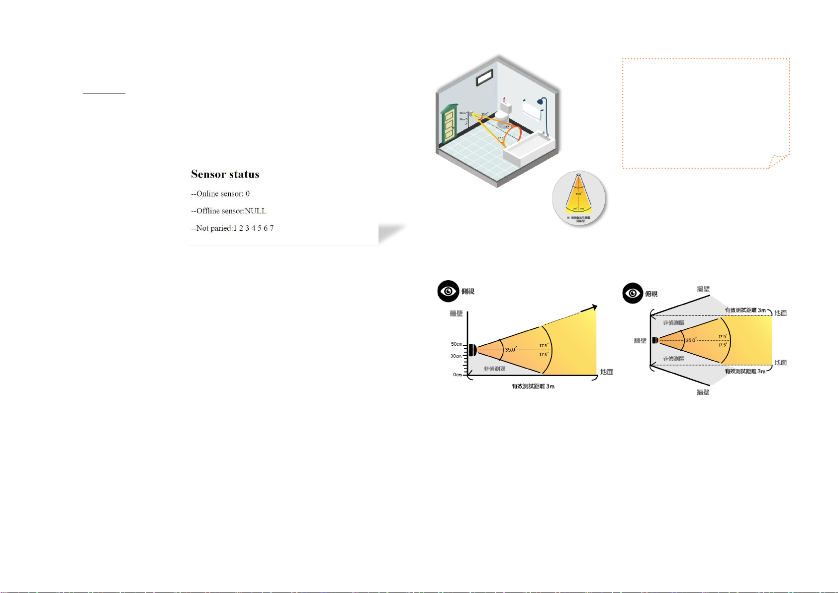
➢Fall Down Detector Installing and Testing
1. Please place the sensor to the place where you prefer. Such as bathroom, bedroom or bedside
etc. (*Note:Illustrate it by bathroom)
2. Find a suitable wall for installing the detector under the detected area. (refer to below photo)
3. Install location: Find the position where the wall is 40-50 CM away from the ground. (mark)
4. Attach the top of sensor to the mark and install completed.
★Reminder:Be sure to process pairing before installation.
★The distance should not exceed 1 meter while pairing.
5. The fall down detector will perform self-environment calibration after re-power. The indicator
light will start to flash. It keeps on for test starting. And the indicator light turn off after testing
done. It takes around 2 minutes. Please keep the detected area empty under calibration.
6. Make sure the indicator light turns off and ready for testing. A person walk into the detected
area and falls down (LED flashes red light), lying down and last for about 30 seconds without
sharp movement). The indicator light will stay on Red and the fall down event is triggered by
sensor.
▲Schematic diagram of sensor light emission (side view/top view)
備註:
⚫The standard USB cable for fall down detector is 80 cm length. If that is not suitable for
usage and it is recommended to purchase a dual-connected USB extension cable on the
market.
⚫Here is download site for our user manual:
Chinese website: http://www.smartbridge-info.com
English website: http://www.smartbridge-tech.com
★整體示意圖(圖九)
*Reminder~
The sensor needs to be installed at a
distance of 40~50 cm from the
ground to produce a 35 degrees
detection range. (Pyramid)。

【Quick Installation Guide─RF Gateway and Fall Down Detector】
3 QIG GW-SD 11-2021 / v1.2
[ Warning ]
Herty, Smart Bridge Information Inc. declares that this 8811S-GW&9202N-RF is
in compliance with the essential requirements and other relevant provisions of
Of Directive 2014/53/EU.
In accordance with Article 10(2) and Article 10(10), this product allowed to be
used in all EU member states.
Use the 8811S-GW&9202N-RF in the environment with the temperature between
15 degree and 33 degree in Celsius.
Adapter shall be installed near the equipment and shall be easily accessible.
The plug considered as disconnect device of adaptor
Adaptor Model: PG062-0501000EB
Input AC: 100-240V 50/60Hz 0.3A Output: DC 5.0V, 1A
Manufacture: Pgtec Technology Co., Ltd.
Address: 3rd Floor, Building A, Yinhai Industrial Park, Nanming Road, Guangming District,
Shenzhen, China
E-mail: tonyliu@hkpgtec.com
FCC Statement
Changes or modifications not expressly approved by the party responsible for compliance
could void the user's authority to operate the equipment.
This equipment has been tested and found to comply with the limits for a Class B digital
device, pursuant to Part 15 of the FCC Rules. These limits are designed to provide
reasonable protection against harmful interference in a residential installation. This
equipment generates uses and can radiate radio frequency energy and, if not installed and
used in accordance with the instructions, may cause harmful interference to radio
communications. However, there is no guarantee that interference will not occur in a
particular installation. If this equipment does cause harmful interference to radio or
television reception, which can be determined by turning the equipment off and on, the
user is encouraged to try to correct the interference by one or more of the following
measures:
-- Reorient or relocate the receiving antenna.
-- Increase the separation between the equipment and receiver.
-- Connect the equipment into an outlet on a circuit different from that to which the
receiver is connected.
-- Consult the dealer or an experienced radio/TV technician for help
This device complies with part 15 of the FCC rules. Operation is subject to the following two
conditions (1)this device may not cause harmful interference, and (2) this device must
accept any interference received, including interference that may cause undesired
operation.
This equipment complies with FCC radiation exposure limits set forth for an uncontrolled
environment. This equipment should be installed and operated with minimum distance
20cm between the radiator & your body.
Other Smart Bridge Security Sensor manuals


