manuals.online logo
Brands
  1. Home
  2. •
  3. Brands
  4. •
  5. System Sensor
  6. •
  7. Security Sensor
  8. •
  9. System Sensor WFD20 User manual

System Sensor WFD20 User manual

SysTEMM
SENSOR
INSTALLATIoN
AND
MAINTENANCE
INSTRUCTIONS
rech
Intral
Deeiogmrnt
Zan
WFD
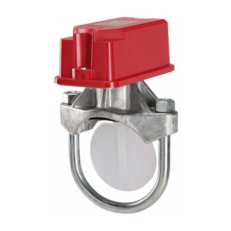
Vane-type
Waterflow
Detectors
Prinee
f Sh
aam.
71
0075,
Chi
Teiephone
(29
347800
Fas
(037)
382959
SPECIFICATnONS
Contact Ratings:
higgering Threshold Bandwidth
(Flow
Rate):
Static
Pressure
Rating
Dimensions, Installed:
l0
A
@
125/250
VAC
N
25
A@
24
VDC ---
4 to
10
gpin
See
models listed below
3.5
in
Hx
30
in
W x6.7 in D
Operating
Temperature
Range:
Compatible
Pipe:
Shipping
Weight:
Enclosure Rating:
U.
S.
Patent
Numbers
32°F
to
120°F (0°C
to
49°C)
Steel
water
pipe,
schedule
10
through
40
4 to 7 Ib
(according
to
size)
NEMA Type 4,
as
tested
by
Underwriters
Laboratories,
Inc. (1PS6)
5,213,
3,205
IMPORTANT
INSTALLATmON
GUIDELUNES
Please Read Carefully
And
Save
Before
instaling any waterflow alarm device,
be
thoroughly
farmiliar
with:
This
instructionmanual
contains
important
information
about
the
installation
NFPA
72:
National
Fire
Alarm
Code
and
operation
of
waterlow
detectors.
Purchasers
who install waterflow
detec
tors
for
use by others must leave this manual or a copy of
it
with the user.
NFPA
13:
Installation
of
Sprinkler Systems, Sect.
3.17
NFPA
25:
Inspection.
Testing
and
Maintenance
of
Sprinkler
Systesms,
Sect
5332
Read all instructions carefully before beginning. Follow only those instnuc-
tions that apply to the model you are installing.
Other
appiicable
NFPA
standards,
local
codes,
and
the
requiremenits
of
the
authority having jurisdiction
ACAUTION
NOTE:
Installation
methods
other
than
those listed in this instaliation
manual
Use vane-type
waterlow
detectors in wel-pipe systems only.
Do
NOT
use
Imay
preven!
tihe
device
irom
reporiing
the
Llow
oí
water
in
the
event
the
asso-
them in dry pipe, deluge.
or
preaction systems. The
sudden
inrush
of
water in ciated sprinkier system
is
activated by a ire.
XTan
Sysem Sensor is not responsible
such systems may break the vane or damage the mechanism. for
devices
that
have
been
improperiy
installed, tested,
or
maintained
Do
not use in potentially explosive atmospheres.
Do
not
allow
unused wires
lo
remain
exposed.
1.
Mount the detector where there
is
adequate clearance tor installation and
removaB
and
a clear view
of
it
for inspections. See Figure I for
maunting
dimensions.
2.Locate
the
detector 6
to
7
feet
above
the
floor
to
protect
from
acca
dental damage.
PRINCIPLES OF OPERATION
Vane-type waterflow detectors imount to water-filled pipes in sprinkler systems.
Waterflow in the pipe deflects a vane, which produces a switched
outpul
3.
On
horizontal runs, position the detector
on
the top or side
of
the
pipe.
usually
after
a specilied delay.
All
waterflow detectors have a
pneumatically
controlled mechanical delay mechanism. Delays do
NOT
accuinulate; they
re
set
if the
flow
of water stops before the entire delay has elapsed.
All
switches
actuate
when
the water flow rate is
10
gallons per minute or greater, but will
not actuate
if
the
low
rate is less than 4 gallons per minute. This System
Sen-
sor
installation manual
covers
the
following
watertlow detectors
for
sprinkler
ire
alarm
applications.
Do
not
mount
it
upside
down
because
condensation
may
collect in the
housing
and
impair
thse
operaüon
of
he
detector. For vertical flow appli-
Ccations,
mount
the
detector on
pipe
through which water fiows upward.
Otherwise, the unit
mnay
not operaie properiy.
4.
Mount
the
detector
at
least
6
inches
fron
a
f+itüng
that
changes
the
direc-
tion
of
water tlow
and
no less than 24 inches irom a valve
or
drain.
5.
Be
sure
the
direction-of-low
aToW
matches
the
directOn
of
llow in the pipe.
Pipe
Size
Pipe Max.
Pressure
MOUNTING
INSTRUCTiONS
Model
(inches)
Schedule
Rating
(psig)
1.
Drain
the
pipe.
WFD20
10
thru
40
450
Cut a hole
at
the desired location. Center the hole
in
tbe pipe, às
shown
in
Figure
2,
and
be
sure the hole
is
perpendicular
to
the
center
of
the
pipe. Before drilling. use a punch or scribe
to
mark the
dill
site
to
pre
vent
the
bit
trom
slipping.
If
the
hole
is
off
center,
the
vane
will
bind
gainst
the inside wall of the pipe.
Use
a
dril
or hole saw
to
cut a hole of
the
proper
diameter.
See Table I tor hole size.
WFD25 2.5 10 thru
40
450
WFD30-2
10
thru
40
450
WFD35
3.5
10 thru
400
450
WFD40
10
thru
40
450
WFD50
10 thru
40
450
ACAUTION
When
drilling
the
hole
with
a
hole
saw,
make
certain
that
the
center
ot
the
cut
does nol
remain
in
the
pipe.
WFD60 10 thru 40
450
WFD80
10
thru
40
450
Kemove
burrs and sharp edges
from
the hole. Clean and remove
all
scale
and
toreign
matter
trom
the
inside
ot
the
pipe
lor
one
diameter
on
each
Side
of
the
hole to
ensure
free
movement
of the
vane.
Clean
the
outside
of
the
pipe
to
remove
dirt,
metal
chips,
and
cutting
lubricant.
Maximum Ptressure
Rating
400
psig
as
approved
by
Factory
Mutual
Research.
ACAUTION
Do
NOT
use any
of
the
WFD
models on copper pipe. The clamping 1orces . Seat the gasket against the saddle and mount the delector directly
to
the
the
mounting
bolts may
collapse
the
pipe
sufficiently
to
prevent
the
detector
from
functioning properly.
pipe.
Carefully
roll
the
vane
opposite
the
direction
of
tlow
and
insert
through the hole. Seat the saddle firmly against the pipe
so
that the local-
ng
boss
goes
into
the
hole.
Do
NOT
install
steel
or
iron
pipe
sections
in
copper
piping
for
mounting
waterflow detector. Incompatibility
between
the
dissimilar metals causes b
ustnal
Development
Zone
Province
o1
Shaanxi,
710075,
China
Telephone: (029) 8S387800 Fax: (029) 88332959
metallic corrosion.
D770-01-00C
I56-0459-017C
he
-boli,
tightening
the
nuts
alernately
to
ensure
a
unilform
seal
PRE-OPERATION
TESTING
(see
Table
1
for
torque
values)
6.
Remove
the metal
cover
with
the
tamper-proof
wrench
provlded.
ove
Ihe
actuator lever
back
and
forth
to
check
for
binding.
I the
vane
binds, re*
move
the
detector and correct
the
cause
before
proceeding
.
Fill
the sprinkler system and check
lor
leaks around the waterflow detec-
tor.
If
it
leaks,
first
check
for
the proper torque on the
U-bolt
nuts.
If
the
leak
persists,
drain
the
system
and
remove
the
detector
(reler
to
Mainte
nance). Check
for
dirt or foreign objects under the gasket. and make sure
that
the
pipe
surface
is
not
dented.
Reinstall
the detector
and
check
again
for
leaks.
Do
not proceed until
all
leaks have been stopped.
ACAUTION
Be
sure the direction-of-low
arow
points
in
the
right
direction
or
else
water
2.
Connect
an
ohmmeter or
econtinuity
tester
actos
the
COM
and
B-NO
low
will
go
unreported.
See
Figure
3 switch terminals. The
ohnmeter
should indicate an open clrcuít.
3.
Deflect the actuator lever and hold
it
until the pneumatic delay shaft
releases the switch buttons. The ohmmeter or continuity tester should
show a
short
circuit
after
the
delay
has
elapsed.
If
there
is no delay,
check
the setting of
the
delay
adjustment dial.
FIaURE
1.
MOUNTING
DIMENSIONS
_95mm
(3/T)
FiGURE
3.
AsSEMBLY DIAGRAM:
-COVER
TAMPER
PROOF
WRENCH
(P/N
WFDW)
76mm
(3)
PIPE
DIAMETER
PLUS
133mm
(5)
U-BOLT
NUT
TERMINAL
BLOCK
(REPLACEMENT
P/N
A77-01-02)
h,|
PIPE
SADDLE
DELAY
MECHANISM
(REPLACEMENT
(P/N
A3008-00)
ELECTRICAL
CONDUIT
ENTRANCE
PIPE
MOUNTING
PLATE
PIPE
VANE
U-BOLT
NUT
PIPE SADDLE
U-BOLT
PLASTIC
VANE
ROLL
PADDLE
OPPOSITE
OF
FLOW
ARROW
WHILE
INSERTING
OVERALL
IDTH
= PIPE
DIAMETER+76mm
(3)
FIGURE
2.
MOUNTING HOLE LOCATION: SADDLE GASKET
WRONG
PIPE
RIGHT
WATERFLOw
REFER
To
TABLE
1
U-BOLT
WIRING
REMOVE
BURRS
FROM
EDGE
OF
HOLE.
CLEAN
OUT
SCALE
AND
FOREIGN
MATTER
FROM
INSIDE
WALL
OF
PIPE.
1.
All
models have two
SPDT
switches. Switch contacts
COM
and
B-NO
are
closed when water
is
lowing and open when
it
is
not.
Connect
the
switches,
as
shown
in
Figure
4,
depending
on
the
application.
When
connected
to
a listed sprinkler/fire alarm control panel,
the
initat-
ing
circuit
must
be
nonsilenceable.
TABLE
1:
WFD
MODEL
HOLE
SIZE
(IN)
TORQUE
A
ground
screw
is
provided
with all waterflow detectors. When
ground
ing
ls
required, clamp wire with serew
in
hole located between condult
entrance
holes. See
Figure
SA,
page
4.
f a second conduit
enuy
is
required, remove the knockout plug using à
1lat
blade
screwdriver
as
shown
on
Figure
5B,
page
4.
Strike
sharply
ith
a
hamner
to
pierce the
wall
of
the knockout plug.
Move
to
an adjacent
wall
section and repeat until the plug
falls
out.
Make
sure that the watertlow
detector
is
supported
alequately
during
this
operatlon
to
avoid
injury
20,
25
14
30-35
It-b.
30-2,
35, 40, 50, 60,
80|
2 55-60 fl-lb.
D770-01-0OC
156-0459-017C
tem
Sensor
is
not
responsible
tor
devices
that
have
been
Improperly
instaled.
tested,
or
maintained.
AAWARNING
High
Voltage.
Electrocution
Hazard.
Do
not
handle
live
AC
wiring
or
work
on
a
device
io
which
AC
power
is
applied.
Doing
s0
may
result
in
injury
or
death.
To
remove a
detector
When
utilizing
switches
at
voliages greater
than
74VDC
---
or
49VAC
means
to
provide
all-pole
disconnection
must
be
incorporaled
in
the
fixed
wiring,
such
as
a
circuit
breaker.
1.
Drain
the
pipe.
2.
Turn
off
electrical
power
to
the
detector
and
disconnect
the
wiring.
3.
Loosen
the
nuts
and remove
the
U-bolts.
Genly
lift
the
saddle
íar
enough
to
get
your
fingers
under
it.
Then,
roll
the
vane
so
it
will
tit
through
the
bole
while
continuing
to
lift
the
water
flow
detector
saddle.
FIaURE
4.
WFD
WIRIN0
NOTE:
COMMON
AND
B-NO
CONNECTiONS
WILL
CLOSE
WHEN
VANE
IS
DEFLECTED,
LE
WHENWATER
IS
FLOWING.
DUAL
SWITC
NG
TO
BE
COMBINED
ON
A
SINGLE
DETECTOR
SSM24-X
SSV120-X
5.
Lift
the
detector
clear
of
the
pipe.
LISTED
COMPATIBLE
ACAUTION
f a
vane
breaks
in a
pipe,
find and remove
it.
If
it
is
not
removed,
the
vane
may
resuict
the
low
ol
water
to
all
or
part
of
the
sprinkler
system.
CONTROL
PANEL
POWER
24VDC
OR
120VDC
suGGESTED
EOL
HESISTON
CONTACT
RATINGS
125/250
VAC
10
AMPS
L24
VoG|
26
AMPS
INITIATING
LOOP
FIGURE
SA.
GROUND
SCREW
LOCATION:
sCHEMATIC
OF
INDIVIDUAL
IN
-GROUNND
SCREW
(GREEN)
SWTCH
C
"NO
WATERFLOW
CONDITION
BREAK
WIRE
AS
SHOWN
ON
OF
SEON
DO
NOT
ALLOW
STRIPPED
WIRE
LEADS
TO
EXTEND
BEYOND
SWITCH
HOUSING.
DO
NOT
LOOP
WIAES.
T
-MOUNTING
PLATE
J
FIGURE
SB.
KNOCKOUT
PLUG
REMOVAL:
MECHANICAL
DELAY
ADJUSTMENT
The pneumatic delay
is
preset at the factory to 30
scconds.
To
adjust
the
set-
ting, turn the adjustment dial clockwise
to
increase the delay,
counterclock
wise to decrease
it.
The
delay
is
adjustable
from
0
to
90 seconds. See
Figure
6,
page
4.
NOTE:
Set
the
delay
to
the
minímum
required
to prevent
false
alarms
from
flow
surges.
Periodically
test
time
delay
as
required
by
Authority
Having
Jurisdiction
or
code authority.
OPERATIONAL
TESTING
Always
notifly
a
central
station
monitoring
waterflow
alarms
before
repairing.
maintaining.
or
testing waterflow alarm devices.
1.
Replace
the
cover
and
tighten
the
tamper
proof
screws
with
the
lamper
proof
wrench.
Store
the
wrench
in
a
secure
place.
FIGURE
6.
DELAY
ADJUSTMENT DIAL:
2.
Open
the
inspector's
test
valve
and
time
how
long
it
takes
for
the
detec-
tor
to
indicate
a
low
condition.
The
detector
should
remain
activated
un-
til
the
inspector's
test
valve
is
closed.
Air
pockets
in
the
sprinkler
system
may
increase
the
apparent
delay.
DELAY
USTMENT
DIAL
ON
DIAL
IS
APPRO
oPROXIMATE
SECONDS
ER
DELAY
IN
UM
DIME
DEL
MAINTENANCE
To
prevent
accidental
water
damage,
conirol
valves
should
be
shut
tight
and
the
system
completely
drained
before
waterílow
detectors
are
removed
or
re-
placed.
Inspect
detectors
in
accordance
with
applicable
NEPA
codes
and
standards
and/or
the
authority
having
jurisdiction
for
leaks
and
replace
if
a
leak
occurs.
Test
detectors
al
least
quarterly,
as
described
under
Operational
Testing.
to
ensure
proper
operation.
Test
more
often
if
required
by
the
authority
having
jurisdiction.
.
Under
nonal
conditions,
Xian
System
Sensor
waterilow
detectors
should
provide
years
of
truubie-íree
service.
However,
if
the
delay
mechanis1n
or
switch
en-
closure
needs
to
be
replaced,
follow
these
directions.
To
replace
the
delay
mechanism
or
switch
enclosure,
use
a
3/16
socket
head
screwdriver
to
re-
move
the
three
screws
that
hold
it
in
place.
Either
mechanism
can
be
easily
replaced
without
removing
the
detector
from
the
pipe
or
draining
the
pipe.
10
replace
the
delay
mechanism1,
request
Part
No.
A3008-00.
For
switch
enclo
sure,
request
Part
No.
A77-01-02.
Do
not
repair
or
replace
any
other
waterilow
detector
components.
I[
any
other
part
of
the
detector
does
not
perform
prop
erly,
replace
the
entire
detector.
Installation
methods
other
than
those
listed
in
this
installation
manual
may
prevent
the
device
from
reporting
the
flow
ol
water
in
the
event
the
associated
sprinkler
system
is
activated
by
a
fire.
Sys*
45
JUL
NOTE:
RETARD
TIME
MAY
EXCEED
90
SECONDSADJUS
SE
NDS
ANOE
APPROXMATE
TIME
DELAY
IN
NUMBER
ON
OIALISA
VOE
50o.
SECONDS
WITH
AN
ACCURACY
OF
-
50%.
D770-01-0OC
156-0459-017C

This manual suits for next models

8

Other System Sensor Security Sensor manuals

System Sensor CO1224T User manual

System Sensor

System Sensor CO1224T User manual

System Sensor B110LP User manual

System Sensor

System Sensor B110LP User manual

System Sensor B401BR750 User manual

System Sensor

System Sensor B401BR750 User manual

System Sensor 1112/24D User manual

System Sensor

System Sensor 1112/24D User manual

System Sensor B501 User manual

System Sensor

System Sensor B501 User manual

System Sensor FAAST 9400X User manual

System Sensor

System Sensor FAAST 9400X User manual

System Sensor WFDTNRN User manual

System Sensor

System Sensor WFDTNRN User manual

System Sensor WFD Series User manual

System Sensor

System Sensor WFD Series User manual

System Sensor WFD Series User manual

System Sensor

System Sensor WFD Series User manual

System Sensor Smoke Detector Spacing on Level Ceilings with Beams and... Quick reference guide

System Sensor

System Sensor Smoke Detector Spacing on Level Ceilings with Beams and... Quick reference guide

System Sensor WFD20EXP User manual

System Sensor

System Sensor WFD20EXP User manual

System Sensor B401R User manual

System Sensor

System Sensor B401R User manual

System Sensor RTS151KEYA User manual

System Sensor

System Sensor RTS151KEYA User manual

System Sensor B501BI-IV User manual

System Sensor

System Sensor B501BI-IV User manual

System Sensor B110RLP User manual

System Sensor

System Sensor B110RLP User manual

System Sensor Accuflow LFD20 User manual

System Sensor

System Sensor Accuflow LFD20 User manual

System Sensor DH400 User manual

System Sensor

System Sensor DH400 User manual

System Sensor B224RB User manual

System Sensor

System Sensor B224RB User manual

System Sensor OSI-RIE Series User manual

System Sensor

System Sensor OSI-RIE Series User manual

System Sensor WFDT User manual

System Sensor

System Sensor WFDT User manual

System Sensor B501AP User manual

System Sensor

System Sensor B501AP User manual

System Sensor B224RB User manual

System Sensor

System Sensor B224RB User manual

System Sensor DUCTSD240 User manual

System Sensor

System Sensor DUCTSD240 User manual

System Sensor B110LP User manual

System Sensor

System Sensor B110LP User manual

Popular Security Sensor manuals by other brands

Buckingham 60007 instructions

Buckingham

Buckingham 60007 instructions

PCB Piezotronics 1203-15A Installation and operating manual

PCB Piezotronics

PCB Piezotronics 1203-15A Installation and operating manual

Vega VEGAPULS C 21 operating instructions

Vega

Vega VEGAPULS C 21 operating instructions

Zircon StudSensor L70 OneStep user manual

Zircon

Zircon StudSensor L70 OneStep user manual

BRITBE G3 PRO instruction manual

BRITBE

BRITBE G3 PRO instruction manual

Transmitter Solutions iGAZER50LR instruction manual

Transmitter Solutions

Transmitter Solutions iGAZER50LR instruction manual

Dynalog C-SCAN 2000 Series Operator's manual

Dynalog

Dynalog C-SCAN 2000 Series Operator's manual

Dräger X-plore 5500 Instructions for use

Dräger

Dräger X-plore 5500 Instructions for use

Bosch DS1103i installation instructions

Bosch

Bosch DS1103i installation instructions

GE Motion Sensor user manual

GE

GE Motion Sensor user manual

X4-Life 701445 user manual

X4-Life

X4-Life 701445 user manual

Aqara TH-S02D user manual

Aqara

Aqara TH-S02D user manual

Weco CDZ Series user manual

Weco

Weco CDZ Series user manual

Olympus EPOCH 6LT user manual

Olympus

Olympus EPOCH 6LT user manual

Heiman HM-807DWP manual

Heiman

Heiman HM-807DWP manual

suprema BioEntry Series installation guide

suprema

suprema BioEntry Series installation guide

iProTech Protect 1207i user manual

iProTech

iProTech Protect 1207i user manual

EVE 20EBG8701 Get started

EVE

EVE 20EBG8701 Get started

manuals.online logo
manuals.online logoBrands
  • About & Mission
  • Contact us
  • Privacy Policy
  • Terms and Conditions

Copyright 2025 Manuals.Online. All Rights Reserved.