1 Box contents
Make sure you receive all items of your shipment:
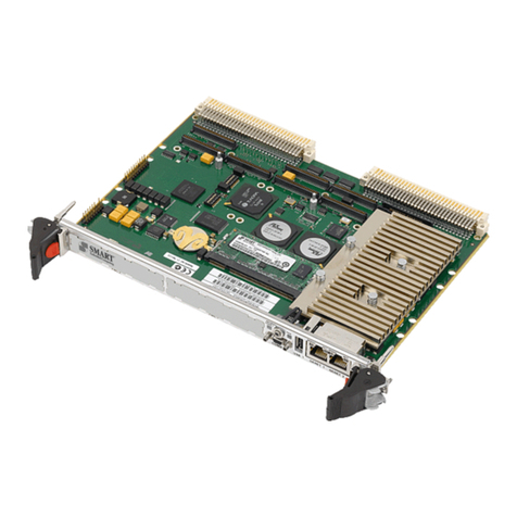
• MVME3100 board
• One printed copy of Quick Start Guide (this document)
• One printed copy of Safety Notes Summary
When installing or servicing the system or accessories,
strictly observe the safety precautions in the Safety Notes
Summary. Ignoring these instructions can void the system
warranty and cause personal injury or property damage.
2 ESD
Electrostatic discharge and incorrect installation or
removal of the card can damage circuit or shorten its life.
Use a properly grounded ESD wrist strap or work in an
ESD-safe environment.
Connect to the ESD connector at the front or the rear of
the system.
3 Site preparation
1. Make sure that all environmental and power requirements
defined in the MVME3100 Installation and Use manual are
met.
2. Remove all items from the box.
4 Configure Hardware
To produce the desired configuration and ensure proper operation of
the MVME3100, you may need to carry out certain hardware
modifications before installing the module. For more information,
refer to the MVME3100 Installation and Use.
5 Install the Board
Note: Before removing the housing cover make sure that the
system is shut down and disconnected from AC power.
1. Attach an ESD strap to your wrist.
2. Attach the other end of the ESD strap to an electrical ground.
The ESD strap must be secured to your wrist and to ground
throughout the procedure.
3. Remove any filler panel that might fill the slot.
4. Install the top and bottom edge of the MVME3100 into the guides
of the chassis.
5. Make sure the levers of the two injector/ejectors are in the
outward position.
6. Slide the MVME3100 into the chassis until you feel resistance.
7. Simultaneously move the injector/ejector levers in an inward
direction.
8. Verify that the MVME3100 is properly seated.
9. Secure the board to the chassis using the two screws located
adjacent to the injector/ejector levers.
10.Connect the appropriate cables to the MVME3100.
11.When the MVME3100 is installed in the chassis you are ready to
connect peripherals.
6 Connect Peripherals
The following table lists the available connectors on MVME3100.
MVME3100 Single
Board Computer
Quick Start Guide
P/N: 6806800M29C September 2019
Connector Function
J4 PMC expansion connector
J11, J12, J13, J14 PCI mezzanine card (PMC) slot 1 connector
J21, J22, J23 PCI mezzanine card (PMC) slot 2 connector
J24 Boundary scan header
J25 COP header
J27 USB connector
J28 Front panel SATA connector
J29 Planar SATA connector
J30 Planar SATA power connector
J41B 10/100/1000Mb/s Ethernet connector
J41A COM port connector
P1, P2 VME backplane connectors
J1A, J1B, J1C, J1D COM port connectors
J2A 10/100/1000Mb/s Ethernet connector
J2B 10/100Mb/s Ethernet connector
J10 PIM power/ground
J14 PIM I/O
P2 VME backplane connector
