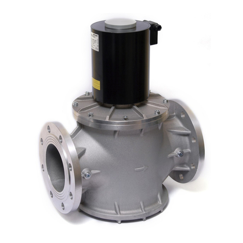
Elektrogas VMM User manual

Printed in Italy - EE163/0704
VMM
Multiple safety solenoid valve
for Gas regulating trains
DN32 … DN50
VMM402AS30
Certified Quality System
www.elektrogas.com

2Printed in Italy - EE163/0704
VMM
Multiple safety solenoid valve
for gas regulating trains
Class A - Group 2
The VMM type valve is a combination of two solenoid
valves in an only compact and versatile valve housing.
This device is suitable for air or gas blocking and
releasing controls (with one or two stages operation),
required in gas power burners, atmospheric gas boiler,
furnaces and others gas consuming appliances.
The VMM type valve is made in accordance with EN161
standard (EC type examination certificate no.
0063AQ1350).
1- Features
Inlet/outlet connection flanges are easy detachable
to simplify the installation.
Provided with bilateral G1/4” pressure gauges in all
pressure chambers.
Optional G1/8” connection for closed position
indicator micro switch.
Fine mesh filter incorporated prevents dirty
contamination of the seal seat.
Maximum operating pressure 200 mbar or 360
mbar.
Suitable for air and non-aggressive gases (EN 437,
1, 2 and 3 families).
Easy adjustable flow rate, fast stroke and slow
opening time.
Qualified for continuous service (100% ED) and
endless ON/OFF cycles.
Coil insulation is class H (180°C).
Terminal box with PG connector.
Provided with a power saving electronic device, to
reduce power consumption and working
temperature.
Valves are 100% tested by computerized testing
machineries and are fully warranted.
For valve identification see the following charts.
WARNING
- This control must be installed in compliance with
the laws in force.
- Read instructions before use.
- Elettromeccanica Delta S.p.a. reserves the right
to update or make technical changes without
prior notice.
Fig. 1
2- Technical specifications
Connections ………………. Gas threaded ISO 7/1
Rp1¼, Rp1½ and Rp2
Flanged PN16 - ISO 7005
with optional kit for
DN40 and DN50
By-pass size ………………. 1/2" and 1"
Voltage rating ………………230 VAC 50/60 Hz
Voltage on request …………110 VAC 50/60 Hz
Voltage tolerance …………. -15% / +10%
Power consumption ………. 90W (working)
by-pass 1/2" 25W
by-pass 1" 45W
Max. opening current ……...2A for 1sec.
Environment temperature …-15°C / +60°C
Max. working pressure …… 200 / 360 mbar
Flow capacity ……………… see charts
Disc sealing ……..………… NBR
Closing time ……………….. < 1 sec.
Protection class …………… IP 54 (EN60529)
Cable gland ………………...PG9
Overall dimensions ……….. see charts

3Printed in Italy - EE163/0704
3- Operation
The VMM type valve is a safety shutting device using
auxiliary power supply.
The first valve (A) is a fast opening solenoid valve that is
safety. When it is de-energized, the spring pushes on
the seal disc, keeping the gas passage closed. Now, the
inlet chamber is under the gas line pressure, and it
forces on the disc too, improving the seal.
When the coil is powered the valve opens rapidly,
against the strength of the spring and gas pressure.
If the power supply is shut off, the valve rapidly closes,
interrupting the gas flow.
Equally, the second valve (B) may be a fast opening or a
slow opening solenoid valve to adjust the gas flow, with
a first adjustable fast stroke and a second adjustable
slow stroke (see the Service Instruction Section).
It is possible connect a third by-pass valve (C), which
performs by driver stage or to obtain a second fast
(slow) stroke or both.
4- Accessories
A fine mesh filter is provided, to prevent dirty
contamination of the seal seat. However, an external
strainer must be installed upstream of the unit.
Each pressure chamber is provided with bilateral G1/4"
gauges, to connect min/max adjustable pressure
switches, leakage tester or other gas equipments.
On request, valves are supplied with a G1/8” connection
on the bottom, to installed a closed position indicator
micro switch. An adapting rod is provided too.
WARNING
The assemblage of any accessories could exclude
the fitting of other devices.
5- Coil features
The continuous service (100% ED) causes inevitable coil
heating, depending of working environment. This
situation is absolutely normal and has not to worry. To
improve the coil cooling, install the unit allowing free air
circulation.
Valve is provided with a power saving electronic device.
It has two stages of operation: full power is supplied to
the coil while the valve is opening; low power is supplied
while the valve is open.
Coil and terminal box are provided with suitable gaskets,
to avoid water and dirty contamination (see the Service
Instruction Section).
Fig. 2
6- General information
Backpressure sealing is compliant with the Class A:
the maximum backpressure admitted, with leakage
within the EN161 requirements, is 150mbar.
Maximum torsional stresses admitted are compliant
with the Group 2 of the EN161 standard.
Recommended testing pressure is 1500 mbar Max.
All components are design to withstand any
mechanical, chemical and thermal condition
occurring during typical service.
Effective impregnation and surface treatments has
been used to improve mechanical sturdiness,
sealing and resistance to corrosion of the
components.
Valves are suitable for use with air and non-
aggressive gases included in the 1, 2 and 3 families
(EN 437).
Materials in contact with gas:
•Aluminium
•Brass
•Stainless steel
•Plated steel
•Anaerobic adhesive
•Nitrile rubber (NBR)
•Polytetrafluoroethylene (PTFE)
1 = Adjustable pressure switch (Min)
2 = Adjustable pressure switch (Max)
3 = Valve leakage tester
4 = Limit switch
5 = Limit switch
6 = Burner pressure gauge
A = First valve
B = Second valve
C = By-pass valve
X = Inlet chamber
Y = Middle chamber
Z = Outlet chamber

4Printed in Italy - EE163/0704
7- Valve identification
VMM 50 2 A S 1 0
Valve type
Connections size
32 = Rp1¼
40 = Rp1½ DN40 (1)
50 = Rp2 DN50 (1)
Max working pressure
2 = 200 mbar
3 = 360 mbar
Supply voltage
A = 230V 50/60Hz
B = 110V 50/60Hz
Second valve type
F = fast
S = slow
By-pass valve on the Right side
(seen from the inlet)
0 = none
1 = ½” (DN15) Fast
2 = ½” (DN15) Slow
3 = 1” (DN25) Fast
4 = 1” (DN25) Slow
By-pass valve on the Left side
(seen from the inlet)
0 = none
1 = ½” (DN15) Fast 3 = 1” (DN25) Fast
2 = ½” (DN15) Slow 4 = 1” (DN25) Slow
(1) Optional kit
Fig. 3
Model Overall dimensions (mm)
A B C D E F G H Weight
(Kg)
VMM….F00 211 280 105 138 170 230 148 13,0
VMM….S00 211 280 105 138 245 305 148 13,7
VMM….S10 211 280 105 138 245 305 200 15,3
VMM….S20 211 280 105 138 245 305 200 15,5
VMM….S30 211 280 105 138 245 305 220 16,3
VMM….S40
Gas threaded
according to
ISO 7/1
211 280 105 138 245 305 220 16,5

5Printed in Italy - EE163/0704
mbar
2
mmH O
NaturalGas
TownGas
Air
m³/h
1"¼
1"½
2"
8- Loss of pressure
Formula of conversion from air
to other gases
Gas type Specific gravity
(Kg/m³) K
Natural Gas 0.80 1.25
Town Gas 0.57 1.48
LPG 2.08 0.77
Air 1.25 1.00
+15°C, 1013 mbar, dry

6Printed in Italy - EE163/0704
9- Valve installation
Verify the line pressure is lower of the maximum working
pressure admitted to the valve.
Check correspondence of flow direction with arrow
printed on valve body.
Check correct alignment of connecting pipes and allow
enough space from the walls to allow free air circulation.
Remove the end caps and make sure no foreign
body is entered into the valve during handling.
Install in an area that is protected from rain and
water splashes or drops.
1. Put sealing agent onto the pipe thread (avoid
excessive quantities of fittings glue which could
enter in the valve and damage the seal seat).
2. Screw the pipes using proper tools only. Do not use
unit as lever because damage to the valve stem
could result. Remove connection flanges to simply
installation.
Avoid overtightening and mount tension free.
Following chart shows the maximum values of bending
moment (Fmax), torque (Tmax) and screws driving torque
(Cmax), according to EN13611.
Connection Fmax
(Nm) t<10 s Tmax
(Nm) Cmax
(Nm)
Rp1¼ 475 160 -
Rp1½ 610 200 50
Rp2 1100 250 50
Fig. 4
Valve may be mounted with coil in horizontal or vertical
position. Coil may be oriented 360 degrees in any
direction.
10- Electrical connections (IEC 730-1)
Check correspondence between valve voltage rating and
line power supply, before making any electrical
connections.
1. Switch off power supply and remove protection
cover.
2. Connect power cables to rectifier circuit terminal
board.
3. Should cables pass through originally closed
opening, use the rubber disc placed underneath the
box plug to close any other opening.
4. Screw back the box cover, taking care to use all
gaskets properly, because this could condition the
valve life duration.
Fig. 5
WARNING
•To prevent product damage and dangerous
situations, read the Installation and Service
Instructions carefully.
•Turn off all power before servicing any part of
the system.
•Perform leak and functional tests after mounting.
A gas leak detection spray may be used also.
•Coil and terminal box must be replaced with
identical spare parts only.
•If the coil is turned, make sure the cap (brake) is
properly tightened and the coil is locked.
•Use all gaskets properly (void warranty).
•All wiring must be in compliance with local and
national codes.
•Make sure all works are performed by qualified
technicians only.
Tmax
Fmax

7Printed in Italy - EE163/0704
11- Flow rate adjustment (Vmax)
Flow rate may be adjusted from 0 cubic meters/h up to
the maximum admitted:
Fast valve type
1. Remove coil fastener cap.
2. Using a 4 mm Allen wrench, remove the locking
dowel.
3. Located under the locking dowel is the flow
regulation screw. Use the Allen wrench to set it.
4. Turn wrench clockwise to decrease or counter-
clockwise to increase flow rate (factory setting is
max. flow rate).
5. When adjustment is completed, screw back the
locking dowel and cap.
Slow valve type
1. Remove plastic cap.
2. Keeping the outer screw fixed, use a screw driver to
turn the internal screw clockwise to decrease or
counter-clockwise to increase flow rate (factory
setting is max. flow rate).
3. When adjustment is completed, screw back the
plastic cap.
12- Fast stroke adjustment (Vstart)
Fast flow section may be adjusted:
1. Remove plastic cap.
2. Using a 7 mm wrench, turn the outer screw
clockwise to decrease or counter-clockwise to
increase the initial fast stroke.
3. When adjustment is completed, screw back the
plastic cap.
NOTE: the flow rate regulation can not be lower than the
fast flow section.
13- Opening time adjustment (T)
To regulate opening time, turn the screw located on the
side of the brake. One fourth of a turn clockwise
increases opening time by 2÷3 s, up to a maximum of
about 25 s (slow run).
Factory setting is about 12÷14 s.
WARNING
•In the slow valve type, perform the fast stroke
adjustment before of the flow rate adjustment.
•Make sure that capacity adjustments are made
while burner is working.
•Check the regulation is not changed during
reassembly.
•Adjustments below 40% of capacity are
unadvisable because they may cause
turbulence.
Fig. 6
1 = Connection flange
2 = G1/4" pressure gauge
3 = Filter
4 = Electrical connections
5 = By-pass flow adjustment
6 = Opening time adjustment (T)
7 = Rapid stroke adjustment (Vstart)
8 = Flow adjustment (Vmax)
A = First valve
B = Second valve
C = By-pass valve
X = Inlet chamber
Y = Middle chamber
Z = Outlet chamber

8Printed in Italy - EE163/0704
13- Maintenance
To maintain a good performance of the system, almost
once a year, an inspection of the valve is recommended.
External inspection
Turn off all power before servicing any part of the
system.
Check the conditions of the terminal board gasket. If
gasket is deteriorated, replace it with a new one.
Check the electrical connections are clean, dry and
correctly tightened.
Check the conditions of pipe connections: cover them
with a soap solution and check for leakages.
Internal inspection
To make an internal inspection of the valve, do the
following:
1. Close ball valve upstream the system.
2. Unscrew the fastening cup (or brake) and remove
the coil.
3. Using an Allen key, remove the screws on the upper
flange, in cross way. The gas in the valve will come
out during this step.
4. Check the hydraulic brake is free of oil leakages
(small leakages are admitted). If it’s necessary,
replace it with a new one.
5. Check the main gasket and, if it’s necessary,
replace it with a new one.
6. Clean the internal side of the stem with a clean cloth
and compressed air.
7. Remove the spring and blow it with compressed air.
Check the spring is corrosion free. Take attention to
the assembly direction of the spring.
8. Check the wear conditions of the sliding rings and, if
it’s necessary, replace them.
9. Clean the plunger assembly with a clean cloth and
compressed air.
10. Check the conditions of the sealing gasket. If gasket
is deteriorated, replace it with a new one.
11. Clean the sealing lip with a clean cloth. Do not use
tools, because a lip damage could result.
12. Reassemble the valve following the inverse
sequence.
To assemble the sliding rings, wind them onto a lower
diameter (ex. Screw driver), then insert them from the
top.
When reassembling, take attention to the correct
position of the sliding rings and spring.
To clean the filter disconnect the valve body from
connection flanges.
Fig. 7
When the reassembly is finished, verify the correct
sealing between the upper flange and the valve body:
1. Open ball valve to restore pressure into the valve.
2. Apply a soap solution between the upper flange and
the valve body and check for leakages.
3. Remove the soap solution with a clean cloth, before
to reassemble the coils.
WARNING
•When reassemble, use all gaskets properly.
•Perform functional test after mounting.
•All works must be executed by qualified
technicians only and in compliance with local
and national codes.
Cap
O-ring
Stem
Scre
w
Upper flange
Spring
Sliding ring
Plunge
r
Disc + gasket
Coil assembly
Brake
O-ring
This manual suits for next models
1
Table of contents
Other Elektrogas Control Unit manuals
Elektrogas
Elektrogas VMM User manual
Elektrogas
Elektrogas VML Series User manual
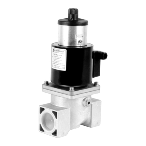
Elektrogas
Elektrogas VML2 User manual
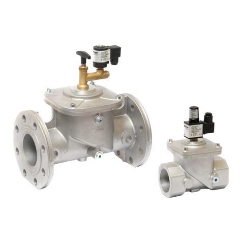
Elektrogas
Elektrogas EVRM-NA User manual
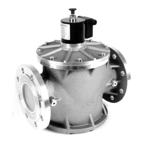
Elektrogas
Elektrogas EVRM-NC User manual
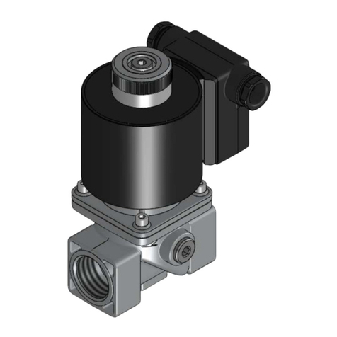
Elektrogas
Elektrogas VMRNA User manual
Elektrogas
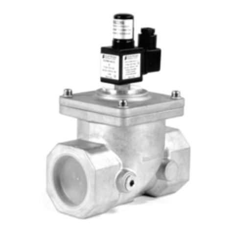
Elektrogas EVRM-NA Series User manual
Elektrogas
Elektrogas VML0 User manual
Elektrogas
Elektrogas VMR01OTN User manual
Elektrogas
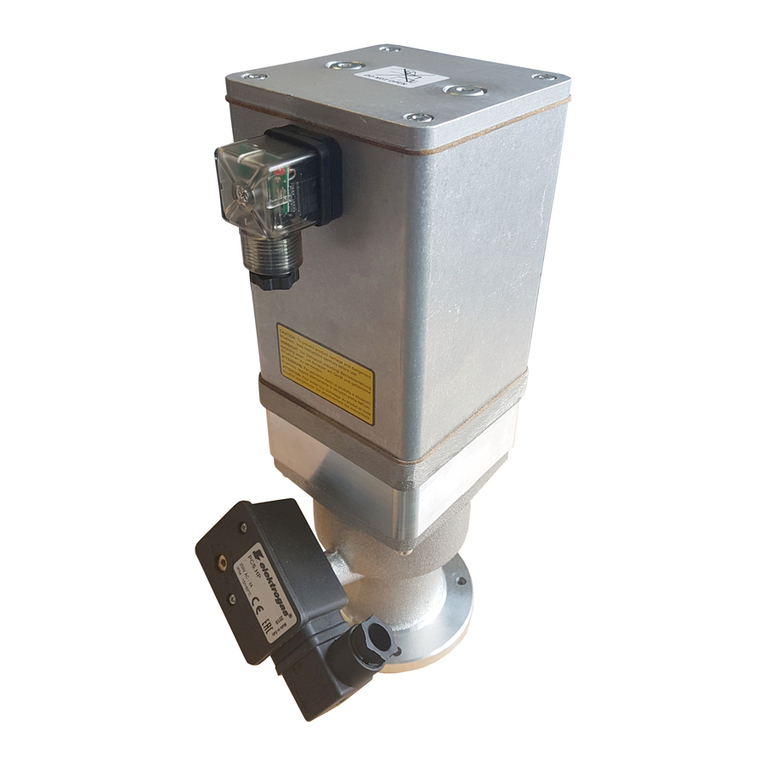
Elektrogas VMH DN Series User manual


