DAV TECH DAS 50N Product manual
360° SPRAY VALVE FOR INTERNAL DAS 50N
DAV TECH SRL
Via Ravizza, 30 - 36075 Montecchio Maggiore (VI) - ITALY
Tel. 0039 0444 574510 - Fax 0039 0444 574324
Installation and
maintenance guide

Index
1 INTRODUCTION pag. 3
1.1 The manual
1.2 Warranty
1.3 Goods receiving
2 TECHNICAL DESCRIPTION pag. 3
2.1 Valve operation
2.2 Technical specifications
2.3 Connection diagram
3 INSTALLATION pag. 4
3.1 Mounting in the machine
3.2 Drive the valve
3.3 Fluid connection
3.4 Setting of the dispensed shot
3.5 Amount of the shot
4 MAINTENANCE pag. 5
4.1 General rules
4.2 Cleaning and replacing the nozzle
4.3 Valve Disassembly
4.4 Valve Re-assembly
5 TROUBLESHOOTING pag. 6
5.1 Problems and solutions
7 BREAKDOWN AND DIMENSIONS pag. 6
6.1 Overall dimensions
6.2 Spare parts DAS 50 N
6.3 Spare parts list DAS 50 N
Installation and maintenance guide

360° SPRAY VALVE FOR INTERNAL DAS 50N
pag.3
1 INTRODUCTION
1.1 The manual
The user guide is the document that accompanies the valve from the time of its construction and throughout the period of
use, it is therefore an integral part of the valve. It requires reading the manual before taking any action involving the valve. The
manual must be readily available for use by staff and maintenance of the valve. The user and the attendant use are required
to know the contents of this manual.
Reproduction of any part of this manual, in any form, without the express written permission of DAV Tech. The text and
illustrations in this manual are not binding, the DAV tech reserves the right, at any time and without notice, the right to make
any changes to improve the product or for reasons of character manufacturing or commercial.
1.2 Warranty
The warranty is valid for a period of 12 months from the date of commissioning and no later than 15 months from the
date delivery. The interventions carried out during the warranty period does not extend in any way the validity period of the
guarantee. The seller is not liable for defects caused by normal wear of parts which by their nature are subject to wear.
1.3 Goods receiving
The original configuration of the valve must never be changed.
Upon receipt of the goods, check that:
• The packaging is intact
• The exact correspondence of the material ordered.
2 TECHNICAL DESCRIPTION
2.1 Valve Operation
DAS 50N spray valve have been designed and manufactured to be used in a variety of applications.
Their design and versatility make them suitable for any application requiring the use of spraying valves.
DAS 50N valves is low and medium viscosity fluid dispensers.
The valves are pneumatically controlled by means of external solenoid valves.
2.2 Technical Specification
Model DAS 50N
Drive Single acting
Weight 440 g
Max fluid pressure Max 10 bar
Actuating air pressure 5 - 7 bar
Atomizing air pressure 0,1 - 2 bar
Input type air Tube 6x4mm
Inlet type fluid Tube 6x4mm
Extension length 15, 20, 30, 50, 100, 200 mm
Speed Up to 200 cycles / min
Adjusting the passage Micrometric
Used materials Stainless steel, nickel-plated brass
Fluids to be dispensed Oils, lubricants, greases up to NLGI 2, primers

We reserve the right to modify at any time, without notice, the specifications, dimensions and weights in this datasheet. The illustrations are not binding.
TANKS FOR FLUID FEEDING
The PT series DAV Tech tanks are ideal to feed in the best way the valves
DAS 50 and DAS 50N. They are available in 3 sizes 2, 5 and 10 liters and in
different variations. Made of mirror polished stainless steel and aluminum,
all tanks can be equipped on request with an electrical minimum level sensor.
DRIVE THE VALVES DAS 50 AND DAS 50N
The valves DAS 50 and DAS 50N have to be drived with a 3/2 solenoid valve, timed by the customer. The atomizing
air, necessary for the spraying,have to be drived with another 3/2 solenoid valve with a precision pressure regulator
mounted on the line. This allows to keep separate the timing of dosing and spraying, and allow to have the greatest
possible results.
EXTENSIONS FOR VALVES DAS 50 AND DAS 50N
The valves DAS 50 and DAS 50N may be provided with extensions of different lengths. 15mm, 30mm and 50mm are
standard sizes, and upon request can be constructed with higher lengths or different positions of the spraying holes.
20 mm
30 mm
50 mm
100 mm
200 mm
DAS 50 _ _
EXTENSIONS
Special versions available on request.
Length
Connection diagram
Valve configurations
AIR PRESSURE
REGULATOR
BLUE TUBE
BLACK TUBE
FLUID
PLC
PLC
E.V.
3/2
E.V.
3/2
E.V.
3/2
PRESSURIZED
TANK
2.3 Connection
diagram
3 INSTALLATION
3.1 Mounting in the machine
The DAS 50 / DAS 50N valve must be mounted using the fixing plate
on the valve.
A good valve fixing on the machine must be guaranteed, stable
without vibration and with good accessibility for adjustment, cleaning
and maintenance.
3.2 Drive the valve
The DAS 50 / DAS 50N spray valve must be operated by two separate solenoid valves; a 3/2 way for the pilot (black
tube) and a 3/2 way for the nebulization (blue tube).
The operating pressure must be between 4 ... 6 bar.
Additional air pressure between 0.1 ... 3 bar.
3.3 Fluid connections
The valve must be connected to a fluid supply unit (pressure drum or diaphragm pump).
The material pipe is the transparent 6x4 diameter.
Fastening hole
Installation and maintenance guide
pag.5
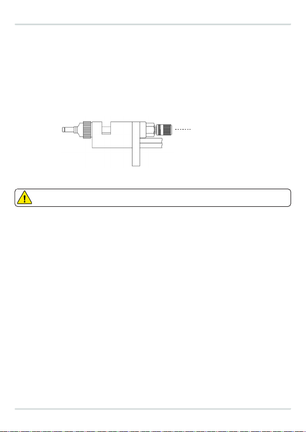
3.4 Setting of the dispensed shot
Pin stroke adjustment determines the amount of fluid delivered.
> Version with micrometric adjustment:
To adjust the travel, act on the adjustment knob at the top of the valve.
Rotate clockwise to decrease the stroke and consequently the amount of adhesive.
Turning clockwise, reaching the end of the stroke the valve will be fully closed, so it will not flow fluid.
Rotate counterclockwise to increase the stroke and then the amount of fluid.
3.5 Amount of the shot
Adjusting the amount of material (fluid) is determined by:
> Fluid pressure
> Needle stroke adjustment
> Valve opening time
Acting on these factors, you can adjust the amount of material you want.
Do not tighten the needle setting too firmly to avoid damaging the needle and nozzle.
Adjustment knob
360° SPRAY VALVE FOR INTERNAL DAS 50N

6.1 Overall dimensions DAS 50 / DAS 50N
The size of the enclosure depends on the type of
extender used and its length.
Download 3D models from our web-site.
Dimensions refer to the 15mm extension.
5 TROUBLESHOOTING
5.1 Problems and solutions
The search for defects in the operation should be performed only by personnel qualified respecting the safety rules
in force.
6 SPARE PARTS AND DIMENSIONS
Installation and maintenance guide
PROBLEM POSSIBLE CAUSE SOLUTION
Nothing or little fluid Valve does not receive the command Check valve (solenoid valve) control. Perform
a manual test.
The pressure of the fluid is too low
or absent. Check the fluid supply pressure and, if
necessary, increase it.
The nozzle is clogged
Unscrew and clean the nozzle.
The filter is dirty (if present) Wash or replace the filter.
A tube is bent Check the status of the fluid supply pipes
Insufficient drive pressure Check drive pressure (5-7 bar)
Fluid residues present in the system Clean the system with water
Fluid out of the compass O-ring or shaped gasket on the damaged
valve body Replace O-ring or shaped gasket
Fluid flow between valve
body and fixing plate O-ring on the damaged dam reservoir Replace the O-ring of the hub
The nozzle dries even if
the valve is not piloted Presence of dirt in the nozzle Clean or replace the nozzle.
The valve opens late Insufficient drive pressure Check drive pressure 5-7 bar
O-ring on the damaged spike Replace the O-ring on the pin
Splashed irregularly Insufficient spraying pressure Check spraying pressure
(0,1…2,5 bar)
Dirt in the air cap Clean the air cap
black
air drive
transparent
material
blue
nebulization

pag.7
360° SPRAY VALVE FOR INTERNAL DAS 50N
5.2 Esploso ricambi DAS 50 N
POS CODE DESCRIPTION
10003.36000009 MICROMETRIC REGULATION COMPLETE
20003.000200 PRESSURE SPRING
30003.36000006 FIXING PLATE
40003.010407 BLUE HOSE (ATOMIZING AIR)
50003.050407 CLEAR HOSE (FLUID)
60003.140407 BLACK HOSE (COMMAND AIR)
70003.36000011 HOSE HOLDER
80003.000901N O-RING
9NEEDLE COMPLETE
0003.84150206 9.1 NEEDLE COMPLETE 20 mm
0003.84150306 9.2 NEEDLE COMPLETE 30 mm
0003.84150506 9.3 NEEDLE COMPLETE 50 mm
0003.84151006 9.4 NEEDLE COMPLETE 100 mm
0003.84152006 9.5 NEEDLE COMPLETE 200 mm
10 0003.0004010 NEEDLE NUT
11 0003.36000028 NEEDLE COLLAR
12 0003.36000005 PISTON
13 0003.000015E O-RING
14 0003.000007E O-RING
15 NEEDLE BASIC
0003.84050206 15.1 NEEDLE BASIC 20 mm
0003.84050306 15.2 NEEDLE BASIC 30 mm
0003.84050506 15.3 NEEDLE BASIC 50 mm
0003.84051006 15.4 NEEDLE BASIC 100 mm
0003.84052006 15.5 NEEDLE BASIC 200 mm
16 0003.36000003 BUSH
17 0003.000010E O-RING
18 0003.30570T VARISEAL
19 0003.36000001 BODY VALVE
20 0003.36000029 PLASTIC COLLAR
21 FLUID OUTLET EXTENDER
0003.85811020 21.1 FLUID OUTLET EXTENDER 20 mm
21.2 FLUID OUTLET EXTENDER 30 mm
21.3 FLUID OUTLET EXTENDER 50 mm
21.4 FLUID OUTLET EXTENDER 100 mm
21.5 FLUID OUTLET EXTENDER 200 mm
22 0003.85791003 AIR CAP
23 0003.85792001 COLLAR
24 0003.060X10E O-RING
25 AIR EXTENDER
25.1 AIR EXTENDER 20 mm
25.2 AIR EXTENDER 30 mm
25.3 AIR EXTENDER 50 mm
25.4 AIR EXTENDER 100 mm
25.5 AIR EXTENDER 200 mm
26 0003.85801000 EXTENDER NOZZLE
GASKETKIT-DAS50N-EV
GASKET KIT COMPLETE
5.3 Lista ricambi DAS 50 N
32 LISTINO RICAMBI 2023
codice codicepos. pos.q.tà q.tàdescrizione descrizione€ €
VALVOLA ELETTROPNEUMATICA SPRAY MZF360 lisno ricambi 2023
1
2
3
4
912
16
17
23
24
25
26
18
19
20
21
22
13
14
14
15
11
10
5
6
7
8
1 C36000009 1 Regolazione micrometrica
completa 57,00
2 CCS000200 1 Molla 6,00
3 C36000006 1 Piastra ssaggio 30,00
4 TBP010407 1 Tubo blu (aria di nebulizzazione) 2,00
5 TBP050407 1 Tubo trasparente (uido) 2,00
6 TBP140407 1 Tubo nero (aria pilotaggio) 2,00
7 C36000011 3 Porta tubo 7,00
8 RNG000901N 3 O-ring� 2,00
9
H84150206
H84150306
H84150506
H84151006
H84152006
1
1
1
1
1
Spillo completo 20 mm
Spillo completo 30 mm
Spillo completo 50 mm
Spillo completo 100 mm
Spillo completo 200 mm
95,00
95,00
95,00
100,00
105,00
10 NT0004010 1 Dado spillo 5,00
11 C36000028 1 Ghiera spillo 6,00
12 C36000005 1 Pistone 8,00
13 RNG000015E 1 O-ring� 2,00
14 RNG000007E 2 O-ring� 2,00
15
H84050206
H84050306
H84050506
H84051006
H84052006
1
1
1
1
1
Spillo nudo 20 mm
Spillo nudo 30 mm
Spillo nudo 50 mm
Spillo nudo 100 mm
Spillo nudo 200 mm
75,00
75,00
75,00
80,00
85,00
16 C36000003 1 Bussola 14,00
17 RNG000010E 1 O-ring� 2,00
18 SHS30570T 1 Guarnizione sagomata� 9,00
19 C36000001 1 Corpo valvola 218,00
20 C36000029 1 Protezione in plasca 1,00
21
H85811020
H85811030
H85811050
H85811100
H85811200
1
1
1
1
1
Prolunga prodoo 20 mm
Prolunga prodoo 30 mm
Prolunga prodoo 50 mm
Prolunga prodoo 100 mm
Prolunga prodoo 200 mm
78,00
78,00
78,00
83,00
88,00
22 H85791003 1 Cappuccio aria 48,00
23 H85792001 1 Ghiera 9,00
24 RNG060X10E 1 O-ring� 2,00
25
H85801020
H85801030
H85801050
H85801100
H85801200
1
1
1
1
1
Prolunga aria 20 mm
Prolunga aria 30 mm
Prolunga aria 50 mm
Prolunga aria 100 mm
Prolunga aria 200 mm
33,00
33,00
33,00
38,00
43,00
26 H85801000 1 Terminale prolunga 201,00
KGN000210 1 Kit guarnizioni� 25,00

We reserve the right to modify at any time, without notice, the specifications, dimensions and weights in this manual.
The illustrations are not binding.
DAV TECH SRL Via Ravizza, 30 - 36075 Montecchio Maggiore (VI) - ITALY - Tel. 0039 0444 574510 - Fax 0039 0444 574324
Table of contents
Other DAV TECH Control Unit manuals

DAV TECH
DAV TECH DA 400 EV Product manual

DAV TECH
DAV TECH DA 400 Product manual

DAV TECH
DAV TECH DAS 90 Product manual

DAV TECH
DAV TECH DA 400 EVO Product manual

DAV TECH
DAV TECH DAS 30 Product manual

DAV TECH
DAV TECH DA 600 Product manual

DAV TECH
DAV TECH DAV 300 MAN Product manual

DAV TECH
DAV TECH DA 250 Product manual

DAV TECH
DAV TECH DAV 150 Product manual
Popular Control Unit manuals by other brands


FUEL MASTER
FUEL MASTER AIM 2 installation manual

DH Instruments
DH Instruments PK-7600-VAC-VENT installation instructions

Aumuller
Aumuller M-COM Click Assembly and commissioning instructions

CORNING
CORNING EDGE Series manual

Silicon Laboratories
Silicon Laboratories Si8410 manual

Zator
Zator MZB200 User and maintenance manual