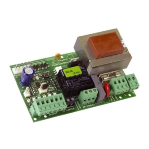
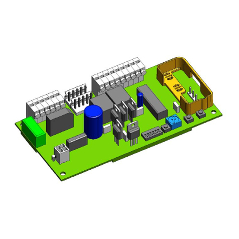
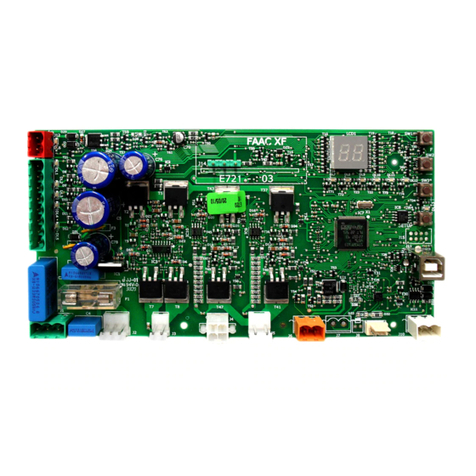
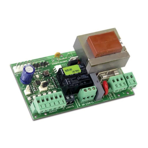
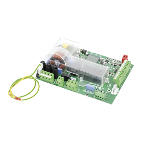
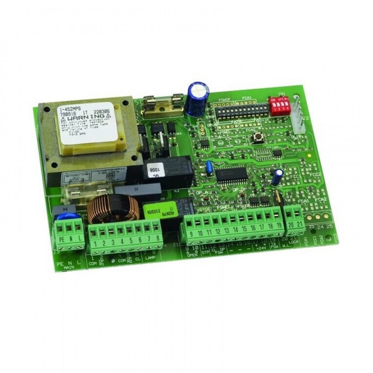
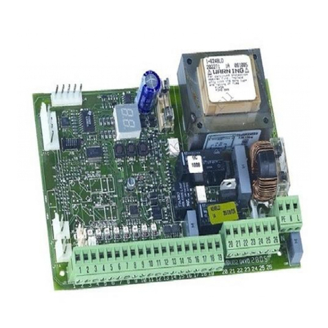
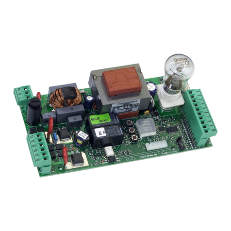
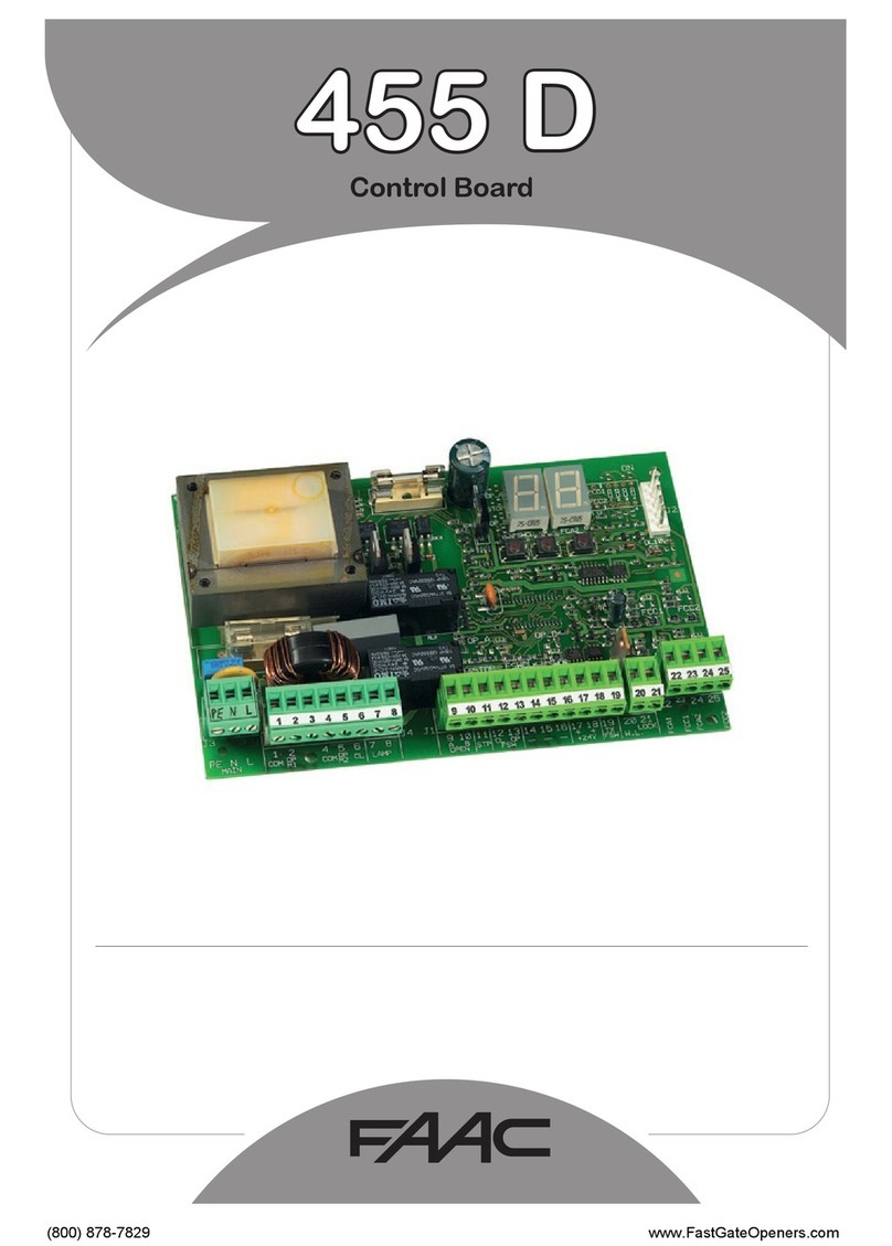
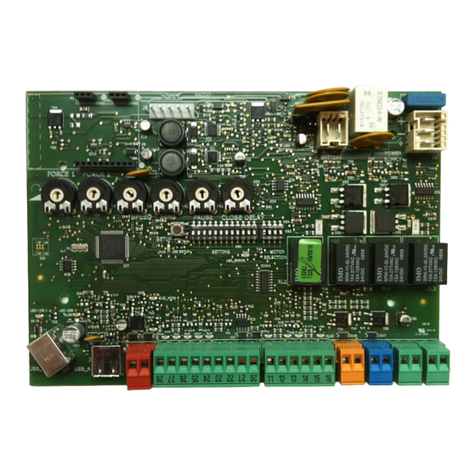
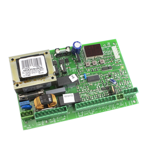
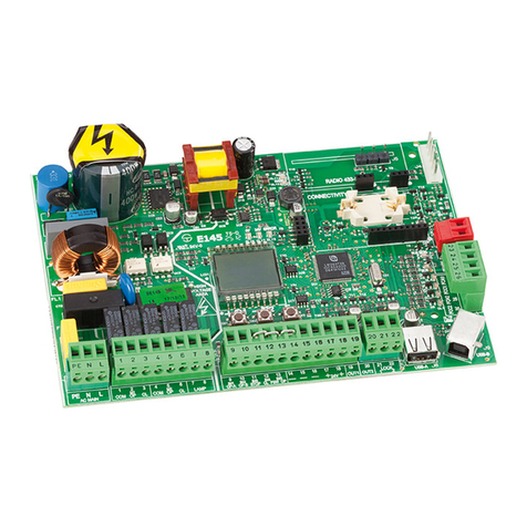
FAAC 844T User manual

carta riciclata 100%
per la natura for nature
recycled paper 100%
ist umweltfreundlich
100% Altpapier
para la naturaleza
100% papel reciclado
papier recyclé 100%
pour la nature voor de natuur
100% kringlooppapier
844T
844T

7
1) ATTENTION!Toensurethesafetyofpeople,itisimportantthatyouread
all the following instructions. Incorrect installation or incorrect use of
the product could cause serious harm to people.
2) Carefullyreadtheinstructionsbeforebeginningtoinstalltheproduct.
3) Donot leavepackingmaterials(plastic,polystyrene,etc.) within reach
of childrenas suchmaterials are potential sources of danger.
4) Storetheseinstructionsfor futurereference.
5) This productwasdesigned andbuiltstrictly for theuseindicated in this
documentation. Any other use, not expressly indicated here, could
compromisethegoodcondition/operationoftheproductand/orbea
sourceofdanger.
6) FAACdeclinesallliabilitycausedbyimproperuseoruseotherthanthatfor
whichtheautomatedsystemwasintended.
7) Donotinstalltheequipmentinanexplosiveatmosphere:thepresenceof
inflammablegasorfumesisaseriousdangertosafety.
8) ThemechanicalpartsmustconformtotheprovisionsofStandardsEN12604
andEN12605.
Fornon-EUcountries,toobtainanadequatelevelofsafety,theStandards
mentioned above must be observed, in addition to national legal
regulations.
9) FAAC is not responsible for failure to observe Good Technique in the
constructionoftheclosingelementstobemotorised,orforanydeformation
thatmayoccurduringuse.
10) TheinstallationmustconformtoStandardsEN12453andEN12445.
Fornon-EUcountries,toobtainanadequatelevelofsafety,theStandards
mentioned above must be observed, in addition to national legal
regulations.
11) Beforeattemptinganyjobonthesystem,cutoutelectricalpower.
12) Themainspower supplyoftheautomatedsystemmustbefittedwithanall-
pole switchwithcontactopeningdistanceof3mmorgreater.Useofa6A
thermalbreakerwithall-polecircuitbreakisrecommended.
13) Makesurethatadifferentialswitchwiththresholdof0.03Aisfittedupstream
ofthesystem.
14) Makesurethattheearthingsystemisperfectlyconstructed,andconnect
metalpartsof themeansof theclosuretoit.
15) The safety devices (EN 12978 standard) protect any danger areas
againstmechanicalmovementRisks,suchascrushing,dragging,and
shearing.
16) Useofatleastoneindicator-light(e.g.FAACLIGHT)isrecommendedfor
everysystem,aswellasawarningsignadequatelysecuredtotheframe
structure,inadditiontothedevicesmentionedatpoint“15”.
17) FAACdeclinesallliabilityasconcernssafetyandefficientoperationof
theautomatedsystem,ifsystemcomponentsnotproducedbyFAAC
areused.
18) Formaintenance,strictlyuseoriginalpartsbyFAAC.
19) Donotinanywaymodifythecomponentsoftheautomatedsystem.
20) Theinstallershallsupplyallinformationconcerningmanualoperationof
thesystemincaseofanemergency,andshallhandovertotheuserthe
warningshandbooksuppliedwiththeproduct.
21) Do not allow children or adults to stay near the product while it is
operating.
22) Keepremotecontrolsorotherpulsegeneratorsawayfromchildren,to
preventtheautomatedsystemfrombeingactivatedinvoluntarily.
23) Transitthroughtheleavesisallowedonlywhenthegateisfullyopen.
24) Theusermustnotattemptanykindofrepairordirectactionwhatever
andcontactqualifiedpersonnelonly.
25) Maintenance:checkatleastevery6monthstheefficiencyofthesystem,
particularly the efficiency of the safety devices (including, where
foreseen,theoperatorthrustforce)andofthereleasedevices.
26) Anythingnotexpresslyspecifiedintheseinstructionsisnotpermitted.
WARNINGS FORTHE INSTALLER
GENERAL SAFETY OBLIGATIONS
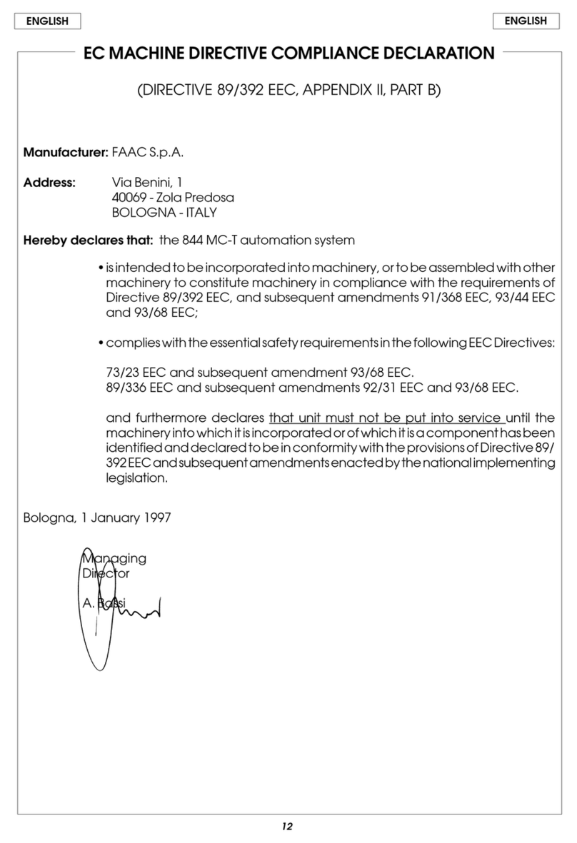
EC DECLARATION OF CONFORMITY
Manufacturer : FAAC S.p.A.
Address: Via Benini, 1 - 40069 Zola Predosa BOLOGNA - ITALY
Declares that: 844 T control board,
• conforms to the essential safety requirements of the following directives:
73/23/EECand subsequentamendment 93/68/EEC.
89/336/EEC and subsequent amendment 92/31/EEC and 93/68/EEC
Additionalnote:
Thisproduct underwenttestsinatypical uniformconfiguration
(all products manufactured by FAAC S.p.A.).
Bologna, 01 January 2005 The Managing Director
A. Bassi

8
F7
TF1
DS1
SW1
F5
J1
J3
LK1
F6
LED J5
RL6
RL7
F2
J4
J2
RL8
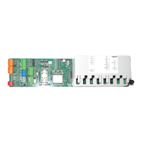
CONTROL BOARD 844 T
Theseinstructionsapplytothefollowingmodel:
844T Electronic control unit
This appliance can be installed in containers mod. E, L and
LM. Beforesecuringthe card inthe container,fit thesupplied
supportfeet(long for mod.E, shortfor modelsL andLM) inthe
3S-holes(Fig.1).
2. ELECTRICAL CONNECTIONS WITH 400V 3ph (N.B.: for connection to 230 V 3ph, see Chapter 8)
Fig. 1
1. TECHNICAL SPECIFICATIONS
ylppusrewoP ).zH05%01-%6+(hp3.caV032 ).zH05%01-%6+(N+hp3.caV004
daolxamrotoM .wK3,1
ylppusrewopseirosseccA .cdV42
daolxamseirosseccA .Am005
ylppusrewopthgilgininraW ).ttaW5xam(.caV42
egnarerutarepmeT C°55+C°02-
sesuF )1.baT(7F,6F,5F,2F
sgulptif-kciuQ sreviecerPRrosdracgnidoced
stupnI /NEPOLAITRAP/NEPO /ECIVEDYTEFASERUSOLC/POTS SROSNES-TIMIL
stuptuO
thgilginraw thgilhsalf rotom seirossecca.cdV42otylppusrewop
gnimmargorP
06-03-51-01-5(emitesuap ).ces081-021 C/B/2E/1E/2S/1S/2A/1Ascigol gnihsalf-erp
gnikarbrotoM dexif
gnimitytefaS .ces552
7F-6F-5F )sesufylppusrewop(diparV052/A523x3,61FesuF
2F )seirossecca(diparV052/A6,102x52FesuF
1WS nottub-hsupTESER
1SD sehctiwsorcimgnimmargorP
DEL ACF,CCF,WSF,POTS,B,AsDELgnillangissutatstupnI
1J sreviecerPR/sdracgnidocedrofgulptif-kciuQ
2J seirossecca/stupnirofdraoblanimretegatlovwoL
3J )W06xam~V032(draoblanimrettuptuothgilhsalF
4J draoblanimrettuptuorotoM
5J draoblanimrettupniylppusrewopeniL
1KL tcatnoceerfthgilgninrawrofegdirB
7LR-6LR yalerrotoM
8LR yalergnikarB
Tab. 1 - 844 T CONTROL UNIT COMPONENTS

9
844MPS
69
8
7
24V~ 5W max
9
8
2A max
MINIDEC
SL/DS
PLUS
844MPS
DECODER
SL/SLP/DS
844MPS
844 T
844 T
844 T
!!
!!
!
3. DESCRIPTION
3.1. J1 PLUG
The J1 plug is used for rapid connection of cards MINIDEC,
DECODER, RP RECEIVERS (Fig. 3, 4, 5)
Install by fitting the accessory cards so that their components
side faces the inside of the 844 T electronic appliance.
Insert and remove the cards after cutting power.
3.2. TERMINAL BOARD J2 (low voltage)
1 = OPEN A (N.O.) – Total opening
This is any pulse generator with N.O. contact which, when
activated, produces a gate opening movement. In A, E
and S logics, it commands both opening and closing.
To install several Open A devices, connect N.O. contacts
in parallel.
2 = OPEN B (N.O.) – Opening for pedestrians / Closing
This is any pulse generator with N.O. contact which, when
activated in logics A, E and S, produces a gate opening
movement for pedestrians. In B and C logics, it commands
a closing movement.
To install several Open B devices, connect N.O. contacts
in parallel.
3 = STOP command (N.C.)
This is any device (e.g. a push-button) which, by opening
a contact, stops gate movement.
To install several stop devices, connect the N.C. contacts
in series.
!If Stop devices are not connected, link the input to the
common contact (terminal 5) via a jumper.
4 = FSW closing safety devices contact (N.C.)
Safety devices are all devices (photocells, sensitive edges,
magnetic coils) with N.C. contact, which, if there is an
obstacle in the area they protect, operate to interrupt
gate movement. The purpose of the closing safety devices
is to protect the gate movement area during closing.
If the safety devices are tripped during closure, gate
movement is reversed,whereas they have no effect during
opening. If used when the gate is open or pausing, closing
safety devices prevent its closing.
To install several safety devices,connect the N.C. contacts
in series.
!!
!!
!If closing safety devices are not connected, link this
input to the common contact (terminal 5) via a jumper.
5 = Common contact for commands
6 = Negative of accessories power supply
7 = 24 Vdc (+) power supply for accessories
Max load of accessories is 500 mA.
To calculate absorption values, refer to the instructions
for individual accessories.
9 = Warning light output (24 Vac)
The maximum load of the warning light is 5 W.
For instructions on operation of the warning light, consult
microswitch programming.
!!
!!
!If you cut out jumper LK1, you obtain a voltage free
contact between terminals 8 and 9 (see Fig. 6).
10 = 24 Vdc (+) power supply for inductive limit switch
11 = Limit switch common contact
12 = Opening limit switch (N.C.)
13 = Closing limit switch (N.C.)
3.3. TERMINAL BOARD J3 (high voltage)
Terminal board for connecting flashlight (max 60W).
3.4. TERMINAL BOARD J4 (high voltage)
Terminal board for connection of motor.
3.5. TERMINAL BOARD J5 (high voltage)
Terminal board for supplying power of 400V 3ph + Neutral - 50 Hz
(see Fig. 1) or 230V 3ph - 50 Hz (see Fig. 8).
Connect the yellow-green earth cable as shown in Fig. 7.
Fig. 6
COMPLETELK1 INTERRUPTEDLK1
(Freecontact)
Fig. 7
Fig. 3 Fig. 4 Fig. 5

10
3.6. SIGNALLINGLEDs
6 LEDs are fitted on the card, indicating status of terminal board
inputs:
LED LIGHTED
= contact closed
LED OFF
= contact open
4. PROGRAMMING
To program operation of automation, use the microswitches as
shown below.
1 2 3 4 5 6 7
Operation of warning light
Gatestatus
SW6 Closed Opening/Open Closing
ON
OFF
Light
Flashing
Light
Off Steadylight
Pre-flashing (2)
SW7
Yes ON
No OFF
Logic SW1 SW2 SW3
E1 ON ON ON
B OFF ON ON
S2 ON OFF ON
E2 OFF OFF ON
A1 ON ON OFF
C OFF ON OFF
S1 ON OFF OFF
A2 OFF OFF OFF
Pause time (sec) (1)
Logic
A1-A2-S2 S1 SW4 SW5
515ONON
10 30 OFF ON
30 60 ON OFF
120 180 OFF OFF
ON
OFF
(1) Pause times include pre-flashing if any
(2) Pre-flashing begins 5” before every movement.
!YoumustpresstheRESETpush-buttonaftereveryprogram-
mingjob.
4.1. FUNCTION LOGICS
The following are available:
A1/A2 = “Automatic” S1/S2 = “Safety”
E1/E2/B = “Semi-automatic” C = “Dead man”
Operation of automation in the different logics is indicated in
Tables 3 - 4 - 5 - 6 - 7 - 8 - 9 - 10.
4.2. PAUSE TIME
Pause time is waiting time in open position before re-closing
when an automatic logic was selected.
Pause times include pre-flashing if any
4.3. OPERATION OF WARNING LIGHT
Used to change the appearance of the warning light at closing
by making it flash.
4.4. PRE-FLASHING
Flashlight pre-flashing time of 5 sec before any movement can
be selected. This warns anyone near the gate that it is about to
move.
5. FAULT CONDITIONS
The following conditions cause certain effects to normal opera-
tion of automation:
햲microprocessor error
햳safety electronic timing tripped (operation is interrupted if
continuous work time exceeds 255 sec. ).
햴limit sensors disconnected (or both engaged)
• Conditions 햲and 햳cause automation to stop and nothing
more.
• Condition 햴causes an alarm situation disabling any activ-
ity:
• Normal operation can be restored only after eliminating the
alarm cause and pressing the RESET push-button (or turning
off power supply momentarily).
• To have this condition signalled, the warning light must be
connected: the alarm is signalled by very rapidly flashing light
(0.25 sec).
NB.: The status of the LEDs while the gate is closed at rest are
shown in bold.
DELDETHGILFFO
ANEPO
evitcadnammoC evitcanidnammoC
BNEPO
evitcadnammoC evitcanidnammoC
POTS
evitcanidnammoC evitcadnammoC
WSF
gnitarepotonsecivedytefaS gnitareposecivedytefaS
CCF
eerfrosnestimilgnisolC degagnerosnestimilgnisolC
ACF
eerfrosnestimilgninepO degagnerosnestimilgninepO
Tab. 2 - STATUS OF LEDS

11
7. ROTATION DIRECTION CHECK
1) Releasetheoperator,takeitmanuallytomid-travelandre-
lock it.
2) PowerupthesystemandthenpresstheRESETpush-button.
3) GiveanOpencommandtotheoperator,checkifthegate
movesinopening direction andthenpresstheRESETpush-
button to stop the leaf moving.
4) Ifrotationdirectionisincorrect, changeover wiringofcables
T1and T3 oftheelectric motor.
6. LIMIT SENSORS CONNECTION CHECK
1) Manually take the gate toward opening position, and
checkif,withtheleaf open,theFCCLEDislightedandthe
FCALEDisoff.
2) Manuallytakethegatetowardclosingposition,andcheck
if,with theleaf closed, theFCA LED islightedand theFCC
LEDisoff.
2) IftheLEDsareinverted,changeoverthecablesconectedto
trminals 12 and 13.
Fig. 8
8. ELECTRICAL CONNECTIONS WITH 230V 3ph
To connect the 844 T appliance to a 3-phase 230 V mains, ob-
serve the diagram in Fig. 8.
N.B.: The electric motor of the gearmotor must be 230V 3-phase.

12
"1A"cigoLSESLUP
SUTATSSETAG)1(BNEPO-ANEPOPOTSSECIVEDYTEFAS
DESOLC
retfasesolcdnasnepO )2(emitesuap tceffeoNtceffeoN
ESUAPNONEPO
)3("5retfasesolc-eRtnuocehtspotStnemegagnesidlitnuesuapsezeerF
GNISOLC
noitomsesreveRspotSnoitomsesreveR
GNINEPO
tceffeoNspotStceffeoN
DEPPOTS
)2(sesolc-eRtceffeoNtceffeoN
Tab. 3 - LOGIC A1 (AUTOMATIC)
Tab. 5 - LOGIC S1 (SAFETY)
"1S"cigoLSESLUP
SUTATSSETAG)1(BNEPO-ANEPOPOTSSECIVEDYTEFAS
DESOLC
retfasesolcdnasnepO )2(emitesuap tceffeoNtceffeoN
ESUAPNONEPO
)3-2(yletaidemmisesolCtnuocehtspotS ,degagnesidnehw ”5retfasesolc-er
GNISOLC
noitomsesreveRspotSnoitomsesreveR
GNINEPO
noitomsesreveRspotStceffeoN
DEPPOTS
)2(sesolc-eRtceffeoNtceffeoN
Tab. 6 - LOGIC S2 (SAFETY PLUS)
"2S"cigoLSESLUP
SUTATSSETAG)1(BNEPO-ANEPOPOTSSECIVEDYTEFAS
DESOLC
retfasesolcdnasnepO )2(emitesuap tceffeoNtceffeoN
ESUAPNONEPO
)3-2(yletaidemmisesolCtnuocehtspotStnemegagnesidlitnuesuapsezeerF
GNISOLC
noitomsesreveRspotS tasesreverdnaspotS )2(tnemegagnesid
GNINEPO
noitomsesreveRspotStceffeoN
DEPPOTS
)2(sesolc-eRtceffeoNtceffeoN
Tab. 8 - LOGIC E2 (SEMI-AUTOMATIC PLUS)
"2E"cigoLSESLUP
SUTATSSETAG)1(BNEPO-ANEPOPOTSSECIVEDYTEFAS
DESOLC
)2(snepOtceffeoNtceffeoN
NEPO
)2(sesolc-eRtceffeoNtceffeoN
GNISOLC
noitomsesreveRspotS sesreverdnaspotS )2(tnemegagnesidta
GNINEPO
spotSspotStceffeoN
DEPPOTS
ytefasnehw(sesolc-eR )snepo-erti,degagnesecived )2( tceffeoNtceffeoN
Tab. 7 - LOGIC E1 (SEMI-AUTOMATIC)
"1E"cigoLSESLUP
SUTATSSETAG)1(BNEPO-ANEPOPOTSSECIVEDYTEFAS
DESOLC
)2(snepOtceffeoNtceffeoN
NEPO
)2(sesolc-eRtceffeoNtceffeoN
GNISOLC
noitomsesreveRspotSnoitomsesreveR
GNINEPO
spotSspotStceffeoN
DEPPOTS
secivedytefasnehw(sesolc-er )2()snepo-erti,degagne tceffeoNtceffeoN
Tab. 9 - LOGIC B (SEMI-AUTOMATIC)
"B"cigoLSESLUP
SUTATSSETAGANEPO)4(BNEPOPOTSSECIVEDYTEFAS
DESOLC
)2(snepOtceffeoNtceffeoNtceffeoN
NEPO
tceffeoN)2(sesolCtceffeoNgnisolcstneverp
GNISOLC
tceffeoNtceffeoNtnemevomspotStnemevomspotS
GNINEPO
tceffeoNtceffeoNtnemevomspotStceffeoN
DEPPOTS
)2(gnineposetelpmoC)2(gnisolcsetelpmoCtceffeoNgnisolcstneverp
Tab. 10 - LOGIC C (DEAD MAN)
"C"cigoL NWODDLEHSLORTNOC YLSUOUNITNOC SESLUP
SUTATSSETAG)5(ANEPO)5dna4(BNEPOPOTSSECIVEDYTEFAS
DESOLC
snepOtceffeoNtceffeoNtceffeoN
NEPO
tceffeoNsesolCtceffeoNgnisolcstneverp
GNISOLC
tceffeoNtnemevomspotStnemevomspotS
GNINEPO
tceffeoNtnemevomspotStceffeoN
DEPPOTS
gnineposetelpmoC setelpmoC gnisolc tceffeoNgnisolcstneverp
Tab. 4 - LOGIC A2 (AUTOMATIC PLUS)
"2A"cigoLSESLUP
SUTATSSETAG)1(BNEPO-ANEPOPOTSSECIVEDYTEFAS
DESOLC
retfasesolcdnasnepO )2(emitesuap tceffeoNtceffeoN
ESUAPNONEPO
)3("5retfasesolc-eRtnuocehtspotS ,degagnesidnehW "5retfasesolc-er
GNISOLC
noitomsesreveRspotS sesreverdnaspotS )2(tnemegagnesidta
GNINEPO
tceffeoNspotStceffeoN
DEPPOTS
)2(sesolc-eRtceffeoNtceffeoN
(1)OPENBinputcommandspartialopening.
(2)Withpre-flashingselected,movementbeginsafter5sec.
(3)Ifthepulseissentduringpre-flashing,countingisrestarted.
(4)OPENBinputcommandsclosing.
(5)Push-buttonmustbekeptpressedtoactivategatemovement. Whenthepush-buttonisreleased,thegatestops.

Le descrizioni e le illustrazioni del presente manuale non sono impegnative. La FAAC si riserva il diritto, lasciando
inalterate le caratteristiche essenziali dell’apparecchiatura, di apportare in qualunque momento e senza
impegnarsi ad aggiornare la presente pubblicazione, le modifiche che essa ritiene convenienti per miglioramenti
tecnici o per qualsiasi altra esigenza di carattere costruttivo o commerciale.
The descriptions and illustrations contained in the present manual are not binding. FAAC reserves the right, whilst
leaving the main features of the equipments unaltered, to undertake any modifications it holds necessary for either
technical or commercial reasons, at any time and without revising the present publication.
Les descriptions et les illustrations du présent manuel sont fournies à titre indicatif. FAAC se réserve le droit
d’apporter à tout moment les modifications qu’elle jugera utiles sur ce produit tout en conservant les caractéristiques
essentielles, sans devoir pour autant mettre à jour cette publication.
Die Beschreibungen und Abbildungen in vorliegendem Handbuch sind unverbindlich. FAAC behält sich das Recht
vor, ohne die wesentlichen Eigenschaften dieses Gerätes zu verändern und ohne Verbindlichkeiten in Bezug auf
die Neufassung der vorliegenden Anleitungen, technisch bzw. konstruktiv/kommerziell bedingte Verbesserungen
vorzunehmen.
Las descripciones y las ilustraciones de este manual no comportan compromiso alguno. FAAC se reserva el
derecho, dejando inmutadas las características esenciales de los aparatos, de aportar, en cualquier momento
y sin comprometerse a poner al día la presente publicación, todas las modificaciones que considere oportunas
para el perfeccionamiento técnico o para cualquier otro tipo de exigencia de carácter constructivo o comercial.
De beschrijvingen in deze handleiding zijn niet bindend. FAAC behoudt zich het recht voor op elk willekeurig
moment de veranderingen aan te brengen die het bedrijf nuttig acht met het oog op technische verbeteringen
of alle mogelijke andere productie- of commerciële eisen, waarbij de fundamentele eigenschappen van de
apparaat gehandhaafd blijven, zonder zich daardoor te verplichten deze publicatie bij te werken.
Timbro del Rivenditore:/Distributor’s Stamp:/Timbre de l’Agent:/ Fachhändlerstempel:/Sello del Revendedor:/Stempel van de dealer:
FAAC S.p.A.
Via Benini, 1
40069 Zola Predosa (BO) - ITALIA
Tel.: 051/61724 - Fax: 051/758518
www.faac.it
FAAC per la natura
• La presente istruzione è realizzata al 100% in carta riciclata.
• Non disperdete nell'ambiente gli imballaggi dei componenti dell'automazione bensì selezionate
i vari materiali (es. cartone, polistirolo) secondo prescrizioni locali per lo smaltimento rifiuti e le
norme vigenti.
FAAC for the environment
• The present manual is produced in 100% recycled paper
• Respect the environment. Dispose of each type of product packaging material (card, polystyrene)
in accordance with the provisions for waste disposal as specified in the country of installation.
FAAC der Umwelt zuliebe
• Vorliegende Anleitungen sind auf 100% Altpapier gedruckt.
• Verpackungsstoffe der Antriebskomponenten (z.B. Pappe, Styropor) nach den einschlägigen
Normen der Abfallwirtschaft sortenrein sammeln.
FAAC écologique
• La présente notice a été réalisée 100% avec du papier recyclé.
• Ne pas jeter dans la nature les emballages des composants de l’automatisme, mais sélectionner
les différents matériaux (ex.: carton, polystyrène) selon la législation locale pour l’élimination des
déchets et les normes en vigueur.
FAAC por la naturaleza.
• El presente manual de instrucciones se ha realizado, al 100%, en papel reciclado.
• Los materiales utilizados para el embalaje de las distintas partes del sistema automático (cartón,
poliestireno) no deben tirarse al medio ambiente, sino seleccionarse conforme a las prescripciones
locales y las normas vigentes para el desecho de residuos sólidos.
FAAC voor de natuur
• Deze gebruiksaanwijzing is gedrukt op 100% kringlooppapier.
• Laat de verpakkingen van de componenten van het automatische systeem niet in het milieu
achter, maar scheidt de verschillende materialen (b.v. karton, polystyreen) volgens de plaatselijke
voorschriften op de afvalverwerkingen en de geldende normen.
732367 - Rev. B
carta riciclata 100%
per la natura for nature
recycled paper 100%
ist umweltfreundlich
100% Altpapier
para la naturaleza
100% papel reciclado
papier recyclé 100%
pour la nature voor de natuur
100% kringlooppapier
Table of contents
Other FAAC Control Unit manuals
Popular Control Unit manuals by other brands

Hitachi
Hitachi Relion 650 Series Technical manual

Agilent Technologies
Agilent Technologies SD-1 user manual

Leviton
Leviton RENOIR II Series Installation

Panasonic
Panasonic PAN9026 Developer's guide

HPE
HPE Synergy D3940 Product End-of-Life Disassembly Instructions

Gemalto
Gemalto Cinterion BGS2-W miniPCIe Hardware interface description