Gas Heat
Fan On by Plenum
Sw 2 OFF - Sw 3 ON
Reversing Valve
In Cooling
Sw 2 ON - Sw 3 OFF
Reversing Valve
In Heating
Sw 2 ON - Sw 3 ON
On
On
1 2 3 4 5 6
1 2 3 4 5 6
Electric Heat
Fan On with Heat Call
Sw 2 OFF - Sw 3 OFF
On
On
1 2 3 4 5 6
1 2 3 4 5 6
Understanding the Mode of Operation
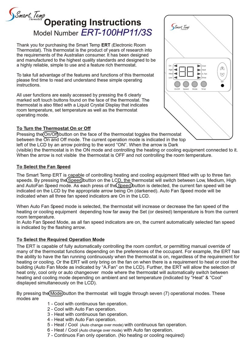
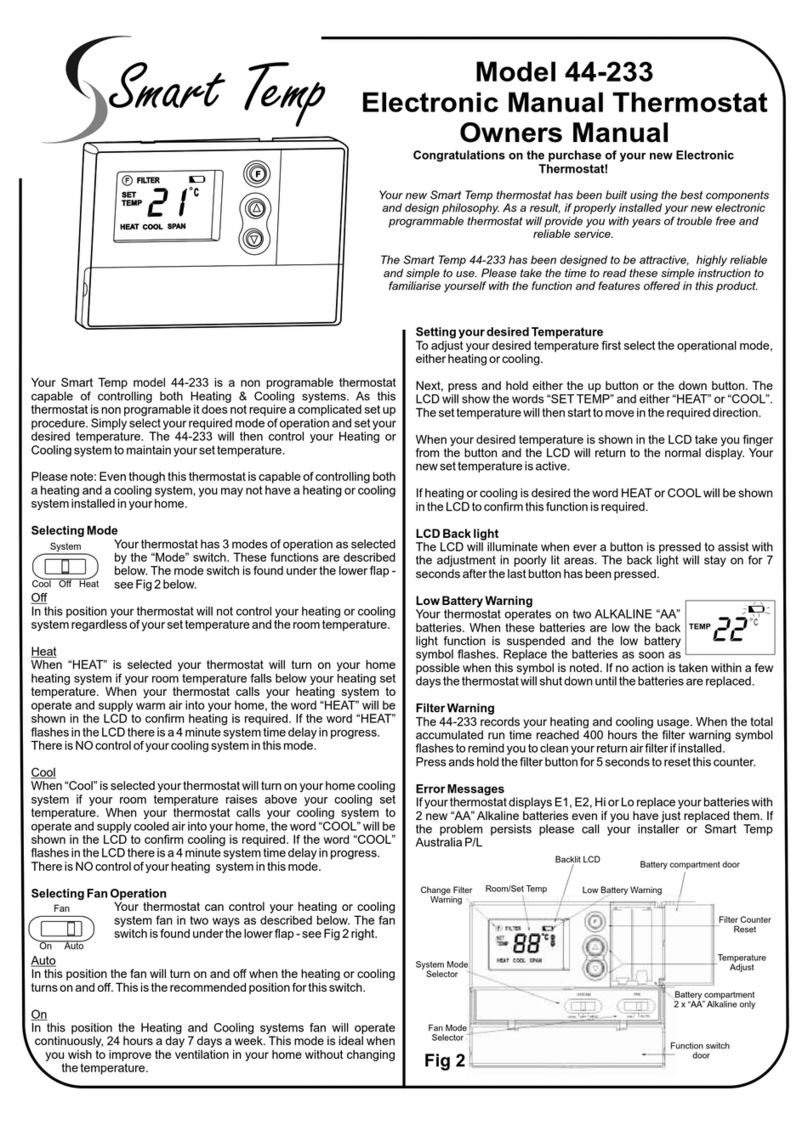
To Adjust the Set (or desired) Room Temperature
Setting the Mode of Operation
Your SMT thermostat will automatically control your Heating system,
your cooling system and the fan for the heating and cooling system.
Most users will prefer to let the SMT operate fully automatically, switching
between heating and cooling modes to maintain the comfort levels you
have previously set. Some uses however may wish to manually switch
between heating and cooling modes.
By using the “Select” button, the various operational modes such as
Heating only or Cooling only or Auto mod can be simply adjusted.
The various modes are described below
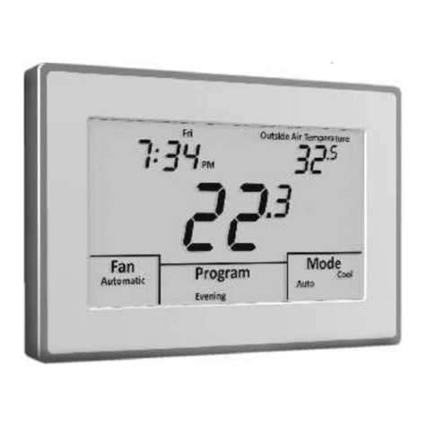
When no buttons are pressed, the LCD indicates the current room
temperature. When the up (+) or down (-) buttons is first pressed the LCD
will flash rapidly and indicate the Set (or desired) room temperature. The
word “SET” will also be displayed in the LCD to confirm the set temperature
is being adjusted.
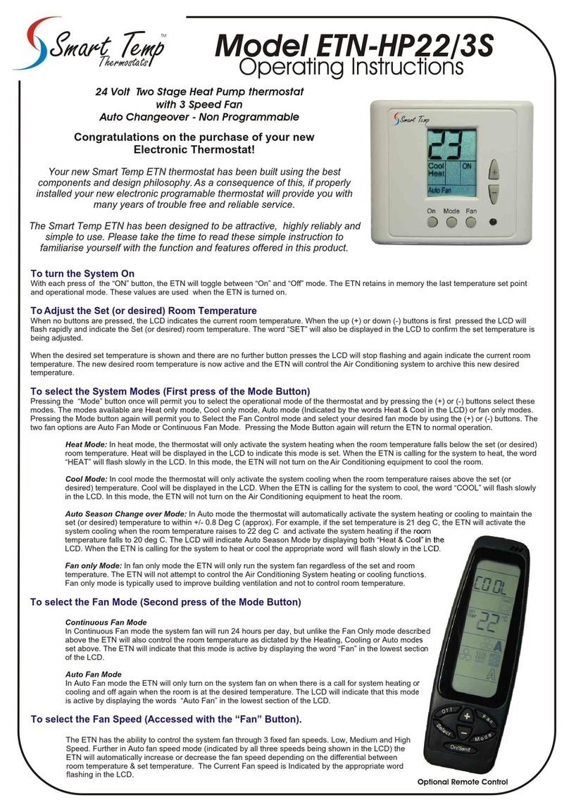
Heat Only Mode: In heat mode, the thermostat will only activate
the system heating when the room temperature falls below the
set (or desired) room temperature. Heat will be displayed in the
LCD to indicate this mode is set. When the SMT is calling for the
system to heat, the word “HEAT” will flash slowly in the LCD. In
this mode, the SMT will not turn on the cooling system regardless
of how warm the room becomes.
Cool Only Mode: In cool mode the thermostat will only activate
the system cooling when the room temperature raises above the
set (or desired) temperature. Cool will be displayed in the LCD.
When the SMT is calling for the system to cool, the word “COOL”
will flash slowly in the LCD. In this mode, the SMT will not turn on
the heating system regardless of how cool the room becomes.
Auto Season Change over Mode: In Auto mode the thermostat
will automatically activate the system heating or cooling to
maintain the set (or desired) heating and cooling temperatures.
The LCD will indicate Auto Season Mode by displaying both
“Heat & Cool” in the LCD. When the SMT is calling for the system
to heat or cool the appropriate word will flash slowly in the LCD.
Fan only Mode: In fan only mode the SMT will only run the
system fan regardless of the set and room temperature. The SMT
will not attempt to control the Air Conditioning System heating or
cooling functions.
Fan only mode is typically used to improve building ventilation
and not to control room temperature.
Continuous Fan Mode
In Continuous Fan mode the system fan will run continiosly when
the Start time has been reached, and remain running until the
Stop time is reached. Unlike the Fan Only mode described above
the SMT will also control the room temperature as dictated by the
Heating, Cooling or Auto modes set above. The SMT will indicate
that this mode is active by displaying the word “Fan” in the LCD.
Auto Fan Mode
In Auto Fan mode the SMT will only turn on the system fan on
when there is a call for system heating or cooling and off again
when the room is at the desired temperature. The LCD will
indicate that this mode is active by displaying the words “Auto
Fan” in the LCD.
Like the programming steps previously explained, adjusting the various
operational modes are accomplished equally as simply and with a minimum
of button presses.
Step 1: Pressing the “Select Button” once will enter the
mode selection menu. The LCD will look similar that shown
in Diag 5.
Pressing the “+” or “-” buttons will permit you to toggle
between Fan only mode, cool only mode, Heat only mode
or Auto Mode ( Heat/Cool Displayed).
Step 2: Pressing the “Select Button” again will permit you
to select either Fan or Auto Fan modes with the “+” & “-”
buttons. Diag 6 shows a typical LCD.
Pressing the “select” button again returns the SMT to
normal mode. The new settings will now take effect.
Advanced Functions
After Hours 2 Hour Timer
Key Board Lock
Manual Mode
Advanced Installer Functions
Temperature Control limits
Calibration Offset
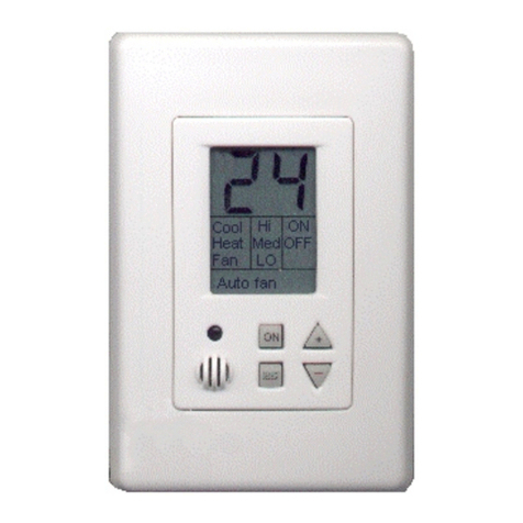
The SMT-310 has an inbuilt after hours timer fitted, tapping the On/Off button
will activate the 2 Hour after hours run on time period.
When the timer is active, the word “STOP” will slowly flash in the LCD to
indicate this function is set.
Your SMT-310 has the ability to lock the keyboard from un authorised
tampering. Pressing and holding the mode button for 15~20 seconds will result
in the SMT LCD to show the word “UNLOC”. Continuing to hold the mode
button will change this to read “LOC”. At this stage the thermostat key board
will be locked ( EXCEPT the ability to activate run on timer).
To unlock repeat this process.
Pressing and Holding the PROG button for 20 seconds will toggle the SMT-310
between Programmable mode (as previously described) and Manual Mode
(No time clock control)
The SMT-310 also has a number of software options that can be set by
accessing the installer menu. To enter the installer menu set the HEATING
temperature to 10c and then press and hold the select button for 10 seconds.
Once in the installer menu the LCD will change and show the word “COOL”
and a number, such as “COOL 05” (default). This is a control value that
overrides the user set temperature and is the lowest temperature the
thermostat will control too. Adjust this value if necessary with the temp + or -
buttons. Tap the select button and now the LCD will change and display the
word “HEAT” and a number, such as “HEAT 30 (default). This is a control value
that overrides the user set temperature and is the Highest temperature the
thermostat will control too. Adjust this value if neccessary with the temp + or -
buttons.
(For example, by setting a COOL value of 19, and a HEAT value of 24 regardless of
where the user sets there preferred heating and cooling set temperatures, the SMT
will limit the control range of the Air Conditioning system to between 19 & 24c).
Tap the select button again to move to the next option.
Once you have set the temperature control limits above (if required), the next
option permits the adjustment (calibration) of the temperature sensor. The LCD
will show “OFFS 0” (default). This value can be adjusted +/- 3c. Permitting you
to add or subtract up to 6 deg from the temperature sensor.
Tap the select button to exit this menu.
22
Cool
Heat
C
Diag 5
Diag 6
23
Auto
Fan
C
Wiring Diagrams and Dip Switch Configuration
G
G
Y1
Y1
Y2
Y2
W1
B/O
W2
W2
C
C
R
R
Com
Com
24Vac
Supply
24Vac
Supply
T
T
T
T
Remote
Sensor
Remote
Sensor
Heat 1
Reversing Valve
Active
Active
Neutral
Neutral
Fan
Fan
Relay Common
Relay Common
Cool 1
Compressor 1
Cool 2
Compressor 2
Heat 2
Auxiliary Heat
Heat Cool Connection
Heat Pump Connection
On On
1 2 3 4 5 6 1 2 3 4 5 6
Remote Temp Sensor
Sw 1 & 6 Off -Sw 5 On
Sw4 OFF = Delay On
Sw4 On = Delay OFF
Sensor Configuration 3 Min Comp Delay
On
1 2 3 4 5 6
Internal Temp Sensor
Sw 1 & 6 On - Sw5 Off
NOTE: Black Denotes Switch Position.
Switches shown in grey do not apply to the function described
Due to continual product improvement, these specifications are subject to change without notice
REV0705PS
Smart Temp Australia Pty Ltd
19 Indra Road Blackburn South 3130 Phone:(03) 9899 6455 Fax (03) 9899 6454
www.thermostat.com.au
Link must be installed for 24V Switching
Link must be installed for 24V Switching


