manuals.online logo
Brands
  1. Home
  2. •
  3. Brands
  4. •
  5. Smart temp
  6. •
  7. Thermostat
  8. •
  9. Smart temp SMT-710 User manual

Smart temp SMT-710 User manual

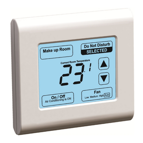
SMT-710 Manual Thermostat with Zone Control
Current Room Temperature
Zone 1
Zone 1
Zone 1
OFF ON AUTO
OFF ON AUTO
OFF ON AUTO
HEAT COOL
HEAT COOL
HEAT COOL
Fan
Fan
Zone 2
Zone 2
Low Medium High Auto
.
.
Fault
Fault
Set your desired temperature
SELECTED
SELECTED
SELECTED
SELECTED
SELECTED
Room
Room
Unoccupied
Unoccupied
ON
ON
Set point
Set point
limit
limit
reached.
reached.
Ventilation
Fan
Low Medium High Auto
ONVentilation
Ventilation
Installer
Mode
Installer
Mode
C
C
F
F
Thank you for the purchase of the Smart Temp
SMT-710 Zone Control Thermostat.
Please take the time to read and understand
this manual so that you may take advantage
of the many features this thermostat may offer
Fan Speed
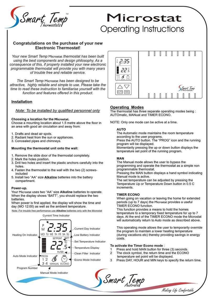
The lower left corner of the display
Controlling the Fan Speed and Mode.
Turning your Thermostat On and OFF.
The SMT-710 can control a single or multi speed fan
system. This capability will be setup by your installer to
match the capability of the Air Conditioning system that
it is controlling.
controls the mode selection, depending
The SMT-710 can also control multi-fan speed systems
where you can either manually select between Low,
Medium and High fan speed or let the SMT-710
automatically select the best fan speed based on how
far the room temperature is from the set temperature.
If set for Heat and Cool mode, a maximum heating and
cooling set point limit may be imposed. Text and a chirp
will be given when this limit is reached.
Simply tap the fan button to cycle through all available
speeds if this function is enabled.
Fan Mode
If the text Heat or Cool is flashing then your SMT-710 is
requesting that function from your air conditioning
system.
on how your installer has set your SMT-710 up you will
be given the option of selecting On and Off with a single
set point (with a preset differential between the heating
and cooling) or selecting individual heating and cooling
modes, each with individual heating and cooling set
points.
Press and hold the fan button to select Fan On Mode -in
3 fan speed mode or tap in single fan speed mode. In
this mode the fan will run continuously regardless of the
heating or cooling. Press and hold (or tap) again to
return to Fan Auto mode where the fan will turn on and
off with the heating and cooling.
Your installer many have set a temperature control limit,
where the range of temperature adjustment may be
restricted. Text showing the limit has been reached will
be shown on the display accompanied by a few beeps.
its ability to manage two independent zones. These
zones are identified as either Zone 1 (The location of
the wall Controller) and Zone 2. If the zone is shown as
“selected” then conditioned air will be sent to this area
and the air conditioning will turn on and off to maintain
this zones temperature.
Single Sensor Zone Control
Limit Control
Zone Control
Setting your desired Temperature.
The display will show you your current room
temperature along with some Up/Down buttons. When
you tap either of the up down button the display will
change and show you the set temperature for the
currently selected mode, being the Heat set point in
Heat only mode and the Cool set point in Cool only
mode or the single set point in Auto or On mode.
Twin Sensor Zone Control
One of the strengths of the SMT-710 is
(Note, In single set point mode your installer will have
defined a “Dead Band” of a few degree either side of
the internal heat and cool set points where the heating
or cooling is not needed.
When the SMT-710 detects the Zone 2 sensor has been
installed, it will control both Zone 1 and Zone 2 to
ensure both zones temperature is maintained to the
desired value. This may mean that conditioned air may
automatically be sent to Zone 2 only (for example) if
zone 2 needs additional heating or cooling to reach the
desired set point. The Air Conditioning system will treat
both zones Independently.
Room Temperature Display - Twin sensor
The SMT-710 will display the Zone 1 temperature when
ever Zone 1 only is selected or if Zone 1 and Zone 2 is
selected. If Zone 2 only is selected the SMT-710 will
display Zone 2 temperature.
Note, If at anytime you wish to see the Zone 2 temperature, press and
hold the Zone 2 button for 2 seconds and the display will go blank
except for the Zone 2 button and the room temperature as measured
in Zone 2. The display will return to normal after 4 seconds.
If the SMT-710 does not have the optional Zone 2
temperature sensor fitted, then it will assume both Zone
1 temperature and Zone 2 temperature is the same - as
measured by the wall controller in Zone 1. The air
conditioning will turn on and off to maintain the current
set point.
Smart Temp
Unit 20 / 1488 Ferntree Gully Rd Knoxfield Vic Aust 3180
www.smarttemp.com.au www.thermostat.com.au
+61 3 97630094 [email protected]
Ver 2.2
Installation
Wiring the wall controller to the unit control card requires 4
wires, 24V Active, 24V common Data A and Data B. The wall
controller and the unit control card are labelled identically,
being R C A B. 4 wires need be used of 0.2mm diameter -
ideally screened but not essential for short runs. An external
24VAC power supply should be used and connected to
either the wall controller or Unit Control Card (12V DC can
also be used, +12 to R and -12 to C).
The SZ-PS power supply is suitable.
Relay Common
Assignable Relay
Low Fan (or single fan)
Medium Fan
HighFan
Zone 1 Damper Close
Zone 1 Damper Open
Zone 2 Damper Close
Zone 2 Damper Open
Zone Common
Comp / Cool Normally Closed
Comp / Cool Normally Open
Heat / R-Valve Normally Closed
Heat / R-Valve Normally Open
24 VAC Active (12V+)
24 VAC Common (12v-)
Data A
Data B
0V / Common
0V / Common
0V / Common
0-10V Heat
0-10V Cool
0-10V Fan
Assignable Input
Zone 2 Temp Sensor
Zone 2 Temp Sensor
Dip Switch Settings (Sw 1, 2,3 &5 on by Default)
Switch
1
2
3
4
5
6
7
8
Function
Fan Speeds
Equipment Type
HP/HC Mode
Not Used
Comp Delay
Not Used
Ventilation Mode
Zone Enable
Off
Single Speed
Heat Cool
Gas Heat / O
Off
Off
Off
On
3 Speed
Heat Pump
Electric Heat / B
On - 5 Min
On
On
Note. Switch 3 function is based on the position of switch 2.
Dip 2 OFF (Heat - Cool Mode) DIP 3 controls the fan mode (Electric or Gas Heat Fan).
DIP 2 ON (Heat Pump Mode) Dip 3 controls the reversing valve logic (Energise Cool O or Heat B)
Relay Common
Assignable Relay
Low Fan
Medium Fan
HighFan
Zone 1 Damper Close
Zone 1 Damper Open
Zone 2 Damper Close
Zone 2 Damper Open
Zone Common
Comp / Cool Normally Closed
Comp / Cool Normally Open
Heat / R-Valve Normally Closed
Heat / R-Valve Normally Open
Typical 2 Stage Heat Pump - 3 Fan Speeds
Control Active
Low Fan
Medium Fan
High Fan
Comp 1
Comp 2
Reversing Valve
DIP 1 On (3 Fan Speeds)
DIP 2 On (Heat Pump)
DIP 3 Off for RV in cool (O)
DIP 3 On for RV in Heat (B)
DIP 4 to 8 Installer Choice
Set Installer Option 13 = 1
Relay Common
Assignable Relay
Low Fan
Medium Fan
HighFan
Zone 1 Damper Close
Zone 1 Damper Open
Zone 2 Damper Close
Zone 2 Damper Open
Zone Common
Comp / Cool Normally Closed
Comp / Cool Normally Open
Heat / R-Valve Normally Closed
Heat / R-Valve Normally Open
Typical 2 Heat 1 Cool 1 Fan Speed
Control Active
Fan
Cool
Heat Stage 1
Heat stage 2
DIP 1 Off (1 Fan Speed)
DIP 2 OFF (Heat Cool
DIP 3 Off for Gas Heat
DIP 3 On for Electric Heat
DIP 4 to 8 Installer Choice
Set Installer Option 13 = 2
Typical Heat / Cool Valve Wiring
24 VAC Active
24V Power Supply
Heat Valve
Cool Valve
24 VAC Common
Data A
Data B
0V / Common
0V / Common
0V / Common
0-10V Heat
0-10V Cool
0-10V Fan
Assignable Input
Zone 2 Temp Sensor
Zone 2 Temp Sensor
1
2
3
1
2
3
Please contact Smart Temp or an authorised agent for
additional support information if required [email protected]
(typical Belimo LMU-24SR motor)
R
C
C
R
A
T
B
T
HCF
A
0 0 T T
A s s
I n +
A s s
I n -
B
Aux In
Data
Power
Power
Data
Aux Input
Z2 Sensor
Relay Common
Assignable Relay
Fan
Zone 1 Damper
Zone 2 Damper
Zone Common
Comp / Cool
Heat / R-Valve
0-10V
Heat
Cool
Fan
Heat
Cool
Fan
Z1 Z2
Power
24VAC
SZ-PS
SMT-710
Wall Controller
Unit Control Card
Zone 2
Sensor
Flash
with
Data
Rly
Com
Zone
Com
G1 G3 Y1 W1 NC NO NO
NC
G2
Ass
Rly
W1
NC
Y1
NC Zone 1 Zone 2
Fan
Cool
Comp
Heat
R/Valve
Terminal Designation
R
C
A
B
Ass
In+
Ass
In-
H
0
0
C
F
T
T
O-10V Outputs
R
C
A
B
Ass
In+
Ass
In-
H
0
0
C
F
T
T
O-10V Outputs
Rly
Com
Zone
Com
G1
G3
Y1
W1
Ass
Rly
W1
NC
Y1
NC
Fan
Cool
Comp
Heat
R/Valve
Z1
NC
Z2
NC
Z1
NO
Z2
NO
G2
Rly
Com
Zone
Com
G1
G3
Y1
W1
Ass
Rly
W1
NC
Y1
NC
Fan
Cool
Comp
Heat
R/Valve
Z1
NC
Z2
NC
Z1
NO
Z2
NO
G2
Rly
Com
Zone
Com
G1
G3
Y1
W1
Ass
Rly
W1
NC
Y1
NC
Fan
Cool
Comp
Heat
R/Valve
Z1
NC
Z2
NC
Z1
NO
Z2
NO
G2
Installer Options Menu
The SMT-710 has a comprehensive list of options that can be adjusted by
the installer to better tune the performance of the SMT-710 to the needs of
the client.
To Enter the Installer Menu, with the mode OFF, Press and Hold the centre
of the LCD. After some seconds it will show the digits “15" Use the up (or
down) button to adjust this to “21" or the new PIN if changed from default.
1 - Off / Auto / Heat / Cool
Option 3 Room / Set Display
Navigate forward or backwards through the installer menu with the lower left
and right buttons, adjust the current value with the up / down button.
1 - Show mode but hide fan
2 - Off / Heat / Cool (Default)
Option 0 Installer entry PIN
3 - Off / Heat
5 - Off / Auto (display current heat or cool mode)
1 - Show set temp only
Option 4 Display Format
0 - Deg C (Default)
Option 5 C/F button shown on the LCD
1 - Deg F
Option 6 Heat Temp High Set Limit
5 to 50 C (Default 35)
0-99 (Default 21)
0 - Both Mode and Fan button shown (Default)
2 - Show fan but hide mode*
3 - Both mode and fan buttons hidden.
To exit the installer menu press and hold the lower right button for 3
seconds. (Do not remove power for 30 seconds to save changes.)
0 - Off / Auto
4 - Off /Cool
Option 1 Buttons shown
Option 2 Permitted User Modes
0 - Show room and set temp (Default)
0 - Off (Default)
1 - Show swap C/F button on LCD
Option 7 Cool Temp Low Set Limit
1 - Y2 (in HP or HC mode)
2 - W2 (In Heat cool mode)
Option 14 0-10V Heat Relay Span
9 - Purge Cool mode 1 minute
10 - Purge Cool mode 3 minute
Option 12 Fan Purge
3 - Spill - Opens when all zones are closed (when option 38 = 0)
5 to 50 C (Default 15)
0.5 to 10.0c (Default 1.0c)
Option 15 0-10V Heat Interval PI
10 - 300 Seconds (60 Seconds default)
Option 10 Cool Relay Span
1 -Purge 1 minute
2 - Purge 3 minutes
0.5 to 10.0c (Default 1.0c)
Option 9 Heat Relay Span
3 - Purge 5 minutes
11 - Purge Cool mode 5 minute
8 - Purge Heat mode 10 minute
0.5 to 10.0c (Default 1.0c)
Option 11 Fan Relay Span
0 - Off (Default)
0.5 to 10.0c (Default 1.0c)
4 - Purge 10 minutes
5 - Purge Heat mode 1 minute
6 - Purge Heat mode 3 minute
12 - Purge Cool mode 10 minute
0 to 5.0C (Default 0.5c)
Option 13 Aux Relay Function
0 - Close on fault (Default)
7 - Purge Heat mode 5 minute
Option 8 Dead Band
1 - 10-0V (valve closes as more heat required - Reverse Acting)
Option 21 0-10V Cool Minimum Voltage
0.5 to 10.0c (Default 3.0c)
0-10v 0.1 steps (Default 0v)
1 - 10-0V (valve closes as more heat required - Reverse Acting)
0.5 to 10.0c (Default 1.0c)
Option 18 0-10V Cool Relay Span
0 - 0-10V (valve opens as more heat required - Forward Acting) (Default)
Option 19 0-10V Cool Interval PI
0 - 0-10V (valve opens as more heat required - Forward Acting) (Default)
0-10v 0.1 steps (Default 0v)
Option 17 0-10V Heat Minimum Voltage
10 - 300 Seconds (60 Seconds default)
Option 20 0-10V Cool Direction
Option 22 0-10Fan Span
Option 16 0-10V Heat Direction
Option 37 Zone 2 Temperature Calibration
2 - Shut down HVAC and display on LCD (Default)
+/- 10c (Default 0.0c)
0 - NO default zone. Both zones can be closed
1 - Shut down HVAC - No display on LCD
1 - 255 (Default 7)
Option 36 Wall controller Temperature Calibration
Option 35 TT Temperature Calibration
Option 39 Fault Input action
Option 41 Modbus Address (only if Option 34 = 3)
+/- 10c (Default 0.0c)
1 - Zone 1 default. (zone 1 will auto turn on to keep a zone open)
0 - Only display Fault on LCD - no action required
3 - Shut down HVAC after 15 seconds - no display on LCD
0 - SP7 communication (Inc temperzone & BMS )(Default)
Option 42 Modbus Baud (only if Option 34 = 3)
0 - 4800
1 -Intesis Module
1 - 9600
4 - Shut down HVAC after 15 seconds - display on LCD
2 - Zone 2 default (zone 2 will auto turn on to keep a zone open)
3 - No default - just cant turn off last zone (Default)
Option 40 Modbus Mode
2 - SMT-UI
2 - 19200 (Default )
0 - None
1 - Odd
2 - Even (Default)
Option 43 Modbus Parity (only if Option 34 = 3)
Option 38 Zone Management (see Zone Logic - next page)
Option 44 Dec x 10 for Intensis or SMT-UI-DK Module
+/- 10c (Default 0.0c)
R Factory reset
Specifications subject to change without notice
1 - Enable
Set to value to 1 (one) and exit to initiate
0 - Disable
10 - 300 Seconds (60 Seconds default)
1 - 10-0V (valve closes as more heat required - Reverse Acting)
0 - Off (Default 15)
Option 24 0-10V Fan Direction
0-10v 0.1 steps (Default 0v)
Option 27 Auto Off Timer
0 - 0-10V (valve opens as more heat required - Forward Acting)
(Default)
Option 25 0-10V Fan Minimum Voltage
0 - Auto Off Timer disabled (Default)
1 to 10 hours.
0-10v 0.1 steps (Default 10v)
Option 28 Un=Occupied Heat Set point
5-35C
0 - Off (Default 27)
5-35C
Option 26 0-10V Fan Maximum Voltage
Option 29 Un=Occupied Cool Set point
Option 30 Un=Occupied Fan Speed / Mode (1 or 3 speed)
Option 23 0-10V Fan Interval PI
2 - Low in standby & high when touched
Option 32 TT Terminal Functions
2 - Force un-occupied
4 - Force Off
4 - Very Slow
0 - On with button press (Default)
1 - Average remote sensor with onboard sensor
1 - Fast
1 - Low (Auto) (Default) 1 - Auto 1 speed fan (Default)
4 - Low (On) 4 - On 1 speed fan
5 - Medium (On)
Option 31 Back light
2 - Force un-occupied
3 - High(Auto)
3 - Fault
0 - Remote sensor (replaces on board sensor) (Default)
Option 33 Assignable Input Function
0 - Remote sensor (replaces on board sensor) (Default)
6 - High(On)
5 - Warm Start (HP mode only - delays indoor fan till 25c or 30 seconds)
1 - Always high
2 - Medium (Auto)
3 - Fault
Option 34 Temperature Sensors Sensor speed of response
0 - Very fast
2 - Normal
3 - Slow (Default)
Zone Logic
Assignable Input
Remote Input (Wall Controller T T Terminals)
Indicator LEDS
Power Requirement
Recommended Transformer
Relay Rating
Temperature Sensor type
Maximum Z2 sensor run
Backlight
Wall Controller Size
Relay Box Size
Storage Conditions (max)
Operating Conditions (Max)
Warranty
12 AC or DC to 28V AC / DC
SZ-PS 24V 48VA
6A at 240V max (15A Total fused)
10K NTC Type II (RS-01/2)
10M Un-screened (30M Max)
White LED
110 x 105 x 38 mm
145 x 112 x 66
-5 to 80c @ 90% RH (Non Condensing)
0 t0 45c @ 90% RH (Non Condensing)
2 Years - RTB
Zone Limit Control
The Zone 1 and 2 damper(s) will automatically open or
close and the Air Conditioning will be controlled to ensure
both zone temperatures are maintained.
Option 1 - Zone 2 sensor is NOT installed
You must enable Zone control by turning DIP 8 to the on
position while the unit Control card is NOT powered.
Zone 1 and zone 2 is assumed to be the same temperature
and the heating and cooling is controlled based on the set
temperature and the temperature measured by the wall
controller ( Zone 1 temperature). The zone selection
switches simply open and close the various zone dampers.
This sends conditioned air to whatever zone (s) are
selected.
Option 2 - Zone 2 sensor is installed
The SMT-710 can be set to ensure that at least one zone is
open at all times or permit both zones to be closed if a
common zone is available for example. Zone control
management has several options as shown in the installer
option menu, option 38.
The SMT-710 can control 2 zones in several ways
depending on the needs of the project and whether the
second zone (Zone 2 has a temperature sensor fitted.
The Zone 2 temperature sensor is automatically detected
by the SMT-710 system. The Zone 2 temperature sensor
is wired to the Z2 temperature sensor input on the Unit
Card.
Zone 1 and Zone 2 temperature are individually measured
by the SMT-710 and the Zone temperatures will be
individually maintained to the temperature as set on the
wall controller.
Temperature Display
If at any time you wish to see zone 2 temperature press
and hold the zone 2 select button for 2 seconds and the
Zone 2 temperature will be displayed for 4 seconds. If the
zone 2 sensor is not fitted the SMT-710 wall controller will
display Dash Dash.
The SMT-710 will, by default display Zone 1 temperature. If
you have the zone 2 temperature sensor fitted and only
zone 2 selected, then the wall controller will display the
zone 2 temperature.
This input will accept a VOLT FREE dry contact input a
standard Smart Temp 10K NTC thermistor input. There are
several options available to the assignable Input as
detailed in the installer menu option number 33.
The SMT-710 has a universal input that can be assigned
one of several functions. See Installer option 33 over.
The SMT-710 Wall Controller has a remote Aux input with
options defined in the Installer menu option 32. This input
will accept a VOLT FREE dry contact or a standard Smart
Temp 10K NTC sensor
The SMT-710 UCC (Unit Control Card) has several LEDS
that show Power is available (blinking when receiving
data), whether the card is calling for heating, cooling or fan
and what Zone is open. These indicator LEDS should be
the first thing considered when diagnosing any faults.
Power
Data
Aux Input
Z2 Sensor
0-10V
Heat
Cool
Fan
Heat
Cool
Fan
Z1 Z2
Power
Zone 2 Sensor
SMT-710 Control Card
Typical Zone Sensor Wiring
Typical Zone Damper Wiring
Typical Auxiliary Inputs
Zone 1 Damper Close
Zone 1 Damper Open
Zone 2 Damper Close
Zone 2 Damper Open
Zone Common
Power
Supply
1
2
3
Belimo
Damper
1
2
3
RS1-02
Volt Free
Switch
Condensed Specifications
All rights reserved - Specifications subject to change without notice
RCABAss
In+ Ass
In-
H
00
CF
T T
O-10V Outputs
Rly
Com
Zone
Com
Zone
Com
G1
G3
Y1
W1
Ass
Rly
W1
NC
Y1
NC
Fan
Cool
Comp
Heat
R/Valve
Z1
NC
Z1
NC
Z2
NC
Z2
NC
Z1
NO
Z1
NO
Z2
NO
Z2
NO
G2
24 VAC Active
24 VAC Common
Data A
Data B
0V / Common
0V / Common
0V / Common
0-10V Heat
0-10V Cool
0-10V Fan
Assignable Input
Zone 2 Temp Sensor
Temp Sensor
Zone 2 Temp Sensor
R
C
A
B
Ass
In+
Ass
In-
H
0
0
C
F
T
T
O-10V Outputs
24 VAC Active
24 VAC Common
Data A
Data B
0V / Common
0V / Common
0V / Common
0-10V Heat
0-10V Cool
0-10V Fan
Assignable Input
Zone 2 Temp Sensor
Zone 2 Temp Sensor
R
C
A
B
Ass
In+
Ass
In-
H
0
0
C
F
T
T
O-10V Outputs

Other Smart temp Thermostat manuals

Smart temp SMT - 131 User manual

Smart temp

Smart temp SMT - 131 User manual

Smart temp Apollo 44-800 User manual

Smart temp

Smart temp Apollo 44-800 User manual

Smart temp SMT-110 User manual

Smart temp

Smart temp SMT-110 User manual

Smart temp 42 157 User manual

Smart temp

Smart temp 42 157 User manual

Smart temp SMT-400 Instruction Manual

Smart temp

Smart temp SMT-400 Instruction Manual

Smart temp SMT-200 User manual

Smart temp

Smart temp SMT-200 User manual

Smart temp SMT-24 User manual

Smart temp

Smart temp SMT-24 User manual

Smart temp Falcon SMT-880 Use and care manual

Smart temp

Smart temp Falcon SMT-880 Use and care manual

Smart temp SMT-310 User manual

Smart temp

Smart temp SMT-310 User manual

Smart temp SMT-101 User manual

Smart temp

Smart temp SMT-101 User manual

Smart temp SMT-AZC User manual

Smart temp

Smart temp SMT-AZC User manual

Smart temp FMT24-HC113S User manual

Smart temp

Smart temp FMT24-HC113S User manual

Smart temp Inspire Touch Use and care manual

Smart temp

Smart temp Inspire Touch Use and care manual

Smart temp FMT24-HC22 User manual

Smart temp

Smart temp FMT24-HC22 User manual

Smart temp ERT-100HP11/3S User manual

Smart temp

Smart temp ERT-100HP11/3S User manual

Smart temp ISIS User manual

Smart temp

Smart temp ISIS User manual

Smart temp Inspire Touch User manual

Smart temp

Smart temp Inspire Touch User manual

Smart temp 44-101 User manual

Smart temp

Smart temp 44-101 User manual

Smart temp 42-159 User manual

Smart temp

Smart temp 42-159 User manual

Smart temp SMT - 131 User manual

Smart temp

Smart temp SMT - 131 User manual

Smart temp SMT?770 User manual

Smart temp

Smart temp SMT?770 User manual

Smart temp 44-233 User manual

Smart temp

Smart temp 44-233 User manual

Smart temp SMT?770 User guide

Smart temp

Smart temp SMT?770 User guide

Smart temp Microstat User manual

Smart temp

Smart temp Microstat User manual

Popular Thermostat manuals by other brands

AURATON 1300 user manual

AURATON

AURATON 1300 user manual

Siemens RDE100.1DHW operating instructions

Siemens

Siemens RDE100.1DHW operating instructions

Danfoss SET3M Installation & user's instructions

Danfoss

Danfoss SET3M Installation & user's instructions

Pro 1 IAQ T755WHO Operation manual

Pro 1 IAQ

Pro 1 IAQ T755WHO Operation manual

Travis Industries 99300677 installation instructions

Travis Industries

Travis Industries 99300677 installation instructions

Honeywell PROGRAMMABLE THERMOSTAT RTH6350 Quick installation guide

Honeywell

Honeywell PROGRAMMABLE THERMOSTAT RTH6350 Quick installation guide

snug SnugStat instruction manual

snug

snug SnugStat instruction manual

Honeywell RTH1100 series operating manual

Honeywell

Honeywell RTH1100 series operating manual

Honeywell Home RET97C Series owner's manual

Honeywell Home

Honeywell Home RET97C Series owner's manual

Danfoss Eco installation guide

Danfoss

Danfoss Eco installation guide

Peco T8000 series installation guide

Peco

Peco T8000 series installation guide

Honeywell RTH111 series Quick installation guide

Honeywell

Honeywell RTH111 series Quick installation guide

MILL Convection WiFi Series Assembly and instruction manual

MILL

MILL Convection WiFi Series Assembly and instruction manual

Simple S100 user guide

Simple

Simple S100 user guide

Computime Salus Controls RT310SPE Full user manual

Computime

Computime Salus Controls RT310SPE Full user manual

Honeywell T8401C1031 installation instructions

Honeywell

Honeywell T8401C1031 installation instructions

Sinope TH1500WF installation guide

Sinope

Sinope TH1500WF installation guide

Honeywell TB7600 Integration manual

Honeywell

Honeywell TB7600 Integration manual

manuals.online logo
manuals.online logoBrands
  • About & Mission
  • Contact us
  • Privacy Policy
  • Terms and Conditions

Copyright 2025 Manuals.Online. All Rights Reserved.