Smart Witness SVC400GPS-L User manual

1
SVC400/800GPS-L
USER GUIDE
1st Edition
!Thank you for purchasing the Smart Witness SVC400/800GPS-L.
!Please familiarise yourself with the capabilities your new Mobile DVR can
provide by reading this manual carefully.
!Please be careful when using your new device while driving
!Your new device may be upgraded with new functions and features
periodically, please check our website (www.smartwitness.com) or with
your sales rep to stay updated and maximise your experience.

2
Preface
Notice
Any unauthorized use of this guide or its contents is prohibited.
The contents may be changed without notice.
The contents of this user guide are comprehensively designed to provide adequate
information to set up and operate the purchased device. Please contact Smart Witness if
you have any questions or find any omissions.
If you find any missing pages in this users guide, please contact your dealer or Smart
Witness for a replacement.
The images and display captures are examples to help you understand this device and
may differ from what you may observe.
Limitation of use
This device is designed and manufactured for commercial use only and is not intended
for use where the failure of the device could lead to death, personal injury, or severe
environmental damage. Please use discretion when using in situations that require
high precision or that may endanger life or damage valuable assets. Smart Witness
does not take any responsibility for accidents in such cases.
Software License Agreement
Smart Witness and its suppliers grant to the customer a nonexclusive and
nontransferable license to use the PC Viewer software in object code form solely on a
single central processing unit owned or leased by Customer or otherwise embedded in
equipment provided by Smart Witness
Customer may make one archival copy of the Software provided Customer affixes to
such copy all copyright, confidentiality, and proprietary notices that appear on the
original.
Except as expressly authorized above, the customer shall not: copy, in whole or in part,
software or documentation; modify the software; reverse compile or reverse assemble
all of any portion of the software; or rent, lease, distribute, sell, or create derivative
works of the software.
Copyright
The use of recorded data without the expressed authorisation of the owner is
prohibited.
Trademark
•Microsoft, Windows Vista, Windows7 are trademarks of Microsoft Corporation,
registered in the US and other countries.
•Pentium is a trademark of Intel Corporation, registered in the US and other
countries.
•Other company and product names mentioned herein may be trademarks of their
respective companies.

3
Table of Contents
Safety Advice ........................................................................................... 6
1. Contents .............................................................................................. 8
2. Specifications ..................................................................................... 11
3. SVC400GPS-L Overview ....................................................................... 13
3-1. Front ........................................................................................... 13
3-2. Rear ............................................................................................ 16
Main Unit Set Up..................................................................................... 17
1. Live Screen ...................................................................................... 17
2. Information Screen............................................................................ 18
3. MAIN MENU ...................................................................................... 19
3-1. Device Setting .............................................................................. 21
3-1-1. Device/Camera .................................................................... 21
3-1-2. Device/Signal ...................................................................... 22
3-1-3. Device/G-sensor .................................................................. 23
3-1-4. Device/Remote Control ......................................................... 28
3-1-5. Device/Display ...................................................................... 28
3-1-6. DEVICE/EXTERNAL DEVICE ..................................................... 29
3-2. Record Settings............................................................................. 31
3-2-1. Record Settings/ Quality & Resolution......................................... 32
3-2-2. Record Settings /Channel Set Up ............................................. 33
3-2-3. Record Settings/Record Option .............................................. 34
3-3.SYSTEM Settings ............................................................................ 34
3-3-1. SYSTEM/DATE/TIME/LANGUAGE ............................................ 35
3-3-2. SYSTEM/USER MANAGEMENT ................................................ 36
3-3-1. SYSTEM/SERVICE ................................................................ 37
4. Uploading/ Downloading the Setting File................................................. 39
4-1. Upload ......................................................................................... 39
4-2. Download ..................................................................................... 39
PC Viewer Software Instructions ............................................................... 40
1. System Requirements ........................................................................ 40
1-1. Hardware ..................................................................................... 40
1-2. Software ...................................................................................... 40
2. Installation of PC Viewer Software ....................................................... 41
3. PC Viewer Software Description ........................................................... 41

4
3-1. PC Viewer Main Screen................................................................... 42
3-1-1. PC Viewer Control Buttons ........................................................ 43
3-1-2. Control Buttons and Indicators .................................................. 44
4. Playing............................................................................................. 45
4-1. Connecting HDD (or SSD)............................................................... 45
4-2. Select HDD (or SSD)...................................................................... 45
4-3. Select Layout ................................................................................ 48
5. View Information............................................................................... 50
5-1. Sensor Information........................................................................ 50
5-2. Analyze Driving Info ...................................................................... 52
5-3. Tracking....................................................................................... 53
5-4. PC Viewer Display.......................................................................... 53
6. Search ............................................................................................. 54
6-1. Calendar Search............................................................................ 54
6-2. Event Search ................................................................................ 54
7. Blur Function .................................................................................... 56
8. Data Backup and Printing ................................................................... 58
8-1. Still frame conversion to jpg ........................................................... 58
8-2. Video conversion to avi .................................................................. 59
8-3. Print Image .................................................................................. 59
9. Backup and Backup list ...................................................................... 61
9-1. Backup ........................................................................................ 61
9-2. Backup List................................................................................... 61
10. Setting .......................................................................................... 63
10-1. PC Viewer set up ......................................................................... 63
10-2. DVR Configuration ....................................................................... 65
10-2-1. Device.................................................................................. 66
10-2-2. Record ................................................................................. 68
10-2-3. Event ................................................................................... 71
10-2-3-1. Motion…………………………………………………………………………………………… 71
10-2-3-2. Alarm Input………………………………………………………………………………….. 73
10-2-3-3. Signal……………………………………………………………………………………………. 74
10-2-3-4. G-Sensor/Speed …………………………………………………………………………. 75
10-2-3-5. Liveout Priority ……………………………………………………………………………..76
10-2-4. System ……………………………………………………………………………………………. 77
10-2-5. EMS (Eco Management System)............................................... 78

5
11. Remove Data Storage Media............................................................. 79
12. About ............................................................................................ 79
12-1. Version Info ................................................................................ 79
12-2. Hotkeys...................................................................................... 80
Appendix A) Shortcut Key list ................................................................... 81
Appendix B) Suggested Axis Adjustments by Device Positions ....................... 82
Appendix C) Recording Time Table ............................................................ 86
Appendix D) Specifications ....................................................................... 89

6
Safety Advice
CAUTION
Damages due to production malfunction, loss of data, or other damages occurring
while using this product shall not be the responsibility of the manufacturer. Although
the product is a device used for recording videos, the product may not save all videos
in the case of a malfunction. In the case of an accident, the sensor may not recognize
the shock when the impact is light and as a result, it may not begin recording
automatically.
SAFETY ADVICE
CAUTION
RISK OF ELECTRIC SHOCK
DO NOT OPEN
CAUTION: TO REDUCE THE RISK OF ELECTRIC SHOCK,
DO NOT REMOVE COVER.
NO USER-SERVICEABLE PARTS INSIDE.
REFER SERVICING TO QUALIFIED SERVICE PERSONNEL
.
WARNING:
TO PREVENT FIRE OR ELECTRIC SHOCK HAZARD,
DO NOT EXPOSE THIS APPLIANCE TO RAIN OR MOISTURE.
CAUTION
Connect your vehicle’s power cable to the product after starting the vehicle.
The instant over voltage generated when starting up the vehicle may damage
the product if it is already connected.
CAUTION
Install the product where it does not block driver’s visibility and where there is
no airbag installed. This could cause an accident or might injure the passengers in
case of accident.
Please make sure you follow the safety advice/instructions given in the user guide.
CAUTION
RISK OF EXPLOSION IF BATTERY IS REPLACED BY AN INCORRECT TYPE.
DISPOSE OF USED BATTERIES ACCORDING TO THE INSTRUCTIONS.
Battery for RTC (Real Time Clock) inside.

7
GPS Reception
1.
Activate the product in an area without large buildings to improve GPS
reception.
2. The temperature range for optimum operation of the GPS receiver in
your car is -10 ~ 50°C.
3. When using the product for the first time or after a long period (more
than three days), it may take a little longer to recognize your current
location.
It may take between five and thirty minutes to get GPS reception.
Situations where reception may be obstructed.
The commercial purpose GPS has the average range error of more than 15
meters and the range error could be more than 100 meters due to
environmental conditions like buildings, roadside trees etc.
1. If there is an object at the end of the GPS antenna
2. If your vehicle has metallic elements on the windshields
3. If equipment generating electromagnetic waves that interfere with the GPS
signal is installed in the vehicle, e.g. other GPS devices such as certain
types of wireless activated alarms, MP3, CD players, etc. using GPS.
4. If you are using a receiver connected by cable, electric interference can be
avoided by simply changing the location of the GPS receiver (antenna).
5. On heavily overcast or cloudy days, if the vehicle is in a covered location
such as under a bridge or raised roadway, in a tunnel, an underground
roadway or parking area, inside a building or surrounded by high-rise
buildings.
6. If GPS signal reception is poor, it may take longer to locate your current
position when the vehicle is moving than when it is stationary.

8
1. Contents
The following items are included with the SVC400GPS-L or SVC800GPS-L.
No.
Qty
Part Number
Part Name and Description
Image
1
1
SVC400GPS-L or
SVC800GPS-L
SVC400GPS-L/ SVC800GPS-L - Mobile
Digital Video Recorder main unit
2
1
Waterproof GPS Module and Case
3
1
Double sided tape
- use to fasten GPS Module
4
1
Removable SSD/HDD case
5
1
Back Cable Cover - use to install SVC
unit

9
No.
Qty
Part Number
Part Name and Description
Image
6
8
Screws
7
2
M
Keys for internal lock
- turns on device and locks HDD/SSD
case in the SVC unit
8
Keys for external lock
- locks main unit’s front cover
9
1
or
2
Camera Cable
- connects 4 cameras each
* SVC400GPS-L comes with one
* SVC800GPS-L comes with two
10
1
Digital IO & A/V Out
11
1
Power in Cable
10
No.
Qty
Part Number
Part Name and Description
Image
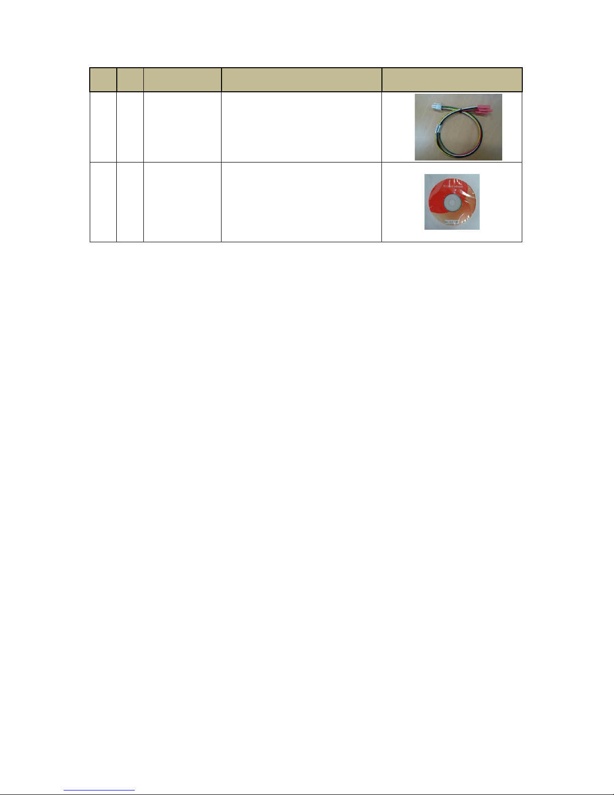
12
1
Car Signal Cable
13
1
PC Viewer Installation CD (or SD card)
& User Guide

11
2. Specifications
Category
Model
Remarks
SVC400GPS-L
SVC800GPS-L
Video Inputs (max)
4
8
NTSC/PAL
selectable
Video Out
1
NTSC/PAL
selectable
Audio Inputs (max)
4
8
Audio Out
1
Video Format
H.264
Audio Format
G.711
Recording Resolution
NTSC: 704 x 480, 704 x 240, 352 x 240
PAL: 704 x 576, 704 x 288, 352 x 288
Recording FPS
NTSC: 60(D1) / 120(Half-D1) / 240(CIF)
PAL: 50(D1) / 100(Half-D1) / 200(CIF)
Alarm In
4(O/C) + 3(Voltage) + 1(RPM)
Alarm Out
2
LED indicators
Power, Rec, Alarm, LAN
Removable Storage
SATA I interface, 2.5”, HDD or SSD
External Device
USB Host 1 (Rear), SD Card 1 (Front)
LAN
Wire: 10/100 bps
G-Sensor
Internal 3 Axis
Serial Port
2+1(GPS) * RS-232C
Signal Port
5: Left, Right, Brake, Reverse, Speed
Input Interface
Front Button:
up,down,left,right,enter,esc,ch,search,fn,s
tatus
Power Out
DC 12V : 1 (Front) + 1 (Rear)
Application Language
English, Japanese, Russian, Korean
Chinese Simplified/Traditional, Portuguese
SW
PC Viewer
Allowable Temperature
Range
-10 ℃~ 60 ℃
Allowable Humidity
Range
0 ~ 90 %
Max Shock Tolerance
3G (SSD), 1G (HDD)
Power/Consumption
DC 24V/1A
Weight (approx.)
1.08 kg = 970g (main unit) + 110g
(removable Pack)
Dimensions
1 DIN: 178mm(W) x 50mm(H) x
180mm(D)

12
Interfaces
IO – Front
Removable
HDD/SSD Slot
2.5”, SATA I, Key Lock type
Key Lock (Power on)
Key Unlock (Power off)
1ea
SD
FW Upgrade
Configuration File Loading
EMS, Auto back up
1ea
Video Out
RCA type, Main video out
1ea
Audio Out
RCA type, Playback audio
1ea
External Power Out
DC 12V
1ea
LED
Power, Rec, Alarm, LAN
4ea
BEEP
Status, Error
Button
Up,Down,Left,Right, Enter
Channel,Search,Function,Esc,Status
10ea
IR Receiver
IR Remote Controller(reserve)
1ea
IO – Rear
Video Inputs
Video (NTSC/PAL) In
Camera Power (DC 12V)
8ea
Audio Input
Line in
8ea
Car Signal
Left, Right, Brake, Reverse, Speed
Pulse
5ea
Alarm In
1~4 : Voltage off/on
5~7: Normal open/close
8: RPM
8ea
Alarm Out
Digital output
2ea
Serial Port 1
Debug
1ea
Serial Port 2
Tachometer
1ea
Serial Port 3
External GPS
1ea
USB
Host A type
FW Upgrade
Configuration File Loading
1ea
LAN
10/100 Mbps, RJ-45 jack
1ea
Power In
DC 12V / 24V
1ea
External Power Out
DC 12V
1ea
13
3. SVC400GPS-L Overview
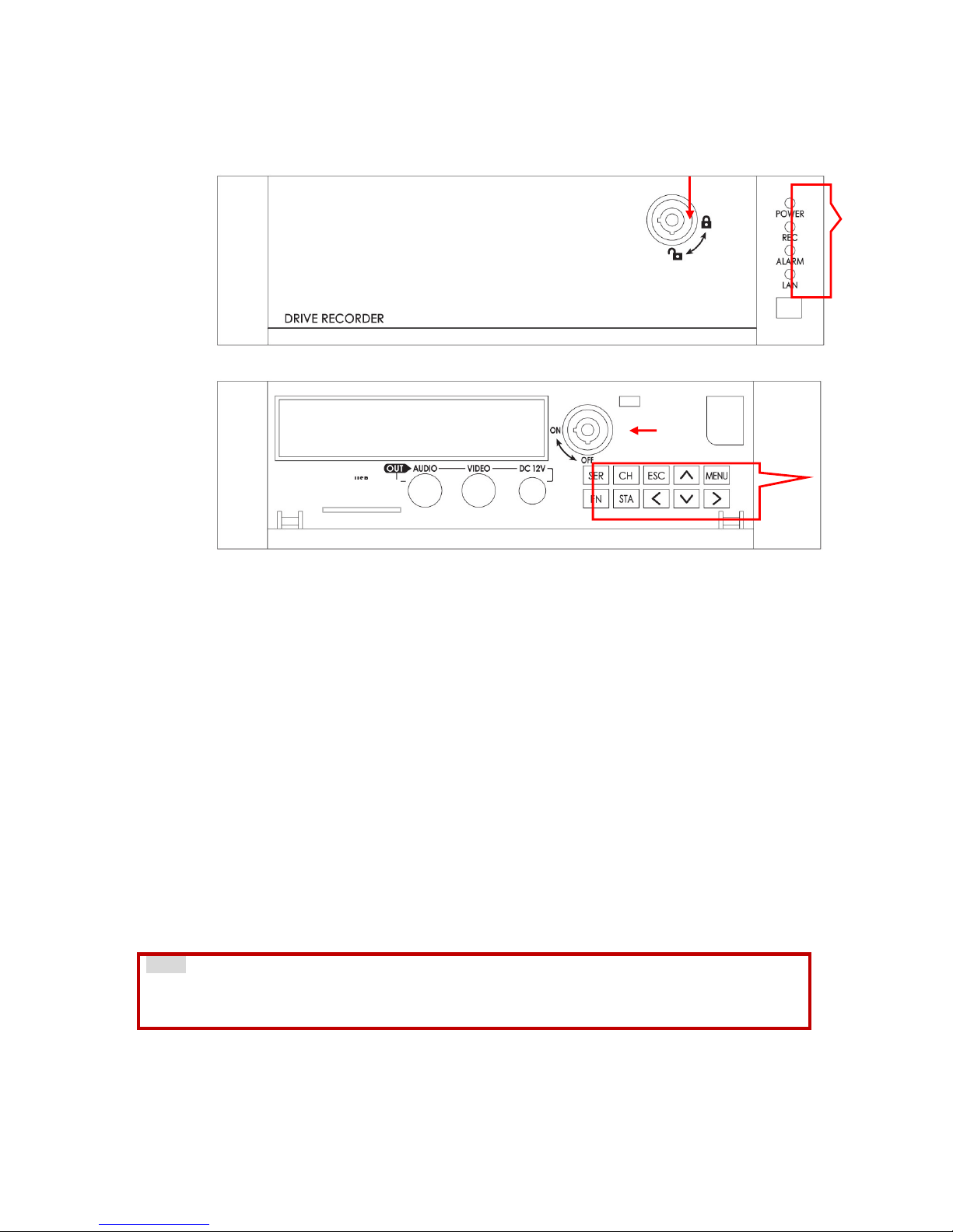
3-1. Front
①Cover Lock
②LED Indicator Lights
[POWER]: Illuminated when the unit is powered (Green LED)
[REC]: Illuminated when recording (Orange LED)
[ALARM]: Illuminated in any fail conditions (Red LED)
[LAN]: Illuminated when connected to the network (Orange LED)
At power on, the POWER LED will illuminate immediately and the unit will go into
system check. Once device is operational, the REC LED will also illuminate. This
usually takes about a minute but in some cases, the device may need to reboot
in which case it will take about 5 minutes
③Control Buttons
[SER]: Search data by date using calendar index
[CH]: Select single camera view
[MENU]: Set up
[ESC]: Return to previous screen
[<∧∨>]: Direction keys to move selections during set up
[<]: Change layout of live screening to 9 split screen
[>]: Change layout of live screening to 4 split screen
[∨]: Press down for 3 seconds to stop EMS data recording and safely eject
SD card
Note
While accessing the menu, data may be being recorded on the SD card, please use the
[ESC] key to exit the Set Up mode before ejecting SD Card
[FN]: Function key
[FN] + [∧]: Upload device settings
* Uploading Device set up: Store your device settings onto a SD Card or USB
memory stick using the PC Viewer, plug in the memory media into the device
while in operation, pressing the [FN] + [∧] together will upload and change the
settings.
①
②
③
⑨
⑤
⑦
⑧
④
SD ▼
⑥

14
[FN] + [∨]: Download device settings and log data
* Downloading Device set up: Plug in a SD Card or USB memory and press the
[FN] + [∨] together to download the settings
Note
1. When the device is in Set Up mode, both uploading and downloading the
settings is not possible.
2. When both SD card and USB memory stick are plugged in, even if there
are no recorded settings, only the SD card will be read
[STA]: Selects overview information and display type on monitor
④Removable HDD(SSD) Cartridge: When the Key lock is on ON, the removable
cartridge cannot be inserted or pulled out
Note
Remove the Removable HDD (or SSD) Cartridge only after Key is unlocked,
and LED lights are out.
⑤Key Lock: Locks Removable Cartridge and also turns the power on and off
A. When using the Key Lock to power up and off
"Off →On: Immediately powers up, operational in 40 sec
"On →Off: Initiates shut down and will fully power off in 15 sec
B. When using the ACC Signal to power up and off
"Off →On: Powers up in 5 sec, operational in 45 sec (the [REC] LED will
illuminate)
"On →Off: Stops recording immediately, initiates shut down in one
minute, and will fully power off in 1 min and 15 sec
* The delay time for record off and power off time can be modified using the
power board’s dipswitch inside the device. For more information, please
consult with your dealer.
⑥SD Card Slot: Plug in SD card to upload and download EMS data
* SD cards can be inserted at any time but must be safely ejected by
pressing [∨] for 3 seconds prior to removal.After you hear the double
beep, push in the SD card to unlock and then eject. SD cards can also be
safely removed after power shutdown of the SVC unit.
A. Downloading the setting and log files
#Insert the SD card, Press the [Fn] and [∨] key simultaneously to
download the setting and log files.
#Two short beeps will sound when download is finished. One short
beep will sound if there is an error.
#Please follow the SD card safe ejection instructions described above
when removing.
#The downloaded data will be stored in the SD card in the folder
“dvr_config_down”, and in the sub-folder “MAC_Mac Address“ as
files: “dvrid.ini, setting.ini, version.ini, system.log”
B. Uploading the setting files
#Set and store device setting files using the PC Viewer (For
instructions refer to section 10-2)
#Insert the SD card until it locks and press [Fn] and [∧]
simultaneously.
#During the upload, the device will sound three short beeps
continuously

15
#Two short beeps will sound when upload is finished. One short beep
will sound if there is an error.
⑦Video Out Port
⑧Audio Out Port
⑨DC 12V Power Out
16
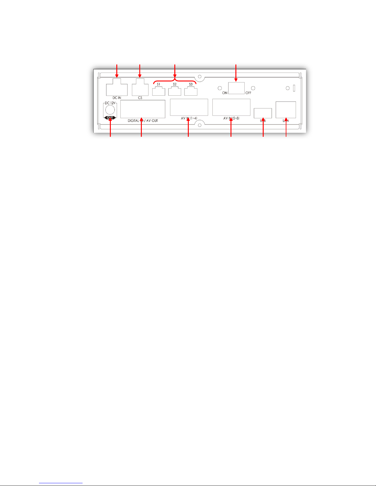
3-2. Rear
①Power Connector
Use the included power cable bundle for this connection, the battery cable
connects to the battery power and the ACC cable connects to the ignition or
main power switch.
②Car Signal Connector
Use the car signal cable bundle for this connection. Connect the appropriate
car signals to the labeled cables.
③Serial Ports
Port 1: Connect external device usually used for system maintenance
Port 2: Connect external device usually used to connect EMS Alert Unit
Port 3: Connect external device usually allotted for external GPS
④Main Power Switch
⑤Power out (DC 12V)
⑥Digital IO / AV out Connector
Digital Input 1: Allotted for RPM signal
Digital Input 2 ~ 8: Connects to other signal inputs such as panic switch,
horn, door open and close, etc.
Digital Output 1 ~ 2
Audio / Video Out
⑦AV In (1~4) Connector
Cameras 1 ~ 4: Video, audio, and 12 V power supply
⑧AV In (5~8) Connector
Cameras 5 ~ 8: Video, audio, and 12 V power supply
⑨USB connector
Supports firmware up-grade, set up file upload / download, and network
connection
⑩Ethernet connector
Supports network connection
⑤
⑥
⑦
⑧
⑨
⑩
ㅇ
①
②
③
④
17
Main Unit Set Up
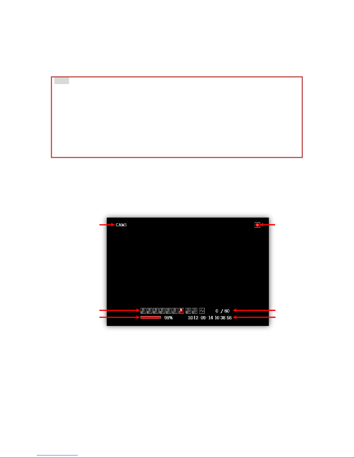
1. Live Screen
1) The device will become operational in one to two minutes after the power on.
2) When the device is fully operational, the [POWER] and [REC] LED lights will
illuminate.
3) While operating and if a monitor is connected, the below image will show as
the default display setting.
*the default viewer setting is CAM1 as below. This can be changed by pushing
[CH] for other camera views, [<] to show all camera views, [>] to show four
camera views at a time.
①Camera name: Default is CAM 1 ~ CAM 8 but can be renamed
②Digital input 1~7, alarm output 1~2, G-sensor indicators, refer to the
“Live Display Indicators” Insert below
③SSD or HDD record status bar
④Date and time
⑤Speed indicator: Current speed / Speed limit
⑥Recording indicators, refer to the Live Display Indicators Insert below
Note
1. When the device is properly set up and powered on, power on and off can be
controlled by either the main power switch or the ignition, depending on your
own connection arrangement.
2. At power on, the unit will automatically self-check. If required, it may re-boot in
which case it will take up to 5 minutes for the device to be operational.
3. The delay power-on settings can be modified with the dipswitches, please consult
with your dealer.
4. If the SSD or HDD is not inserted into the unit, the [REC] LED will not illuminate.
5. If the [ALARM] LED is illuminated, there may be a problem with the camera
connection or data storage device, please contact your installer.
⑤
⑥
①
②
③
④

18
Live Display Indicators
Video Loss, No Camera
Detect Alarm in 4
Motion Detection
Detect Alarm in 5
Audio Record
Detect Alarm in 6
Continuous Record (RED)
Detect Alarm in 7
Event Record (YELLOW)
Detect Alarm in 8
Detect Alarm in 1
Activate Alarm out 1
Detect Alarm in 2
Activate Alarm out 2
Detect Alarm in 3
Detect G-sensor variability
2. Information Screen
1) Press [STA] four times to switch to the Information Screen.
①System Version: Displays firmware version
②Micom (chipset) Version
③Video Standard: Displays video Standard, either NTSC or PAL
④Mac Address
⑤GPS: Displays longitude, latitude, and speed
* If there is no GPS value, check your location to see if there is any GPS
signal reception.
⑥Alarm In/Out: Displays digital input 1 ~ 7 and digital output 1 ~ 2. 0
means no signal, 1 means there is a signal
⑦Speed Pulse: Displays speed pulse and speed measured by the vehicle’s
speed pulse
* If the speed indicated here varies with the vehicle’s speedometer, please
re-configure the car pulse type by going to [Menu -> Device -> Signal ->
Carpulse Type] and selecting the correct type.
⑧Car Signal: Displays car signals
i. Left turn signal: Left
ii. Right turn signal: Right
iii. Brake pedal: Brake
SVC400GPS(L
19
iv. Reverse gear: Reverse
v. Emergency: Left & Right
* Multiple signal display is possible
⑨G-Sensor
* When installing your device, configuring your G-sensor is essential. Refer
to Appendix B for the configuration values and select the correct angle setup
for each axis.
⑩RPM: Displays engine RPM measured by RPM pulse.
* If the RPM indicated here varies with the RPM gauge, please re-configure
the RPM pulse type by going to [Menu -> Device -> Signal -> RPM Pulse
Type] and selecting the correct type.
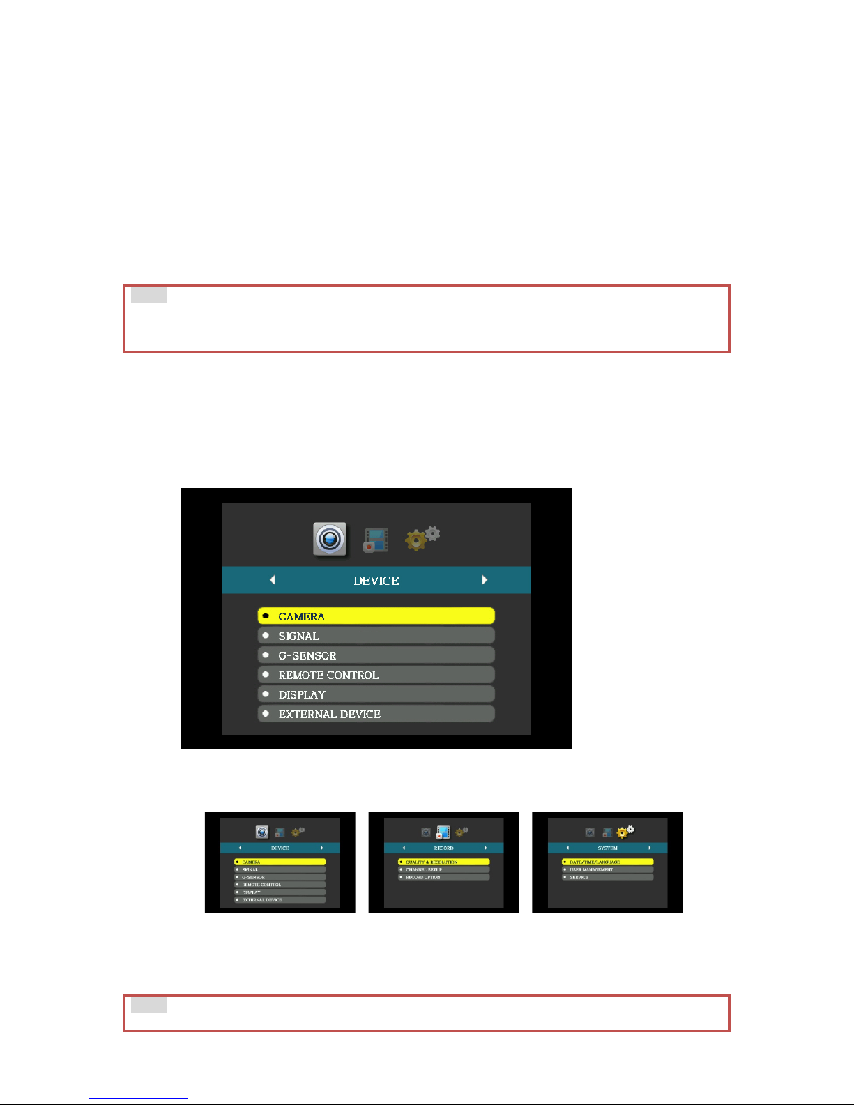
3. MAIN MENU
1) To access Menu, press [MENU] and the default password: [>][<][∨][∧].
The password can be changed, refer to the below Notice box.
2) After typing the password, press [MENU] again and the below screen will
show.
3) Within Menu, there are three directories: Device, Record, and System.
4) Use [>] and [<] to change directories.
5) Within each directory, there are sub-directories that can be accessed by
pressing [∨][∧] and then [MENU]
6) Press [ESC] to return to previous stage.
Note
The values on the Information Screen refreshes every second, please give ample time
for the device to display before changing the values or settings.
Note
The password can be changed by going to [MENU -> SYSTEM -> USER MANAGEMENT ->

20
PASSWORD]. Press [MENU] to change the password. Use a combination of [>], [<],
[∨], [∧] as a password then press [MENU] to set. If left empty, no password will be set.
Repeat this process to confirm. Press [ESC] to return to previous stage and exit MENU.
Note
1.Not all configurations can be set from the main device, please use the PC Viewer if
you wish to access the full array of configurations.
2.The categories that cannot be changed are shaded in grey.
This manual suits for next models
1
Table of contents
Other Smart Witness DVR manuals

Smart Witness
Smart Witness SVC400L User manual

Smart Witness
Smart Witness SVC400 User manual

Smart Witness
Smart Witness SVC400P User manual

Smart Witness
Smart Witness SVC420/820GPS User manual

Smart Witness
Smart Witness CRX-S User manual

Smart Witness
Smart Witness CP4S-NA User manual

Smart Witness
Smart Witness SVC400L User manual

Smart Witness
Smart Witness SVC400GPS User manual


