Smart Witness SVC400L User manual

1
SVC400L/SVC400P/SVC800P
Mobile Video Recorders
User Manual

2
SVC400P/SVC800P - User Manual
1 PRODUCT CHARACTERISTICS AND OVERVIEW
1.1 PRODUCT OVERVIEW
SVC Mobile DVRs are a cost-effective and functional mobile digital video recorder specially designed for vehicle
surveillance and remote monitoring, combined with high-speed processor and embedded operating system. The
advanced H.264 video compression and decompression, wireless transmission, GPS location makes these DVRs
to be a very powerful solution for vehicles.
VIDEO AND AUDIO DVR FERATURES AND CAPABILITIES
4/8 channels for video input, D1 at 12fps/15fps continuous or priority video recording and live view display.
Semi-transparent Graphical User Interface (GUI) allows the user to see the live display simultaneously
A special file system (NVRFSTM) improves the security level of data, providing self-recovery function,
self-check, self-backup for certain critical data and avoiding data fragment that affect system efficiency.
Flexible Mirror recording provide at least 2-3 hours back-up recording evidence (in case fail occur in HDD).
Watermark prevents any modification in the recorded file
Dual-Stream for wireless transmission.
Better Compression rate at H.264 (50% less than MPEG4) ensures a more efficient method of storing data
by taking up less hard disk space.
4/8 channels for high-fidelity, digitally recorded, synchronized audio matched to 4/8 video channels
User friendly criteria to playback the events associated video only.
Automatic timer to resume the live display if the unit is idle for user defined timings.
User-selectable settings for quality and audio record enable/disable for each video channel.
12v power supply for multiple devices such as cameras, sensors, relays and any other accessories.
Selectable frame rate with event-triggered burst recording speeds up to 30FPS/camera.
Multiple alarm inputs with selectable pre-alarm and post-alarm record timings.
REMOTE CONNECTION CAPABILITIES
Handheld Infra-Red controller with On Screen (OSD) for quick access to recorded video and settings menu.
PC-Based Client software for live viewing, playback video, playback events associated video, and download
capabilities
Support CMS (Central Management System) for remote monitoring by CDMA/GPRS/EDGE/3G and WIFI,
PAS (Playback Analysis Software) for video playback, meta-data analysis.
ACCESSORY MODULES FOR SVCSeries Mobile DVRs
Video Interface Module including GPS location and speed.
Vehicle Motion Manager includes 3-axis Inertia Sensor to determine video-matched motion events
Wireless module CDMA/GPRS/EDGE/3G, WIFI for transferring data to CMS server for remote monitoring.

3
SVC400P/SVC800P - User Manual
1.2 PRODUCT SOLUTION
Passenger statistic
LED
IR control
Control center
CMS client
Playback software
GPRS
CDMA
EDGE
3G
Wireless transmission
Station Announcement
Camera
Live view
4
SVC400P/SVC800P - User Manual
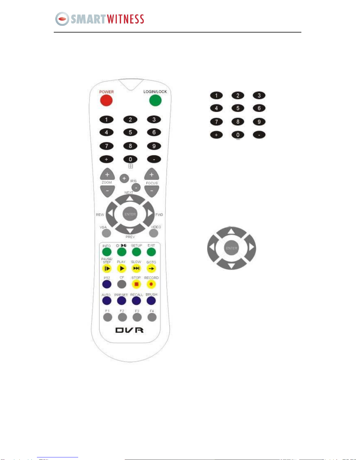
2 HANDHELD IR REMOTE CONTROL
Each Mobile DVR includes a handheld Infra-Red (IR) controller that allows the user to transmit
commands to recording module and display on screen control menu
HANDHELD IR CONTROL KEY FUNCTIONS:
Numeric
Input Keys
Use the numbers to input
values in the system setup
screen or switch through the channels in live
mode and playback. +and - buttons
are used to increase setup values one by one.
Navigation
Arrows
Use the ARROW keys to move between
selections, input fields and icons.
Press ENTER to select
and EXIT to return. Next and previous are
used to increase or decrease volume when at
live or search screens.

5
SVC400P/SVC800P - User Manual
1. NUMERIC KEYPAD:
[0-9] keys: During setup, number keys are used to input values.
For viewing channels 1, 2, 3 and 4 use 1, 2, 3 and 4 on numeric keypad respectively.
[+], [-] keys: During setup, plus and minus are used to select next or previous values.
During real time view of individual camera, after you pressed key use plus and
minus to make the color adjustments. Pressing will navigate through the color
adjustment options. Please be advised that the unit needs to stop recording before any color
adjustments are made.
2. SETUP MENU NAVIGATION:
▲, ▼: Up, down directional keys: Moves selection up and down in setup menu.
►, ◄: Left, Right directional keys: Moves cursor left or right in setup menu.
[ENTER] key: During setup, select and save entry
During Playback, display all the information that setup by OSD overlay
menu.
3. OTHER KEYS FUNCITONS:
LOGIN/ LOCK
If the security is enabled in the setup, use LOGIN / LOCK or SETUP
key to enter the user setup. It is important to remember the
password due to without restoration function.
POWER
The Power button can reset the DVR in to sleep mode (unit will stop
recording while in the sleep mode)
VGA
Switch the output mode to VGA (Include: VGA1, VGA2, VGA3)
VIDEO
Switch back from VGA to composite output (V1)
Swapping between multi-channel and single channel monitor
While in surveillance screen only. Press this button to change the
number of display channels. By pressing the key, display channel
change in the sequence of four→ one→ two→ three→ four→one
(recycle)
Brightness, contrast, color adjustment per channel. Use [+] [-] button
to change the values. User can adjust the values for each channel
individually.
SETUP
System setting screen (may require login)
EXIT
Returns to the previous menu. Pressing exit key takes one step back
in the until the live monitor screen is displayed
Stop
Used to stop the recording manually.
Record
Used to start the recording manually.
PAUSE/STEP
▐►
Freezes playback to a single frame and can advance one frame at a
time. To advance the frame press Pause / Step to move frame by

6
SVC400P/SVC800P - User Manual
Check battery in place of remote controller since no battery in the standard package
frame. Press EXIT to return to normal playback speed
PLAY ►
Starts/Resumes playback from any other mode (FF, RR, Frame by
Frame etc)
SLOW
Reduces playback speed to 1/2, 1/4, 1/8 modes. Press PLAY to
return to normal playback speed
GOTO
Quick search mode within the file playing back. Select the desired
file and start to play. Press GOTO button and input the desired time.
Select START to jump to the specific time
NEXT
Increase volume while playback (if audio is recorded) or multimedia
playback
PREV
Decrease volume while playback (if audio is recorded) or multimedia
playback
REW
Rewinds the video while playback. X2 and X 4 modes available
FWD
Fast forward the video while playback. X2 and X4 modes available
CF
No use at present
[F1], [F2],[F3],[F4]
Reserved for future use
4. PAN/TILT/ZOOM FUNCTIONS
While connect with PTZ camera and using the RS232C in DB25, following command can control with PTZ
camera with following function:
[ZOOM IN +], [ZOOM OUT -]
ZOOM IN/OUT
[IRIS +], [IRIS-]
IRIS control
[FOCUS +], [FOCUS -]
FOCUS IN/OUT
PTZ
Start to active the PTZ function
AUTO
Auto run with the PTZ pattern
PRESET
Preset default position
RECALL
Recall the set program
BRUSH
Brush the glass screen
7
SVC400P/SVC800P - User Manual
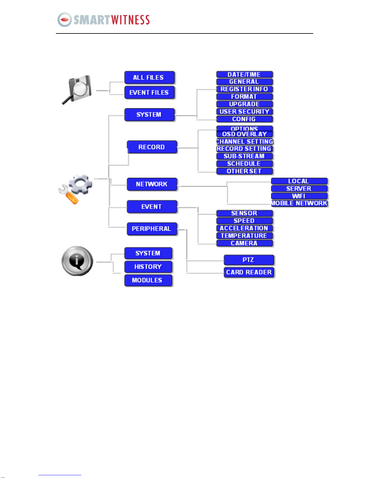
3 MENU TREE
Menu structure tree
8
SVC400P/SVC800P - User Manual
DVR GUI is semi-transparent; you can see the live view when you make GUI configurations
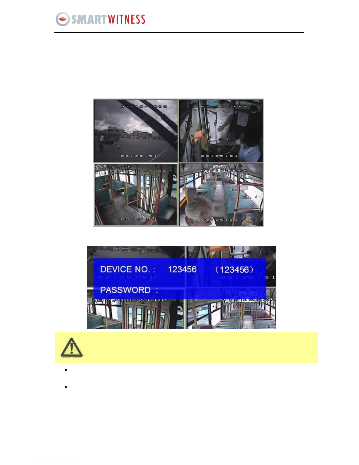
4 SYSTEM START UP
After connecting the DVR to a vehicle power supply turn on the vehicle ignition and the unit will
automatically start recording. Power is normally supplied to the DVR as long as the vehicle ignition is
ON. “Display only view” of the cameras is immediately available to be viewed in quad view.
SYSTEM LOGIN FOR SETUP
When Password is set to disable, press SETUP key on the handheld controller into the setup menu
directly;
When Password is set enable, press LOGIN/LOCK OR ENTER key on the handheld controller, the setup
menu will appear:

9
SVC400P/SVC800P - User Manual
User default password is 22222222, and Admin password is 88888888.
OPERATOR PASSWORD CORRECT indicates permission is limited to video, sensor menu.
ADMIN PASSWORD CORRECT indicates full access to DVR.
SUPER PASSWORD CORRECT indicates full access to DVR under the circumstance of losing the
password and modifies the MAC address.
Please press SAVE to confirm any change in settings and it will give you a notification if
successful. When you modify the settings for the network, it will restart automatically after you
exit to the live view.
The DVR will stop recording when enter into the configuration GUI.
You can input the letters and characters by software keyboard.
DEVICE NO.: The identification number of DVR (you can set the ID in the GUI)
PASSWORD: Enter the admin password or user password.
Keyboard: Press Enter to use keyboard to type device ID and password.
1 0~9, number key, press Enter to select the number.
2123: Input type shift key. (Number, capital, small letter)
3←delete, Exit.
5 MENU CONFIGURATION
This part will show all the main functions for DVR including research, setup and information:
Search is for searching all the video files and alarm files.
Setup for all the configurations for DVR
Information display for the DVR and the accessories working status.

10
SVC400P/SVC800P - User Manual
5.1 SEARCH
5.1.1 ALL FILES
You can search all the video files including normal files, alarm files by recorded time and file type. Please
highlight the option ALL FILES and then enter into following screen.
FILE TYPE: The type of the file including alarm file and normal file.
DATE: DVR system will display the current day automatically. The day with record files will be indicated
by green. If the day with ALARM FILES, it will indicated by yellow.
TIME: The default setting is 00:00:00; this time is for the start time for recording. For example: If the date
is 2009_04_14 and the time is 00:00:00, it indicates that you want to search the entire video file from
11
SVC400P/SVC800P - User Manual
Please active the lock files in EVENT menu. Only EVENT file can be locked since most of the
event files are very important.
If the video file is locked, then the file can not be deleted by HDD overwrite function. Only when
you unlock the files and the lock save time invalid, then HDD overwrite function will delete the
files. Only the HDD format will delete the locked files.
00:00:00 to 23:59 on 14th, Apr, 2009. If the date is 2009_05_16 and the time is 12:56:00, then it indicates
you want to search all the files from 12:25:00 to 23:59:00 on 16th, May, 2009.
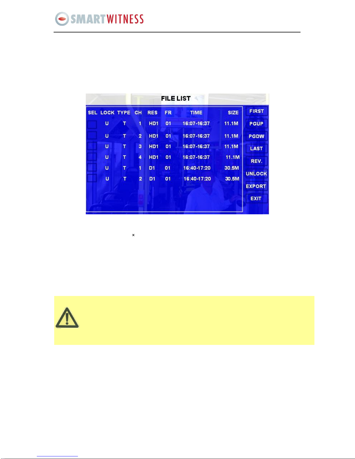
Please press SEARCH to enter into the next menu for listing out all the certain video files depends on the
setting or the file type, date and time.
SEL:For selecting the files for backup. Please press arrow key on remote control to select the file that
need to back up and then will display.
REV.: Press for selecting all or not. For example, if you do not select any file for backup, then press REV.
all the files are selected. If you select one file and then press REV. all other files are selected. (But the
selected one before not selected)
Lock: Lmeans this file is locked. UMeans this file is unlock.
EXPORT: Export the selected file to external device by USB port on the front of DVR.
Please connect the external USB storage device to the DVR and then press the EXPORT for backup. Then the
following screen will pop up.

12
SVC400P/SVC800P - User Manual
If you do not connect external storage device or the storage device is defective, then the system
will display NO THUMB DRIVE.
TOTAL: total quantity for the files that you selected for back up
No.: The file number that is currently being backed now
After successful backup, then the following screen will pop up.
If the DVR current video type is different with the setting that the DVR last recorded then the video file will not
playback. For example, the video type of recorded files is in NSTC, but now the video type is changed to PAL then
you won’t be able to playback the video file until you change the video type to NSTC.
The user will get the following screen if they the video type does not match:

13
SVC400P/SVC800P - User Manual
Please enter into the OPTION GUI and change the video type to be PAL manually and then the video file can be
viewed in playback
5.1.2 EVENT FILES
Search for all the event files LOG, not video file.
FILE TYPE: The type of the alarm file including I&O ALARM/ACCELERATION/SPPED/TEMP
ALARM/VL ALARM
DATE: The system will display the current date automatically. Any date with alarm recorded files
available to use will be indicated by yellow.
Please press SEARCH to enter into the next menu and will display the results as follows:
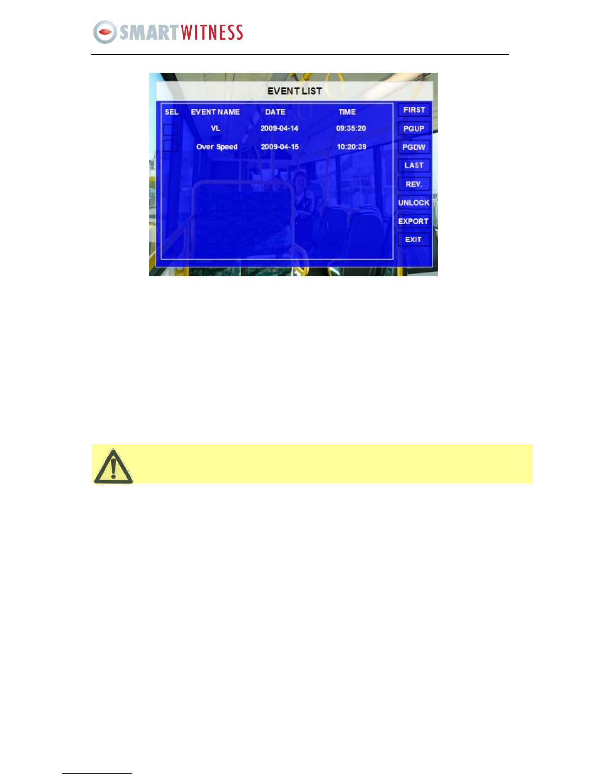
14
SVC400P/SVC800P - User Manual
This function only lists a LOG file for event name, start time, not video file. If you want to see the
actual alarm video, please search them in the ALL FILES menu.
SEL: For selecting the LOG for backup. Please use arrow key on remote control to select the LOG files
that need to be backed up and then √will display. Please press REV. to select all the files for backup or
not.
EVENT NAME: The type of alarm event (such as alarm for video loss, alarm for over speed, low speed
or high temperature, sensors etc)
DATE: Display the date when the alarm occurred
TIME: The start time when the alarm occurred
REV.: Press for selecting all or not (for example, if you do not select any files for backup, then press REV
to select all the files)
EXPORT: Export the selected LOG to external device by USB port on the front of DVR

15
SVC400P/SVC800P - User Manual
5.2 SETUP
Use ARROWS on the remote control to select SYSTEM and then press ENTER. The screen will show the menu
as below:
5.2.1 SYSTEM
16
SVC400P/SVC800P - User Manual
While setting the DST, the former date must be older then the new date. If the two
dates are the same, the DST will be invalid.
A) DATE/TIME
DATE FORMAT(US or Int’s): Press ENTER to select different format (MM/DD/YYYY, DD/MM/YYYY,
YYYY-MM-DD)
TIME FORMAT: 12H or 24H, Press ENTER to select different format.
TIME SYNC SOURCE: The system allow have the time synchronizing via by either “GPS” or “NTP”.
oWhile selecting the “GPS”, the device must have GPS connection and its GPS signal must be in
an area with good reception. To set the sync time in this menu, (the unit will record the time
difference-GMT offset), the unit will synchronize with GPS time once.
oWhile selecting the “NTP” (Network Time Protocol), the device must have network access
connection and assign the NTP IP location. This process run at 6:30am local time while the
system have network connection.
TIME ZONE: Please choose the correct time zone where the vehicle is located.
SYNC TIME: This is the time when the unit will sync the system time every day. The method depends on
the setting on the TIME SYNC SOURCE option:
NTP SERVER IP: Input the IP server does support NTP protocol, in order to allow the system can have
time synchronization through the network. [Example: "192.43.244.18", "129.6.15.28", "211.22.55.116",
"194.88.2.60"]
DST: Daylight Saving Time. Only when it set on, the following option will available:
oDST MODE: There are two modes: Auto / Custom. Auto: Set according to the international DST,
(i.e.: valid only between 2AM on Second Sun in March and 2AM on First Sun in NOV)
Scroll to SAVE to confirm the changes

17
SVC400P/SVC800P - User Manual
B) GENERAL
ON/OFF TYPE: ignition or timer.
A) IGNITION: for shut down delay function. For example: If you make the shut down delay time is 5 min,
then DVR will shut down after 5 min after the ignition off.
B) TIMER: It will start up automatically at the time your setup. If you select TIMER, then the following
screen will pop up.
BOOT UP TIME: The exact time for DVR starts to work every day.
SHUT DOWN TIME: The exact time for DVR shut down every day.
BOOT UP IN RECORDING TIME: ON refers to the record function being linked to the timer start-up (i.e.
if the setting for BOOT UP TIME is 06:00:00, the DVR will start to record even ignition is OFF).
18
SVC400P/SVC800P - User Manual
For TIMER type, if the setting for boot up time is 6:00:00 and shut down time is 11:00:00. After the
DVR is OFF, reboot up the DVR and DVR will check the system for 5 min and then shut down
again, you must enter into this menu to change the TYPE to be ignition. Anyway, if the time for
reboot up the DVR is not during 6:00:00 to 11:00:00, then DVR will shutdown in 5 min.
BUZZER SWITCH: ON means the buzzer will alarm when alarm happens
IDLE TIME (SEC): The time for the operation interface remaining idle before switching to the live
view.
EVENT FILES AUTO-EXPORT (USB): Reserve Use
Scroll to SAVE to confirm the changes
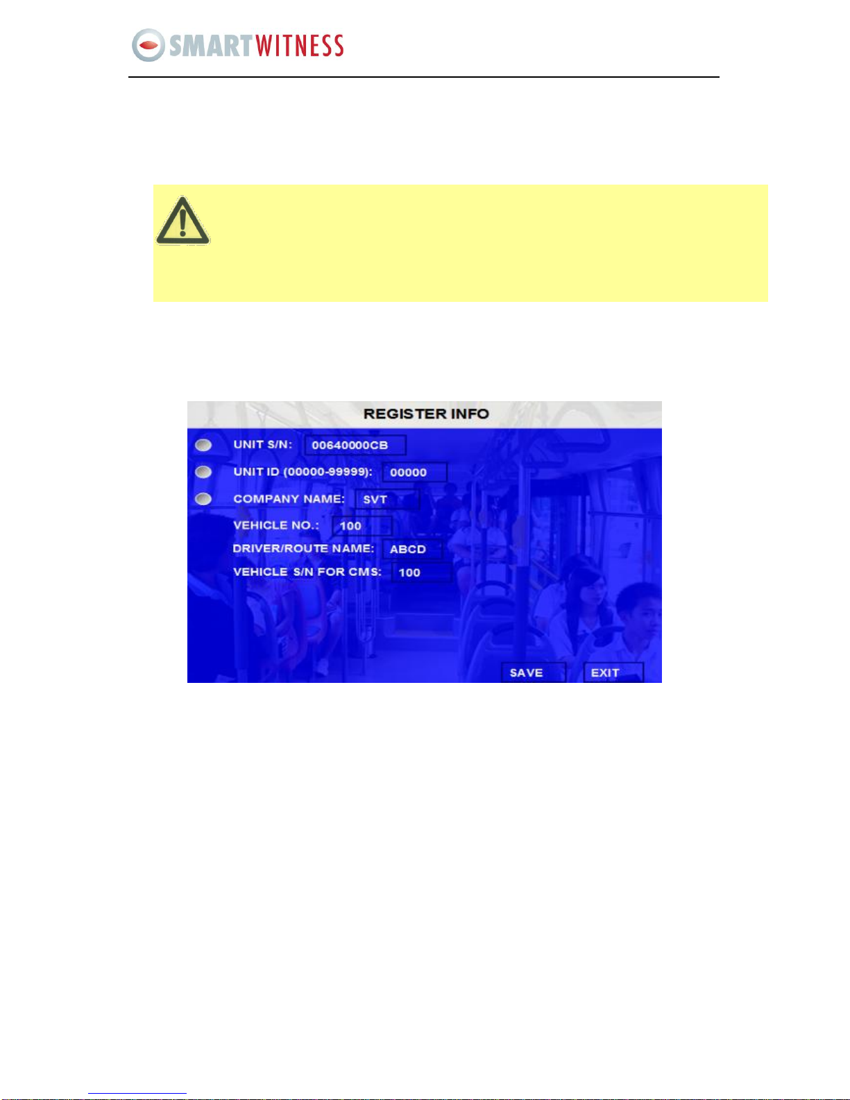
C) REGISTER INFO
UNIT S/N: The series Number for DVR. One DVR has only one S/N. This number is taken from a special
encrypted chip.
UNIT ID: Device ID. Use the NUMERIC keypad to enter the system ID from 00000 to 99999. This ID is
used when logging in to the unit (if security is enabled, set as yes).
COMPANY NAME: The name of company: Press the arrow key on the remote control and highlight this
option and then input the name of the company.
VEHICLE NO.: The number of the vehicles.
DRIVER/ROUTE NAME: The driver’s name and the route name
VEHICLE S/N FOR CMS: This is very important for CMS. Only this number can be recognized by CMS
Please Note: when you connect DVR to CMS ensure sure Vehicle No. and Vehicle S/N are not left blank ,
otherwise the CMS will not be able to register the SVC400P.
Scroll to SAVE to confirm the changes

19
SVC400P/SVC800P - User Manual
D) FORMAT
Select the device you want to format, HDD, SD card or external USB storage device.
DEVICE: Please press ENTER to select the target device for format. There are 3 options: HDD, SD and
USB. Then press FORMAT to format the storage device.
After formatting successfully the unit will restart automatically.

20
SVC400P/SVC800P - User Manual
E) UPGRADE
Upgrade to new firmware or MCU.
FIRMWARE: Upgrade the firmware.
MCU: Upgrade the MCU.
HOW TO UPGRADE THE FIRMWARE:
1. Please create one folder named dvrupgrade in thumb drive and then copy the firmware upgrade
file into this folder.
2. Insert the thumb drive into the USB port on the front panel of DVR.
3. Please enter into this interface and press UPGRADE, DVR will upgrade the firmware
automatically.
4. During the firmware upgrade, then following screen will pop up.
5. After upgrade successfully the unit will restart automatically as follows:
Other manuals for SVC400L
1
This manual suits for next models
2
Table of contents
Other Smart Witness DVR manuals

Smart Witness
Smart Witness SVC400GPS User manual

Smart Witness
Smart Witness SVC420/820GPS User manual

Smart Witness
Smart Witness SVC400GPS-L User manual

Smart Witness
Smart Witness SVC400P User manual

Smart Witness
Smart Witness CP4S-NA User manual

Smart Witness
Smart Witness SVC400 User manual

Smart Witness
Smart Witness SVC400L User manual

Smart Witness
Smart Witness CRX-S User manual


