Smart Witness SVC400L User manual

SVC400L
4 Camera Live Tracking Vehicle DVR
Installation Manual
Version 1.0

2
SVC400L - Installation Instructions
1. MAIN FEATURES ..........................................................................................................................................................3
2. PRODUCT OVERVIEW..................................................................................................................................................3
2.1 Front View .........................................................................................................................................................3
2.2 Back View ..........................................................................................................................................................4
2.3 Dimensions ........................................................................................................................................................4
3. PACKAGE CONTENTS ...................................................................................................................................................5
4. MOUNTING AND ENVIRONMENTAL REQUIREMENTS ...............................................................................................5
4.1 Location .............................................................................................................................................................5
4.2 Power.................................................................................................................................................................5
4.3 Humidity ............................................................................................................................................................5
4.4 Temperature ......................................................................................................................................................5
4.5 Vibration ............................................................................................................................................................6
4.6 Accessories ........................................................................................................................................................6
4.7 Injury .................................................................................................................................................................6
4.8 Maintenance......................................................................................................................................................6
5. INSTALLATION TOOLS .................................................................................................................................................6
6. INSTALLATION INSTRUCTIONS ....................................................................................................................................6
7. HOW TO CONNECT INPUTS AND OUTPUTS................................................................................................................7
7.1 The A/V Cable Definition (Video Input/ AV output) ..........................................................................................7
7.2 Specifications for the SENSOR BOX (sensor inputs and outputs) ......................................................................8
7.3 Specifications for 485 and 232 serial ports........................................................................................................9
8. WORKING STATUS .......................................................................................................................................................8
9. SETUP ........................................................................................................................................................................10
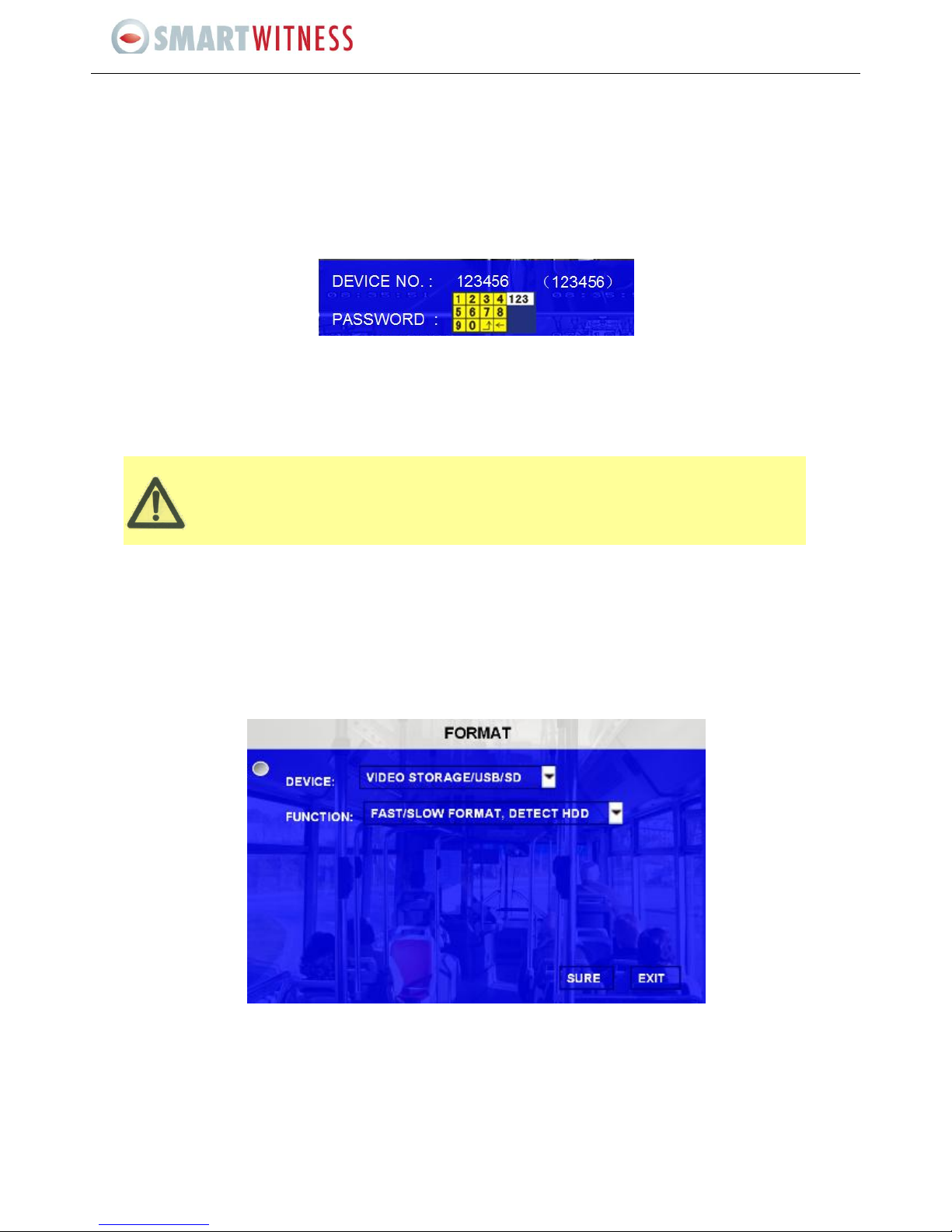
9.1 System Login....................................................................................................................................................10
9.2 SD Card Format................................................................................................................................................10
9.3 Record Setup ...................................................................................................................................................11
9.4 Playback and Backup .......................................................................................................................................12
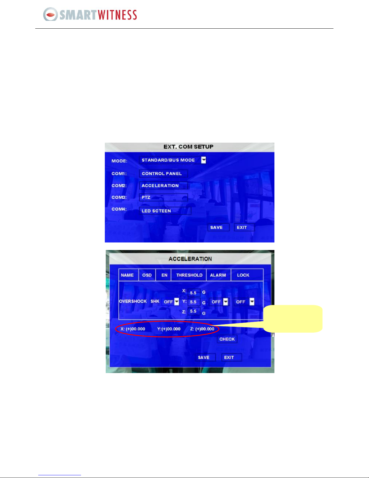
9.5 Serial Port Setup ..............................................................................................................................................13
10. SIM Card Installation and 3G Connection ............................................................................................................14

3
SVC400L - Installation Instructions
1. MAIN FEATURES
The SVC400L is an embedded mobile Digital Video Recorder that provides the perfect surveillance solution for vehicles. It
features H.264 video compression which guarantees a high quality image, high compression rate for smooth and fast network
transmission. The small profile design allows for easy and flexible installations options. The SD card storage allows a simple
recording process with access to view recordings easily. The powerful CMS software provides
Remote Monitoring
GPS Locations
Local Recording
Remote Downloading
Alarm Report System
Additionally the SVC400L’s CMS is set-up to provide automatic services for the protection of its data such as recovery, data-
monitoring and backup for all its critical data.
2. PRODUCT OVERVIEW
2.1 Front View
Items
Name
Description
Video Output
VIDEO_OUT
Video output
LED
(LED lights up or
flashes indicate the
same signal, it can be
setup based on
customer needs; the
table details the
message each LED
conveys when it is lit up
or flashing.)
SD-1
For recording
SD-2
For station announcement (in the wireless module)
GPS
For GPS signal
NET
For displaying the network status
POWER
The MDVR is power supplied
REC
Normal recording
ERR
Hardware Error or No HDD
ALARM
Signify an alarm.
VLOSS
Video Loss
IR receiver
IR
For receiving signals from the remote control
USB Interface
USB
USB2.0 for backing up the record files and/or upgrading the
firmware
Lock
LOCK
The SD card case needs to be locked before booting up MDVR;
otherwise, the boot-up will not be successful. MDVR will standby
whenever the SD card case is being unlocked.

4
SVC400L - Installation Instructions
2.2 Back View
Items
Name
Description
WI-FI ANT connector
WI-FI
For connecting WIFI ANT
GPS ANT connector
GPS
For connecting GPS ANT
2G/3G ANT connector
3G
For connecting the3G/GPRS ANT
Power input
DC8-48V
For connecting power input
Network port
RJ45
Network port ensures MDVR can go online
A/V Integrated input
A/V
A/V input and output
I/O Input and Output
I/O
I/O sensor input and output
EXTEND Interface
Fn EXTEND
For extend function, such as RS485 and RS232 serials port.
System Information
DEBUG
Testing serial port for MDVR.
MCU debug port
MCU
The port for MCU hardware debug
2.2 Dimensions
Front View
Rear View

5
SVC400L - Installation Instructions
3. PACKAGE CONTENTS
Please ensure that the SVC400L box includes the following items:
SVC400L
Video Input/ AV output cable
Power cable
Screws for installing the unit
A set of keys for locking and/or unlocking the HDD case
Handheld IR remote control (batteries not included)
Accessories available for the SVC400L include the following:
Alarm Input Box (SVA400A)
GPS Module and Antenna (SVA400G)
3G Module (SVA400T)
Wifi Module (SVA480W)
Din Plug to BNC Socket Adapter (SVA480C)
Locking Box (SVA400L)
4. MOUNTING AND ENVIRONMENTAL REQUIREMENTS
To ensure the SVA400L operates smoothly and within the product warranty compliance, please adhere to all following
installation instructions:
4.1 Location
Install the SVA400L in a dry and ventilated location ensuring that it is shielded from humidity, moisture, rain and/or
other sources of liquid. Do not install the SVA400L on a recessed surface where liquids may accumulate or on areas
where liquids may drip down onto the unit.
SVA400L should be installed on areas that are free of electromagnetic interference
Keep SVA400L away from direct sunlight and/or other sources of heat during installation.
Do not install the unit on a surface that is vulnerable to excessive vibration.
4.2 Power
SVA400L supports power supply ranges from 8v ~36v DC. Handle all electrical equipments with caution to avoid
injuries.
Turn off the power before connecting/disconnecting SVA400L from the power supply.
SVA400L is connected to both the vehicle ignition and the battery. The SVA400L’s power is supplied by the battery
when the vehicle starts up, and may drain the battery if the ignition is not turned off.
Correctly attach the SVA400L ground cable to the vehicle to complete the power circuit.
Disconnect SVA400L from the power supply when it is not in use for an extended period of time.
4.3 Humidity
The working humidity for SVA400L is between 20-95%.
Do not handle SVA400L with wet hands, while standing in water, or while in contact with other sources of liquid, as
these can potentially result in an electric shock.
4.4 Temperature
The SVA400L with SD card operates in a sealed enclosure with no airflow. Its minimum and maximum operating
temperatures are +5°C (41°F) and 55°C (131°F) respectively.

6
SVC400L - Installation Instructions
4.5 Vibration
Install a built-in vibration absorber for HDD.
4.6 Accessories
The SVA400L, cameras, wires and other accessories need to be placed at secure spots so that they won’t be misused
and/or destroyed by passengers and/or driver. Additionally do not install the unit/accessories that may restrict the
normal functions of the vehicle.
Do not attach any devices which are not specified by instructions and/or the manufacturers list of
authorised/compatible accessories.
4.7 Injury
The SVA400L, cameras, wires and other accessories need to be properly installed to prevent damage; and all
transportation regulations should be followed to avoid passenger injury.
4.8 Maintenance
To clean surface(s) of the SVA400L, only use cleansers that are approved for electrical equipments. Do not use
unspecified chemicals or household cleansers.
5. INSTALLATION TOOLS
Please ensure that you have the following tools available prior to commencing an installation:
Drill and bids
Screws
Wire cutters and wire connectors
Test for voltage and electric current
6. INSTALLATION INSTRUCTIONS
Follow these guidelines when installing SVC400L:
Unpack all components provided in the package.
Disconnect any source of power supply and/or devices.
Locate a proper spot to install the SVA400L and install a built-in vibration absorber if required.
Locate a reliable electrical ground point in the vehicle.
All wires and connections should be gathered to the back of SVA400L.
Connect to a power source and turn on the vehicle ignition to test the unit.
Meet all legal requirements for installing and/or operating a video surveillance, such as labelling all the essential
information on the SVA400L. Video surveillance statues vary across nations; please abide to the local statues.

7
SVC400L - Installation Instructions
7. HOW TO CONNECT INPUTS AND OUTPUTS
7.1 The A/V Cable Definition (Video Input/ AV output)
Specifications for the PINs:
A/V Cable interface definition:
Item
Name
Explanation
A/V INPUT
VIN1~VIN4
A/V input is a 4-pin female connector; 4CH machine has 4 A/V inputs, 8CH
machine has 8 A/V inputs. Feet 1 is for 12V power input, feet 2 is for GND,
feet 3 is for audio input, and feet 4 is for video input.
A/V OUTPUT
AV OUT
A/V output is a 4-pin male connector; feet 1 is for 12V power input, feet 2
is for GND, feet 3 is for audio input, and feet 4 is for video input.

8
SVC400L - Installation Instructions
7.2 Specifications for the SENSOR BOX (sensor inputs and outputs)
SENSORs 1-6 are the inputs for I/O sensors,
SENSOR OUT is for sensor output connection
SPEED- and SPEND+ are for speed sensor, which connect to the speed pulse of the vehicle.
Firstly, follow the steps of GUI > SETUP > EVENT > SENSOR; then, enable the sensor switch; and make sure the alarm switch is
ON, as shown below:
The SVA400L has 6 Alarm inputs and 2 Alarm outputs. All alarm inputs are I/O PWL which can reflect various vehicle statuses
such as braking, turning left etc. A schematic diagram of the alarm input ‘braking’ is shown below; when the brake is applied the
SVA400L will detect the I/O PWL, the alarm LED will light up (or flash) and will record this event.
Stoplight
+24V
Braking vane
Connect to SVC400L sensor input

9
SVC400L - Installation Instructions
All alarm outputs are PWL outputs, drive ability is 200MA, and the voltage is +12V, if you need more than that, please connect to
an external relay. An alarm output photoelectric wiring diagram is as follows:
7.3 Specifications for 485 and 232 serial ports
There are two 485 serial ports and two 232 serial ports, the functions are the same.
These serial ports can connect to accessories purchased from Shenzhen Streaming Video Technology, such as the inertia sensor
(acceleration), control panel, PTZ, station announcement, and the card reader etc.
Please Note: 485A means 485+, 485B means 485-
8. WORKING STATUS
Check all the LEDs when the device starts up:
POWER is ON means the power is normal
ERR is ON means there is no SD card or there are some other hardware errors
NET is ON means the net module is normal
VIDEO LOSS is ON indicates video loss
The SVA400L may be malfunctioning if there is no live view when all the LEDs are ON. Please contact technical support
for additional support.
24V
Alarm output

10
SVC400L - Installation Instructions
Please Note: If only the POWER LED is on and there is no live view output after SVA400L has started up, then please check
if the SD card has been locked properly.
9. SETUP
9.1 System Login
System Login for Setup:
DEVICE NO.: The unit ID of MDVR, which is the number in the right bracket.
PASSWORD: Enter the admin password or user password.
Please move the cursor to “123” to change the input mode, such as numeric key, capital letter, small letter and/or
characters.
9.2 SD Card Format
After you have installed a new SD card enter Graphical User Interface (GUI) to format the SD: SETUP > SYSTEM > FORMAT, and
then select the device you would like to format: SD card and/or external storage device.
It is extremely essential and important to format SD, as the formatting ensures that HDD would have the required file system
format. Normally, select FAST FORMAT to format HDD. The unit will restart automatically after successful formatting.
FAST FORMAT is the same as quick format on PC.
SLOW FORMAT means checking the existence of bad sectors in HDD, the system will remember if there are bad ones
and will not write data in this place again.
DETECT HDD means it will make sure not to lose data when the HDD has physical damage(s).
Please Note: For HDD installation, follow the guidelines attached in the accessory box.
User default password is 22222222, andAdmin password is 88888888.
OPERATOR PASSWORD CORRECT indicates permission is limited to video and sensor menu.
ADMIN PASSWORD CORRECT indicates full access to SVA400L.
SUPER PASSWORD CORRECT indicates full access to SVA400L under the circumstances of lost
password and/or the MAC address has been modified.

11
SVC400L - Installation Instructions
9.3 Record Setup
Setup the related parameters for Recording:
Go to SETUP > RECORD > OPTIONS to setup the basic parameters such as video type, record mode etc., as detailed below:
Go to SETUP > RECORD > CHANNEL SETTINGS to setup resolution, frame rate, normal recording quality and recording quality
when there is an alarm, for each channel:
RES: Resolution standard is optional; it can be D1, HD1 and/or CIF. D1, HD1 and CIF refers to DVD standard, super VCD
standard and VCD standard respectively.
FR: Frame rate = frames per second, the unit is fps. The frame rate for 4CH D1, 4CH HD1 and 4CH CIF is 48fps, 60fps and
100fps respectively.
QUALITY: Image quality, is measured in 4 levels with Level 1 being the best.
Please Note: The recording file size of a channel in CIF for an hour is approx 330MB. Given everything else being equal,
using HD1 recording will double the recorded file size.

12
SVC400L - Installation Instructions
9.4 Playback and Backup
Go to ALL FILES > search for the record files, and then use directional keys on the IR remote control to select the file you
would like to playback and then press Enter to start the playback. The user can playback one channel at a time. You can
move the cursor to SEL, select the recorded files you would like to backup, and then press EXPORT to backup the files. The
following screen will pop up:
Please Note: the recorded file that is being exported to an external USB storage drive is in a H.264 format, and can be
viewed using the playback software. Playback can also be carried out by connecting the removable HDD and PC using a USB
cable.

13
SVC400L - Installation Instructions
9.5 Serial Port Setup
SETUP > PERIPHERAL > EXT.COM SETUP
There are two options to choose ; STANDARD and BUS MODE:
STANDARD mode you can select an external port for each COM
BUS mode COM1 and COM2 are for station announcement and the amplifier board respectively, and these two
are unchangeable; whereas COM3 and COM4 are changeable.
If COM1 is selected as the control panel, then you should connect the control panel to serial port 1 for it to run properly.
Please Note: COM1 means 232TXD1, COM2 means 485-2, COM3 means 485-3, and COM4 means 485-4. PTZ is
recommended to connect to either COM3 or COM4.
Take inertia sensor for example: if an inertia sensor is connected to SVA400L then you can find the values for the sensor in
GUI (SYSTEM > SENSOR > ACCELERATION and then press CHECK):
After installing the inertia sensor, make sure that the ENABLE switch is turned on. Then press CHECK to verify its current
values (all the values will be defaulted to 0).
If you move the
inertia sensor, then
the values for X/Y/Z
will change.

14
SVC400L - Installation Instructions
10. SIM CARD INSTALLATION AND 3G CONNECTION
Remove the 3G/GPS module from MDVR (see below)
Unscrew the 3G/GPS module and open the cover (see below)
Please Note: the SD card here is other purposes and does not need to be used. SD card for recording should be inserted at
the front panel of SVA400L.
Carefully insert the SIM card in place, put on the SIM card cover and screw all parts together. Then, insert the
3G/GPS module into the SVC400P unit; and please make sure that it is properly connected to the 3G antenna.
Follow the steps of GUI > SETUP > NETWORK > MOBILE NETWORK; select the mode type for the wireless module
you have got, as well as APN and the access number. The device will restart after all these have been setup.

15
SVC400L - Installation Instructions
Check the setup status:
Finally, we can check the status of the SIM card by pressing ENTER in the live view after unit has restarted. You will find
the status information for unit (see the screen below)which includes signal, network, dial up status and CMS connection
status.
Other manuals for SVC400L
1
Table of contents
Other Smart Witness DVR manuals

Smart Witness
Smart Witness SVC420/820GPS User manual

Smart Witness
Smart Witness SVC400GPS-L User manual

Smart Witness
Smart Witness SVC400P User manual

Smart Witness
Smart Witness CP4S-NA User manual

Smart Witness
Smart Witness SVC400GPS User manual

Smart Witness
Smart Witness SVC400L User manual

Smart Witness
Smart Witness SVC400 User manual

Smart Witness
Smart Witness CRX-S User manual