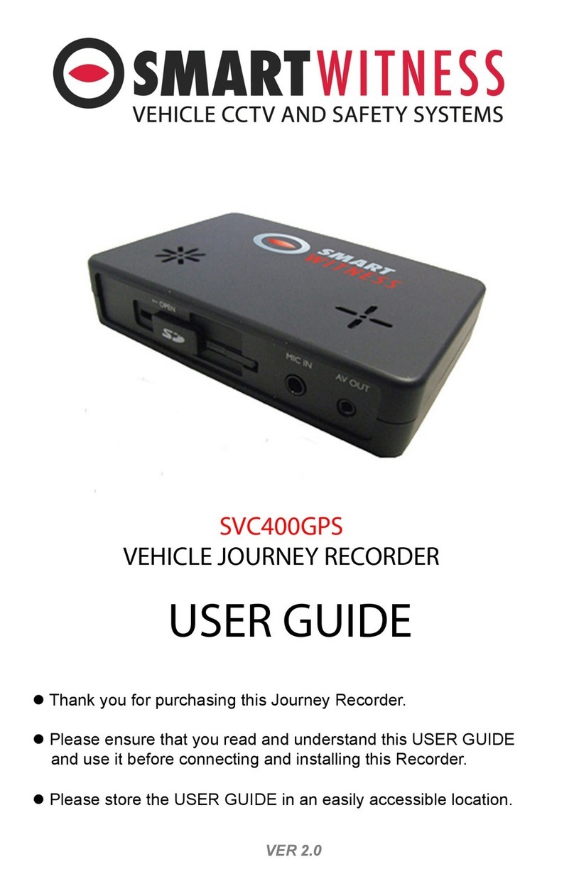
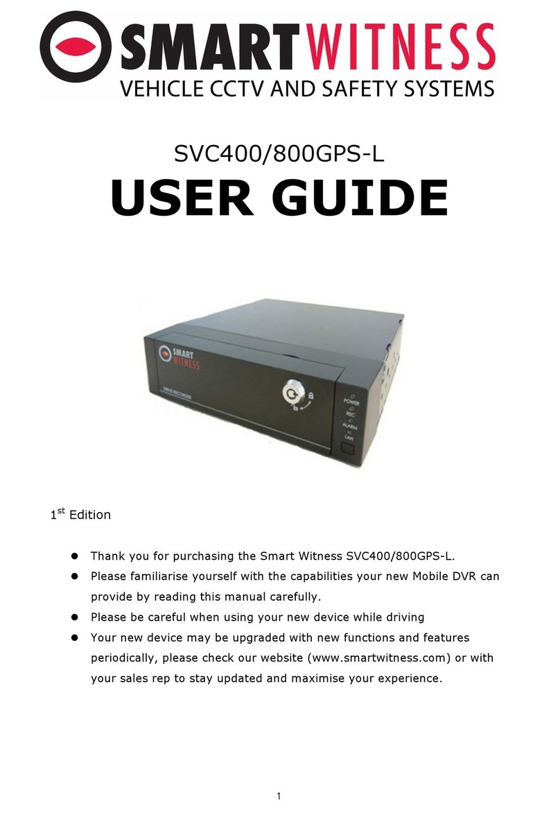
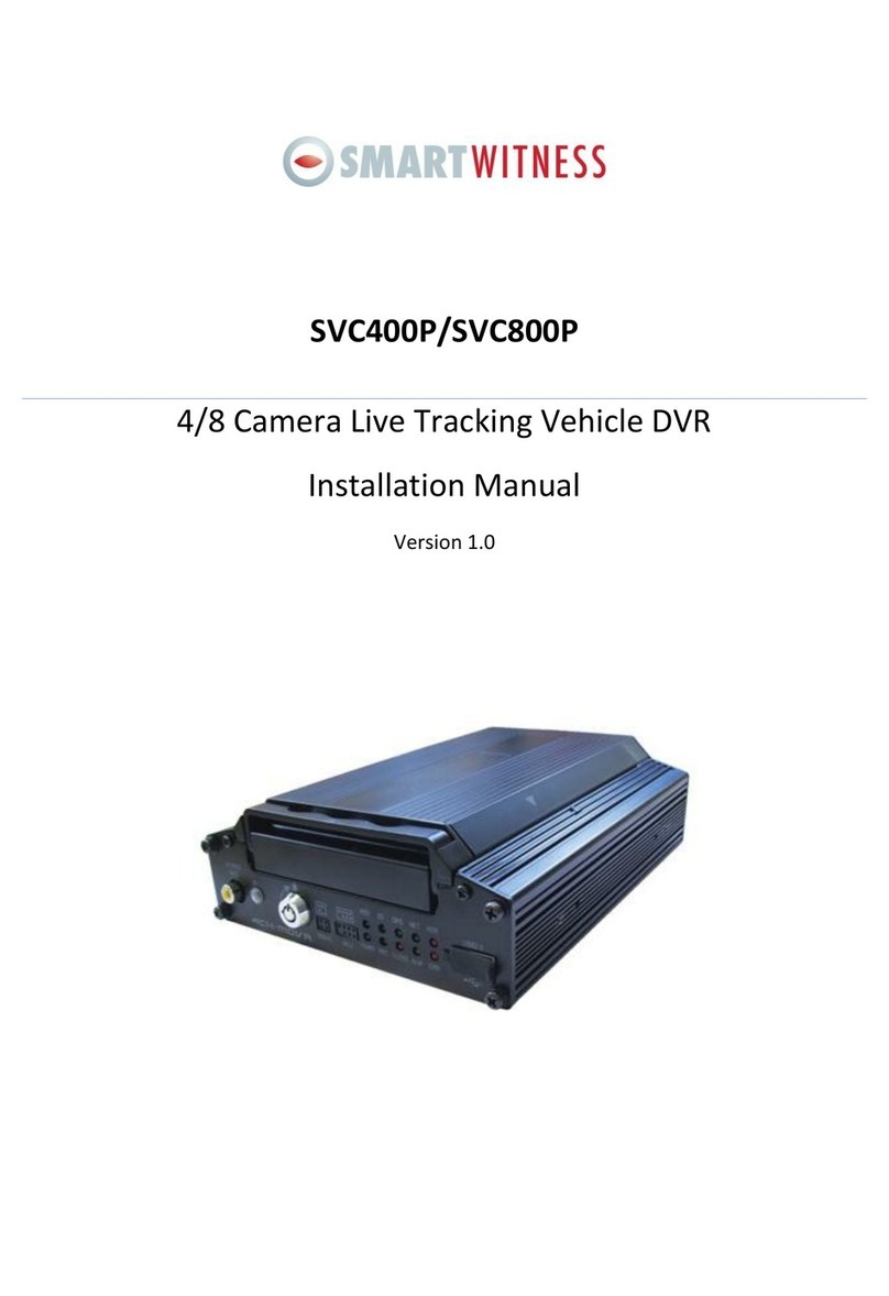
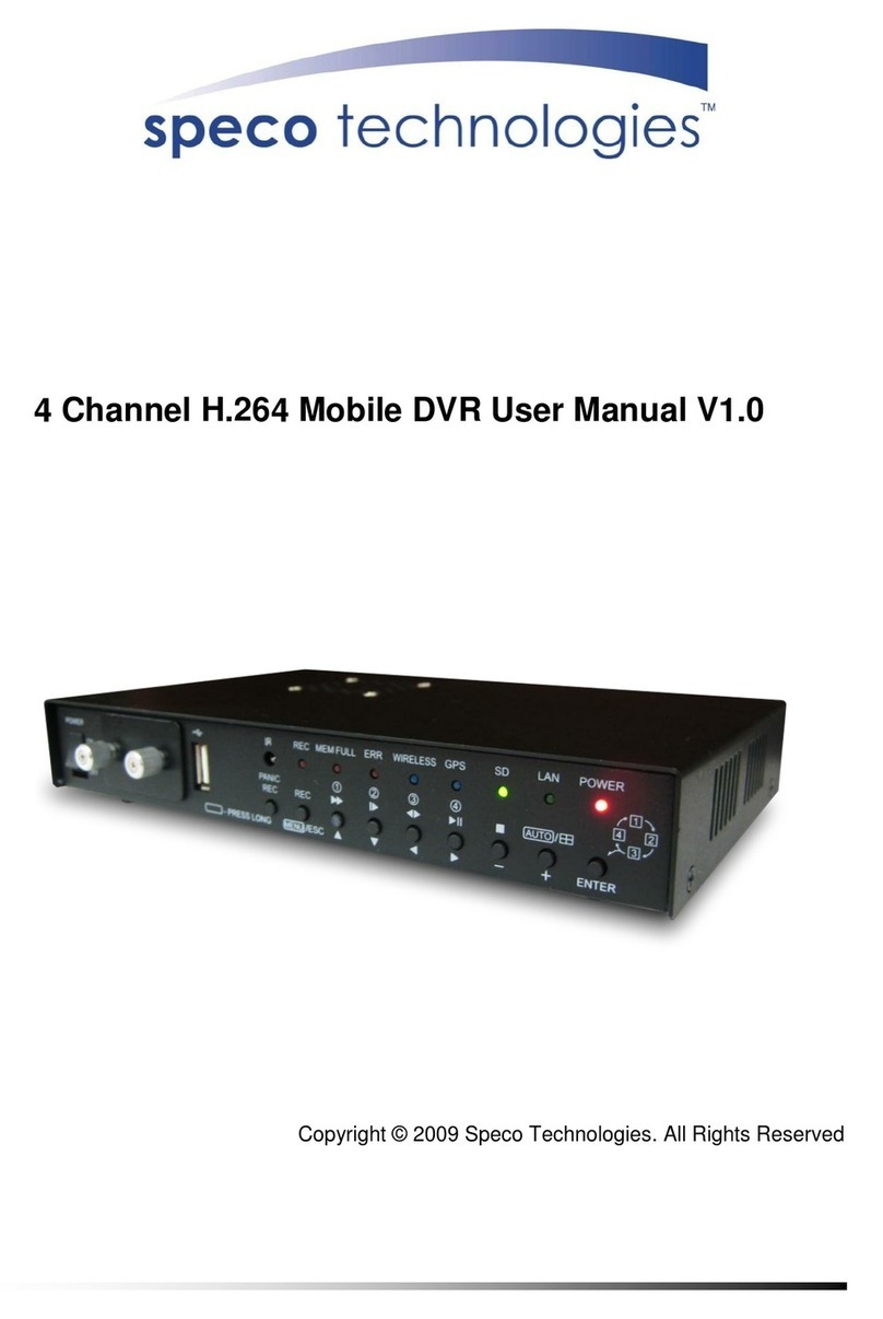
Smart Witness CRX-S User manual

Page 1 / 50
8-Channel AHD Mobile DVR
CRX-S
Model #: CRX3108
USER GUIDE
v1.0
WARNING: SmartWitness installations should be performed by a qualified individual or installation professional
only. Working with a vehicle's power system can be dangerous to both you and your vehicle. This installation is
intended only to be a guide since vehicle designs and power/input sources can vary significantly
from vehicle to vehicle.
If you need to schedule a professional installation service in the USA for your
SmartWitness device(s), please visit http://smartwitness.com/scheduleinstall and submit the online form.
All cellular-enabled CRX devices must use the installation wizard for proper onboarding and activation,
please visit http://install.smartwitness.com to register, login, and use the SmartInstall wizard.

Page 2 / 50
Notice
Any unauthorized use of this guide or its contents is prohibited. The contents may be changed without notice.
The contents of this user guide are comprehensively designed to provide adequate information to set up and
operate the purchased device. Please contact SMARTWITNESS if you have any questions or find any omissions.
If you find any missing pages in this user guide, please contact your dealer or SMARTWITNESS for a
replacement. The images and display captures are examples to help you understand this device and may differ
from what you may observe.
Limitation of use
This device is designed and manufactured for commercial use only and is not intended for use where the
failure of the device could lead to death, personal injury, or severe environmental damage. Please use
discretion when using in situations that require high precision or that may endanger life or damage
valuable assets. SMARTWITNESS does not take any responsibility for accidents in such cases.
Software License Agreement
SMARTWITNESS and its suppliers grant to the customer a nonexclusive and nontransferable license to use
the PC viewer software in object code form solely on a single central processing unit owned or leased by
Customer or otherwise embedded in equipment provided by SMARTWITNESS Customer may make one
archival copy of the Software provided Customer affixes to such copy all copyright, confidentiality, and
proprietary notices that appear on the original.
Except as expressly authorized above, the customer shall not: copy, in whole or in part, software or
documentation; modify the software; reverse compile or reverse assemble all of any portion of the
software; or rent, lease, distribute, sell, or create derivative works of the software.
Export Restrictions
SMARTWITNESS products are controlled under the Korean Export Regulations, please check all relevant
laws and codes and make sure all compliances are met before exporting.
Copyright
The use of recorded data without the expressed authorization of the owner is prohibited.
Trademark
Microsoft, Windows Vista, Windows7 are trademarks of Microsoft Corporation, registered in the US
and other countries.
Pentium is a trademark of Intel Corporation, registered in the US and other countries.
Other company and product names mentioned herein may be trademarks of their respective
companies.
Safety Guide
Please read the below safety guide carefully for your safety.
1. Power, Installation, Storage
Do not disassemble, repair, and reconstruct the device. There is a part with high voltage inside the
device.
(The manufacturer is not responsible for malfunctions of altered device which can
cause fire and electric shock.)
Please unplug the power cable from device before installation.
Please do not bend the power cable or leave on heavy object.

Page 3 / 50
Please do not bend the cables on back panel while operation.
The device overwrites when recording storage (HDD, SSD, SD Card) is full. The recorded data would
be removed while overwriting. (The manufacturer is not responsible for removed recording data from
user’s setting.)
Recording data could be damaged and unrecoverable when storages (HDD, SSD, SD Card) are out of
life cycle. Please replace the storage if the system has a warning message about storage. (The
manufacturer doesn’t take a responsibility for damaged data caused by user’s lack of negligence.)
The system status could be identified by LED in front of the unit. Please consult with your local seller
when the device has a problem.
Please place the unit on cool places and keep it away from hot, dusty, humid places.
2. Power, Installation, Storage
Please don’t install the device on place where strong magnetic or frequency is.
Please don’t put heavy loads on the device and be careful against strong shock or vibration.
Please don’t block a side hole for ventilation.
Please unplug the device instantly when there is a smell of burning.
Please check up the device periodically to maintain system’s performance.
Before reading this user guide
This guide is to provide an information necessary to use the product. It includes a brief introduction and
how to configure each part and function.
Please be noted the below before reading this documents.
The copyrights of this documents are owned by the manufacturer and reproduction is prohibited
without advance written permission.
The manufacturer is not responsible for uncertified accessories and misuse of product.
Please do not disassemble the product when it requires repair. Please consult with your local seller.
Please use storages (HDD/SSD, SD Card) certified by manufacturer. You can consult the compatibility
with your local seller.
Warning
System Shut Down
Forced shutdown during operation could damage to storage and system. Please do not pull out the
power cable or turn off the power switch on back side while operation.
Operating Temperature
The device may not boot up after keeping it on low temperature below the specification for a long
time. The device will automatically boot up when the temperature reaches to operating range after
power supplies.
Security and Privacy
The device could be configured by local menu and recorded data could be played by local control.
Please set up local password for security and privacy. Please keep the password securely.

Page 4 / 50
INDEX
1. Introduction.............................................................................................................................................................................5
2. System Components............................................................................................................................................................6
3. Product .....................................................................................................................................................................................8
3-1 Front Panel...................................................................................................................................................................8
3-2 Rear Panel.....................................................................................................................................................................9
4. Monitoring ............................................................................................................................................................................ 10
4-1 System Start ............................................................................................................................................................. 10
4-2 System Shutdown.................................................................................................................................................. 10
5. Live Screen............................................................................................................................................................................. 10
5-1 Live Screen Icon...................................................................................................................................................... 10
5-2 Icons ............................................................................................................................................................................. 11
5-3 OSD Information.................................................................................................................................................... 12
5-4 Screen Layout.......................................................................................................................................................... 13
5-5 System Information.............................................................................................................................................. 13
5-6 LED Status.................................................................................................................................................................. 14
6. System Menu........................................................................................................................................................................ 15
6-1 DEVICE......................................................................................................................................................................... 17
6-1-1 CAMERA ....................................................................................................................................................... 17
6-1-2 SIGNAL .......................................................................................................................................................... 18
6-1-3 G-SENSOR.................................................................................................................................................... 18
6-1-4 EXT DEVICE ................................................................................................................................................. 19
6-1-5 EMS ................................................................................................................................................................. 20
6-1-6 MISC ............................................................................................................................................................... 21
6-2 RECORD ...................................................................................................................................................................... 22
6-2-1 MISC ............................................................................................................................................................... 23
6-2-2 CHANNEL SETUP...................................................................................................................................... 23
6-2-3 SD DUAL RECORD.................................................................................................................................... 24
6-3 EVENT .......................................................................................................................................................................... 26
6-3-1 MOTION........................................................................................................................................................ 26
6-3-2 ALARM IN.................................................................................................................................................... 27
6-3-3 SIGNAL .......................................................................................................................................................... 28
6-3-4 G-SENSOR.................................................................................................................................................... 28
6-3-5 SPEED / V-LOSS ........................................................................................................................................ 29
6-4 SYSTEM....................................................................................................................................................................... 30
6-4-1 DATE/TIME .................................................................................................................................................. 31
6-4-2 USER MANAGEMENT............................................................................................................................. 31
6-4-3 SERVICE MENU.......................................................................................................................................... 32
6-4-4 NETWORK.................................................................................................................................................... 41
6-4-5 HAZARD ....................................................................................................................................................... 44
7. SEARCH and PLAYBACK.................................................................................................................................................. 45
7-1 CALENDAR SEARCH ............................................................................................................................................. 45
7-2 LOG SEARCH ............................................................................................................................................................ 45
7-3 PLAYBACK ................................................................................................................................................................. 46
8. BACKUP................................................................................................................................................................................... 47
8-1 VIDEO BACKUP ....................................................................................................................................................... 47
8-2 DRIVE DATA BACKUP .......................................................................................................................................... 49
TECHNICAL SPECIFICATIONS............................................................................................................................................ 50

Page 5 / 50
Introduction
CRX3108 is a mobile digital video recorder which can records up to 8 channel camera inputs and compress
the video data with H.264 codec. It can also record 8 channel audio signal with G.711 codec and save
video/audio data to storages (HDD/SSD, SD Card).
With network connection, it sends video and images to server and the user can access to the device via
network.
Simultaneous recording and playback up to 8CH video/audio
Supported resolution 5M/4M/3M/FHD(1080P)/HD(720P)/WD1/D1/HD1/CIF
Dual recording with HDD/SSD, SD Card
Auto recovery, auto format, overwriting on HDD/SSD
HDD/SSD/SD Card status monitoring
Local playback and backup
Convenient search function (Calendar Search, Log Search)
Various recording events (Continuous, Event recording, Alarm, G-sensor, Overspeed)
8 Alarm-inputs, 2 Alarm-outs
Convenient Local UI
PC Viewer software for playback and search

Page 6 / 50
2. System Components
Please check you have all accessories including the package. The components may vary based on your
region and seller. Storage might not be included in the package. Please consult with your local seller.
QTY
Name
Description
Picture
1
CRX3108
CRX3108 Main Unit
1
CRX-GPS
GPS Module
1
RH500
Storage Case (HDD/SSD)
1
&
2
MPR11020901
(REAR)
&
MPR11021001
(SIDE)
Installation Brackets
(Side x 2, Rear x 1)
6
&
9
PAN+ 05*08(Black)
&
PAN+ 04*08(Black)
Screws for Brackets
2
MKY03
Locking Keys for Storage

Page 7 / 50
QTY
Name
Description
Picture
2
MKY02
Locking Keys for Front Door
2
CRX3-WH041-1
Camera Input Cable (4CH x 2)
1
BRX-WH061
Video Out Cable
1
CRX3-WH020-1
Power Cable
1
CRX3-WH062-1
Digital IO & A/V Out
1
CRX3-WH100-1
Car Signal Cable

Page 8 / 50
3. Product
3-1 Front Panel
#
Name
Description
①
Front Lock
Front Door Locking Cover
②
LED
[POWER]
Power On/Off Status
[REC]
Recording Status
[ALARM]
System Warning Status
[LAN]
Network Connection Status
IR Receiver
IR Receiver for Remote Controller
③
Control Panel
[SER] Search, Backup
[CH] Live Screen Layout Change
[ESC] Back to previous screen
[MENU] Menu or Confirm
[FN] Functions
[STA] Status
①
②
③
⑤
⑦
⑧
④
⑥

Page 9 / 50
[∧∨<>] Arrow Keys
④
HDD/SSD Tray
HDD/SSD cannot be removed while HDD/SSD key lock is ON.
Please remove the storage when all LED turned off.
⑤
HDD/SSD key lock
You can turn on the device by HDD/SSD key lock.
⑥
SD Card Slot
SD Card slot should be locked for operation. Please unlock the
slot first when you remove SD card.
⑦
Video Out
You can connect external monitor for live screen.
⑧
DC 12V Output
DC 12V power output for external device
3-2 Rear Panel
#
Name
Description
①
DC IN (Main Power)
Please connect each BAT+, BAT-, ACC+.
②
CS (Car Signal)
Please connect a cable for each car signal.
(LEFT, RIGHT, BRAKE, REVERSE, SPEED, RPM)
③
S1, S2 (Serial Port)
You can connect external devices.
④
ON/OFF (Main Power Switch)
Please turn off the switch while installation.
⑤
DC 12V OUT
You can use 12V output for external devices.
⑥
DIGITAL IO/AV OUT
Digital IO and AV out cables could be connected for 8 alarm
inputs / 2 alarm output and Audio/Video output.
⑦
AV IN (1~4) , AV IN (5~8)
Camera 1~4 : Video/Audio and 12V power supply
Camera 5~8 : Video/Audio and 12V power supply
⑧
LAN
RJ45 connector for network
⑨
USB
USB type external devices could be connected.
⑩
DIP Switch
Switch 1 (Power-on Delay)
UP (boot-up delay 1sec) / DOWN (boot-up delay 5 sec.)
Switch 2 (Boot-up Temperature)
UP (boot-up above -20°C / DOWN (boot-up above 0°C)
⑪
GPS
GPS module connector
⑤
⑥
⑦
⑧
⑨
①
②
③
④
⑪
⑩

Page 10 / 50
4. Monitoring
4-1 System Start
1. After installation, the system boots up when HDD/SSD key lock turns on.
2. It takes about 30 seconds for boot-up and you can see the below screen after boot-up.
4-2 System Shutdown
1. The system is going to be shut down when HDD/SSD key lock turns off.
2. Please wait until all front LEDs are turned off before you remove HDD/SSD. The recorded data could
be damaged when HDD/SSD is removed before shutdown.
5. Live Screen
5-1 Live Screen Icon
Notes
1. You can control the main power by vehicle’s main power switch or ignition (ACC)
according to power supply connection.
2. Occasionally, it takes more than 1 minute for boot-up. This is a normal operation
to check HDD/SSD.
3. [REC] LED is not turned on without HDD or SSD installed.
4. There would be a problem on camera or storage when [ALARM] RED LED is turned
on or blinking. Please consult with your local seller for further support.
⑤
①
②
③
④
⑥
⑦
⑧

Page 11 / 50
#
Name
Description
①
Camera Name
You can set up the camera name. (Default CAM1 ~ CAM8)
②
Alarm-in, Alarm-out
8 Alarm Inputs, 2 Alarm Outputs, G-sensor
③
Storage Capacity
HDD/SSD (Left), SD Card (Right)
④
Speed
Vehicle’s current speed
⑤
Network
Network connection status
⑥
System Warning
System warning is displayed.
⑦
Date/Time
Displays current date and time.
⑧
Camera Status
Displays each camera’s status
Notes
Alarm LED is turned on when system warning( ) or
video loss( ) icon is displayed.
Please check the system for recording and camera status
when you see the icons like or .
5-2 Icons
Icon
Description
Video Loss or Camera Disconnection
Continuous Recording in Progress
Event Recording in Progress
Motion Detection
Audio Recording in Progress
System Warning
5M resolution camera connected
4M resolution camera connected
3M resolution camera connected
FULL HD resolution camera connected
HD resolution camera connected
SD resolution camera connected

Page 12 / 50
Alarm-in, Alarm-out, G-Sensor
Alarm-in is activated
Alarm-out is activated
G-sensor is detected
3G/LTE Status
Initializing – Initializing Fail - Communication Fail - Connection
Ready – Communication in Progress
WIFI Status
Initializing – Initializing Fail - Communication Fail - Connection
Ready – Communication in Progress
LAN Status
Initializing – Initializing Fail - Communication Fail - Connection
Ready – Communication in Progress
5-3 OSD Information
You can choose OSD information displayed on live screen.
There are 4 OSD screen mode and you can change it by [ESC] button.
<All OSD information> <Camera Name, System Warning, Storage Capacity, Date/Time>
<System Warning, Storage Capacity, Date/Time> <OSD turned off>

Page 13 / 50
5-4 Screen Layout
There are 7 screen layouts and you can change it by [<] button on live screen.
Full Screen
The system displays full screen from CAM1 to CAM8 sequentially by [CH] button on live screen. You can
change the screen layouts from full screen to layout screen by [<] button.
The below is the layout changing sequence.
5-5 System Information
The system displays information screen when push [STA] button on live screen.

Page 14 / 50
Item
Description
S/W Version
Displays system S/W version
H/W Version
Displays system H/W version
Network
Displays network connection status
MAC Address
Displays system MAC address.
GPS
Displays GPS information
[Notes] Latitude/Longitude is displayed when GPS is working
properly.
Alarm in / Alarm Out
Displays Alarm-in / Alarm-out status.
[Notes] From left, 8 alarm-in and 2 alarm-out are displayed.
The icon could be changed from 「-」 to 「1~8」 when
alarm is activated.
Pulse
Displays pulse speed and RPM information.
(This information could be displayed when SPEED and RPM
cables are connected to vehicle.)
Car Signal
Displays car signal status.
(The cables need to be connected with vehicle’s LEFT, RIGHT,
BRAKE, REVERSE signal)
GSNR, GYRO
GSNR (G-sensor’s X/Y/Z value)
GYRO (GYRO sensor’s X/Y/Z value)
System Warning
Displays system warning message
5-6 LED Status
LEDs on front panel indicates the system’s operation status about power supply, recording status, alarm,
and communication.
LED
Status
Operation

Page 15 / 50
POWER
(Green)
Off
System shutdown
Steady
System start
REC
(Orange)
Off
Not Recording
Steady
Recording in Progress
Blinking
HDD/SSD Format, Recovery
ALARM
(Red)
Off
Normal Operation
Steady
Storage Error, Storage Full
Blinking
System Warning
LAN
(Orange)
Off
Network Not Available, No USB Dongle or No SIM Card
Steady
Network Connection Normal
Blinking
Device Error or Network Error
SD REC
(Green)
Off
SD Card is not in Recording, SD Card slide is not locked.
Steady
SD Card Recording in Progress
Blinking
SD Card Operation for Backup, Setting Upload/Download, Upgrade,
Format, Recovery
SD NG
(Red)
Off
No Recording Setup on SD Card (SD Card Normal)
Steady
SD Card has recording setup (SD Card error or full)
6. System Menu
Entering main menu
You can enter the device main menu by [MENU] button on live screen. Password is required to enter the
menu and you can skip it by [MENU] button if no password is set up.

Page 16 / 50
Controlling menu screen
System menu consists of DEVICE, RECORD, EVENT, and SYSTEM. You can move the cursor by arrow button
[∧∨<>]. You can enter each menu by [MENU] button and [ESC] button for previous menu. [MENU] button
is also used for confirming the setting in menu screen.

Page 17 / 50
6-1 DEVICE
You can set up camera, signal, G-sensor, external devices, EMS and miscellaneous.
6-1-1 CAMERA
You can set up each camera’s video, name, brightness, contrast, transformation, and controls.
CAMERA : You can select the camera you want to set up. (1~8)
VIDEO : You can enable or disable a camera.
CAMERA TITLE : You can name a camera with alphabet and numbers up to 10 characters.
BRIGHTNESS:You can set up the brightness of each camera from 10% to 100%.
CONTRAST:You can set up the contrast of each camera from 10% to 100%.
TRANSFORMATION : You can set up the video inversion vertically and horizontally.
CONTROL : You can control the camera’s set up menu.
Warning
1. Video OFF channel will be displayed on live screen but could not be recorded.
2. Video loss icon( ) will be displayed and alarm LED (RED) will be blinking when Video ON
channel doesn’t send video signal properly.

Page 18 / 50
6-1-2 SIGNAL
You can set up the function related to car pulse, RPM, and pulse signal types.
CARPULSE TYPE : You can select type 1 to 25. Please check the vehicle’s car pulse type.
CARPULSE STD : You can select the standard among 「JIS 4W/JIS 2W
3W/SAE/DIN/BNA/MANUAL」. Please check the vehicle’s car pulse standard.
CARPULSE STD VALUE : You can set up a standard value for the vehicle’s car pulse type and
standard.
RPM PULSE TYPE : You can select RPM type from 1 to 10 according to the vehicle’s specification.
PULSE SIGNAL : You can set up Pull-up, Pull-down, and none for pulse signal type.
6-1-3 G-SENSOR
3. Please change VIDEO setting to OFF for channels which are not connected to cameras. If the
channel without cameras are set to ON, Alarm LED keeps blinking.

Page 19 / 50
You can set up the initial calibration of G-sensor according to installation.
You can change the X/Y/Z value among 0/90/180/270 degrees.
Please check set up screen is same with actual installation.
6-1-4 EXT DEVICE

Page 20 / 50
You can set up external device connected to the product.
DEVICE PORT : Please select the serial port connected to external device 1 or 2.
(OFF, S2, S3, S4, S5, S6)
DEVICE TYPE : Please select the type of external device 1 or 2.
(D-TEG, ATBS OBDⅡ, ELM327 OBDⅡ, OMNICOMM, DL550A, ROADSCOPE7)
GPS : Please select the device to receive GPS signal.
SPEED : Please select the device to receive SPEED information.
RPM : Please select the device to receive RPM information.
SIGNAL : Please select the device to receive signal information.
RECORD TEXT : You can enable/disable the function to record text from external device.
SEND HEALTH : You can enable/disable to send health check to external device.
6-1-5 EMS
This manual suits for next models
1
Table of contents
Other Smart Witness DVR manuals

Smart Witness
Smart Witness SVC420/820GPS User manual

Smart Witness
Smart Witness SVC400P User manual

Smart Witness
Smart Witness SVC400L User manual

Smart Witness
Smart Witness CP4S-NA User manual

Smart Witness
Smart Witness SVC400 User manual

Smart Witness
Smart Witness SVC400L User manual

Smart Witness
Smart Witness SVC400GPS-L User manual

Smart Witness
Smart Witness SVC400GPS User manual