SmartSafe iSmartEV OM210 User manual

iSmartEV OM210 User Manual
w
ww.newsmartsafe.com
I
Copyright Information
Copyright © 2021 by SHENZHEN SMARTSAFE TECH CO.,LTD. All rights
reserved. No part of this publication may be reproduced, stored in a retrieval
system, or transmitted in any form or by any means, electronic, mechanical,
photocopying, recording or otherwise, without the prior written permission of
SMARTSAFE.
Neither SMARTSAFE nor its affiliates shall be liable to the purchaser of this unit
or third parties for damages, losses, costs, or expenses incurred by purchaser
or third parties as a result of: Accident, misuse, or abuse of this unit, or
unauthorized modifications, repairs, or alterations to this unit, or failure to strictly
comply with SMARTSAFE operating and maintenance instructions.
SMARTSAFE shall not be liable for any damages or problems arising from the
use of any options or any consumable products other than those designated as
Original SMARTSAFE Products or SMARTSAFE Approved Products by
SMARTSAFE.
All information, specifications and illustrations in this manual are based on the
latest information available at the time of printing. SMARTSAFE reserves the
right to make changes at any time without prior written or oral notice.
Trademark Information
is a registered trademark of SHENZHEN SMARTSAFE TECH
CO.,LTD. in China and other countries. All other SMARTSAFE trademarks,
service marks, domain names, logos, and company names referred to in this
manual are either trademarks, registered trademarks, service marks, domain
names, logos, company names of SMARTSAFE or are otherwise the property of
SMARTSAFE or its affiliates. In countries where any of the SMARTSAFE
trademarks, service marks, domain names, logos and company names are not
registered, SMARTSAFE claims other rights associated with unregistered
trademarks, service marks, domain names, logos, and company names. Other
products or company names referred to in this manual may be trademarks of
their respective owners. You may not use any trademark, service mark, domain

iSmartEV OM210 User Manual www.newsmartsafe.com
II
name, logo, or company name of SMARTSAFE or any third party without
permission from the owner of the applicable trademark, service mark, domain
name, logo, or company name. You may contact SMARTSAFE by visiting the
website at www.newsmartsafe.com, or writing to SHENZHEN SMARTSAFE
TECH CO.,LTD., 3310, Building 11, Tianan Cloud Park, Bantian Street,
Longgang District, Shenzhen, Guangdong, China, to request written permission
to use Materials on this manual for purposes or for all other questions relating to
this manual.
To avoid personal injury, property damage, or accidental damage to the product,
please read all the information in this chapter before using the product.
Safety Warning
Please read the following safety precautions carefully to avoid personal injury
and damage to this product or other connected products. To avoid possible
injury and danger, this product shall only be used within the specified range.
Be careful when handling equipment.
Do not drop, bend, puncture, insert foreign objects or place heavy objects on the
device, which may damage the internal wearable components.
Avoid fire or personal injury.
Only authorized professional personnel shall perform maintenance.
Connect and disconnect properly.
Do not unplug when the probe or test end is connected to the voltage
source.
Before connecting the probe to to the circuit under test, please connect it to
the Oscillograph Multimeter. Disconnect the probe from the circuit under test
before disconnecting the probe from the test instrument.
Use the correct probe. To avoid excessive current impact, use the correct
rated probe for the measurement.
Avoid circuit exposure. Do not touch any exposed connectors and
components when the power is on.
Do not operate the product when you suspect a malfunction. If you suspect

iSmartEV OM210 User Manual
w
ww.newsmartsafe.com
III
a product malfunction, have it checked by qualified maintenance personnel.
Keep ventilation.
Keep your product properly ventilated.
Do not operate in a humid environment.
Do not operate in a flammable or explosive environment.
Keep the surface of the product clean and dry.
Do not disassemble or modify the equipment.
The equipment is a sealed unit with no end-user serviceable parts inside. Only
authorized maintenance agency or authorized technicians shall perform internal
repairs. Attempting to disassemble or modify the unit will void the warranty.
Do not attempt to replace the internal battery.
Only authorized maintenance agency or authorized technicians shall replace the
internal rechargeable batteries.
Precautions for operation of automotive ECU.
After the ignition switch is on, do not disconnect the vehicle’s internal
electrical device at will to avoid damage to the ECU or equipment.
Do not place magnetic objects close to the computer to avoid circuits and
components failure in the ECU.
Before performing welding work on the vehicle, disconnect the ECU system
power first.
When performing repair work close to computers or sensors, special care
shall be taken to avoid damaging the ECU and sensors.
When disassembling and installing programmable read-only memory, the
operator shall wear a grounding metal band with one end wrapped around wrist
and the other end clipped to the vehicle body, so as to avoid ECU circuit failure
caused by static electricity.
Ground the ECU harness connector reliably to avoid damage to the
electronic components such as integrated circuits inside the ECU.


iSmartEV OM210 User Manual
w
ww.newsmartsafe.com
V
Contents
1. Packing List ................................................................................................... 1
2. Product Introduction ..................................................................................... 2
2.1 Overview ..................................................................................................... 2
2.2 Composition ................................................................................................ 3
2.3 Technical Parameters ................................................................................. 4
3. Oscilloscope Operation................................................................................ 6
3.1 Preparation before measurement ............................................................... 6
3.1.1 Start device and APP ......................................................................... 6
3.1.2 Communication Setting....................................................................10
3.1.3 Automatic Calibration ....................................................................... 10
3.1.4 Connection .......................................................................................11
3.2 How to operate ..........................................................................................12
3.2.1 Select channel..................................................................................12
3.2.2 Channel attributes and trigger setting .............................................. 12
3.2.3 Automatic Setting .............................................................................16
3.2.4 Menu Operation ............................................................................... 16
3.2.5 Car Test ........................................................................................... 19
3.2.6 Cursor Measurement ....................................................................... 20
3.2.7 Quick save....................................................................................... 21
3.2.8 REF (Reference) Waveform .............................................................21
4. Multimeter Operation ...................................................................................23
4.1 Preparation before measurement ............................................................. 23
4.1.1 Start device and APP ....................................................................... 23
4.1.2 Communication Setting....................................................................23
4.2 How to operate ..........................................................................................24

iSmartEV OM210 User Manual www.newsmartsafe.com
4.2.1 Voltage Measurement ...................................................................... 24
4.2.2 Current Measurement...................................................................... 26
4.2.3 Resistance Measurement ................................................................ 27
4.2.4 Diode Measurement .........................................................................28
4.2.5 On-off Measurement ........................................................................ 28
4.3 Detection Examples .................................................................................. 29
4.4 Precautions ............................................................................................... 30
5. Maintenance ................................................................................................. 32
Warranty........................................................................................................... 33

iSmartEV OM210 User Manual
w
ww.newsmartsafe.com
1
1. Packing List
The following accessories are for reference only. Please consult from the local
agency or check the package list supplied with this tool together.
No. Name Q'TY Reference Picture
1 iSmartEV OM210 1
2 Power Adaptor 1
3USB Cable
(Type-B) 1
4 Oscilloscope Test Clip 2
5 Pin Kit 1
6Crocodile Chuck
Black 2

iSmartEV OM210 User Manual www.newsmartsafe.com
2
Crocodile Chuck
Red 2
7
Multimeter Test Lead
Black 1
Multimeter Test Lead
Red 1
8 User Manual 1 -
9 Packing List 1 -
2. Product Introduction
2.1 Overview
iSmartEV OM210 is a new energy test equipment developed by
SmartSafe, which integrates oscilloscope and multimeter functions. The tool
needs to be used together with detection tool (such as iSmartEV P01).
The oscilloscope is mainly used to measure voltage signals and analyze
the form of electronic signals. Automobile repair technicians can quickly judge
automobile electronic equipment and circuit failure by observing the waveform
of the whole signal. Oscilloscope scanning speed is far greater than the
frequency of the such automobile signals, usually 5~10 times of the measured

iSmartEV OM210 User Manual
w
ww.newsmartsafe.com
3
signal. The automobile oscilloscope can not only capture circuit signals quickly,
but also display these waveforms at a slower speed, so as to observe and
analyze at the same time. It can also store and record the tested signal
waveform, and observe the fast signal that has occurred through playback,
which greatly facilitates fault analysis.
The multimeter mainly measures voltage, current and resistance. It can
judge whether the part is good or not and whether the circuit is complete by
simple measurement.
2.2 Composition
No. Name Description
1Fuse
*2 A10A current input terminal
*3 mAμA Milliampere/Microampere (Less than
400ma) current input terminal
*4 COM Negative common terminal
*5 V/Ω Voltage/Resistance and other input
terminals
*Note: The above are related interfaces of multimeter function.

iSmartEV OM210 User Manual www.newsmartsafe.com
4
6Handle
7Power Indicator
Red flashing indicates insufficient
power; If the red light is normally on, it
indicates that charging is in progress; A
constant green light indicates that the
battery is normal or fully charged.
8State Indicator Green light indicates normal operation.
9Wireless Indicator
The red flashing indicates that the
wireless connection is in progress; The
green light indicates that the wireless
connection is normal.
10 Indicator Green light indicates normal operation.
11 CH1 Oscilloscope Channel 1
12 CH2 Oscilloscope Channel 2
13 Communication/Charging
Jack
1. When charging, use the power
adaptor and USB cable to charge the
Oscillograph Multimeter.
2. When transmitting data, use USB
cable to connect the Oscillograph
Multimeter and detection equipment.
Note: The detection equipment cannot
supply power to the Oscillograph Multimeter.
Please charge the Oscillograph Multimeter
before use.
14 Power Button Press and hold this key to turn on/off.
2.3 Technical Parameters
When used as oscilloscope:
Item Specification Parameters
Number of Channels 2
Bandwidth 10MHz
Maximum Real-time 100Mbps

iSmartEV OM210 User Manual
w
ww.newsmartsafe.com
5
Sampling Rate
Time Base Range 1us/div~10s/div, step by 1 ~ 2 ~ 5 times
Sampling Mode Common sampling, peak detection, average
value
Storage Depth 1M
Input Coupling DC, AC and Grounding
Input Impedance 1MΩ±2%
Input Capacitance 20pF (maximum)
Vertical Sensitivity 2mV/div~5V/div
Vertical Resolution 8bits
Maximum Input Voltage 40V peak (DC + AC peak)
Probe Attenuation
Coefficient 1X, 10X (probe support required)
Trigger Type Edge trigger, pulse width trigger
Trigger Mode Automatic, normal, single time
Automatic Measurement Peak, AVG Value, Max Value, Min Value,
Frequency, Cycle
When used as multimeter:
Item Specification Parameters
DC Voltage Automatic range, test range: ±600V
AC Voltage Automatic range, test range: ±600V
DC Current
Automatic range, test range: ±10A
(external sensors are required for large
range currents)
AC Current
Automatic range, test range: ±10A.
Average value measurement (external
sensors are required for large range
currents)

iSmartEV OM210 User Manual www.newsmartsafe.com
6
Resistor Automatic range, test range: 0Ω~6MΩ
Diode 0~2.0V
On-off Detection Sound when it is lower than 50Ω
3. Oscilloscope Operation
3.1 Preparation before measurement
3.1.1 Start device and APP
1. Long press the Power button on the oscillograph multimeter to turn on the
device.
2. Tap Oscilloscope in the main interface of “Toolbox” function of the detection
tool (such as iSmartEV P01) to start the App.

iSmartEV OM210 User Manual
w
ww.newsmartsafe.com
7
No. Description Operation Prompt
1
Menu
Include the following options:
Measure: provide 6 parameter measurement
items.
Save: Set the save format and save path of
channel waveform.
Show: Set the waveform display style.
User Settings: Provide functions such as data
clearing, oscilloscope setting and automatic
calibration.
About: Display the specific information of the
program.
Click once to expand the
submenu. Click again to retract
the submenu.
2
Car Test
It provides various vehicle related test content
(such as circuit, sensor, actuator, commnication
test, combined test) and corresponding test
connection methods.
Click once to expand the
submenu. Click again to retract
the submenu.
3Trigger
Used to set trigger channel and trigger type.
Click once to expand the
submenu to set channels and
conditions. Click again to retract
the submenu.
4Horizontal Trigger Position Mark
Press and hold and drag left
and right to adjust the horizontal
trigger position.
5
Save
It can quickly save the measurement waveform
of the currently opened channel.
To change the save path and file
type, tap Menu -> Save to set.
6Horizontal Setting
Control the horizontal time base.
Click once to expand the
horizontal time base option and
select the appropriate time base
value.
7
Single Trigger
Capture a trigger, complete the acquisition, and
then stop.
8Auto
iSmartEV OM210 User Manual www.newsmartsafe.com
8
Click to enable the automatic range function.
When the automatic range function is enabled,
the oscilloscope will automatically set various
parameters, including vertical scale, horizontal
time base and trigger level. When the signal is
connected, these parameters will change
automatically, and there is no need to operate
again after the signal changes. The oscilloscope
will automatically recognize and make
corresponding changes.
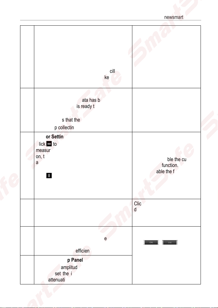
9
Wait/Run/Stop
Wait: All pre-triggered data has been obtained,
and the oscilloscope is ready to receive the
trigger.
Run: Indicates that the oscilloscope is running.
Stop: Stop collecting data.
10
Cursor Settings
Click to turn on/off the horizontal
measurement cursor switch. When it is turned
on, two reference lines named Y1 & Y2 will
appear in the waveform display area of the
screen.
Click to turn on/off the vertical measurement
cursor switch. When it is turned on, two
reference lines named X1 & x2 will appear in the
waveform display area of the screen.
Click once to enable the cursor
measurement function. Click
again to disable the function.
11 Connection Status Button
Click to search and connect
devices, and "Connected" will be
displayed after successful
connection.
12
Channel 1 Setup Panel
Control the amplitude of the displayed signal.
You can set the inversion, coupling mode and
probe attenuation coefficient.
When the channel is enabled,
click /once to
disable the channel and hide the
channel setting menu.
Click it again to enable the
channel and expand the channel
setting menu.
13
Channel 2 Setup Panel
Control the amplitude of the displayed signal.
You can set the inversion, coupling mode and
probe attenuation coefficient.

iSmartEV OM210 User Manual
w
ww.newsmartsafe.com
9
14 REF (Reference) Channel Setting
Set the reference channel.
In the channel setting panel area,
press and slide the screen up to
call up the REF reference
channel button, and click this
button to call up the reference
channel setting menu.
15 Edge Trigger Level Identification
Press and hold the icon to drag
up and down to set the trigger
level.
16 Channel 2 Voltage Scale Click+/- to adjust the interval
value of channel 2 voltage scale.
17 Channel selection button
Click to select the target channel.
Click once to call up the channel
(only the opened channels are
displayed) selection pop-up
window. Click again to close the
window.
18 / or / Fine-tuning button
When the horizontal cursor is
turned on, the fine-tuning buttons
are displayed as and . If
the vertical cursor is turned on,
the fine-tuning buttons are
displayed as and .
19 Horizontal Time Base
20 Measured Value Display Area It can be called up through Menu
-> Measure.
21
Channel 2 Mark
Indicate the reference point of the displayed
waveform. If there is no mark, the channel is
disabled and will not be displayed.
22
Channel 1 Mark
Indicate the reference point of the displayed
waveform. If there is no mark, the channel is
disabled and will not be displayed.
23
REF(Reference) Channel Mark
Indicate the reference point of the displayed
waveform. If there is no mark, the channel is
disabled and will not be displayed.

iSmartEV OM210 User Manual www.newsmartsafe.com
10
24 Waveform Display Area
25 Channel 1 Voltage Scale Click+/- to adjust the interval
value of channel 1 voltage scale.
3.1.2 Communication Setting
The main connection methods between the Oscillograph Multimeter and the
detection tool are Wi-Fi communication and USB wired communication.
Wi-Fi communication
Click “Connect” to search for and connect the oscilloscope device. After
successful connection, the detection device screen will show the connection
status and the Wireless indicator on the Oscillograph Multimeter will light up in
green.
USB communication
When connecting the oscilloscope to the detection equipment via USB cable,
the system will automatically switch to USB communication mode. At this time,
the Wireless indicator on the Oscillograph Multimeter will be off.
3.1.3 Automatic Calibration
The auto-calibration program optimizes the oscilloscope signal path with
maximum measurement accuracy. The user can run this program at any time,
but shall run it if the ambient temperature changes by 10°C or more. In order to
calibrate more accurately, the oscilloscope must be powered on and warmed up
for 20 minutes before auto-calibration. The calibration mainly includes the
calibration of the analog channel, the trigger voltage in the trigger circuit and the
horizontal baseline shift nonlinearity.
Note: During automatic calibration, please ensure that no signal is input to the input

iSmartEV OM210 User Manual
w
ww.newsmartsafe.com
11
terminal of CH1/CH2, otherwise the instrument may be damaged.
Tap Menu -> User Settings -> Automatic calibration.
Click OK on the window below to start calibration, and the message
“Calibration...Please wait.” will appear on the screen. When the automatic
calibration is finished, the “Calibration Successful” pop-up box will appear on the
screen.
3.1.4 Connection
When testing sensor:
1. Connect the BNC connector end of the oscilloscope test clip to channel
CH1/CH2 (select the channel number and quantity of channels as needed),
connect the black connector of the other end to the black pin or black alligator
clip, and connect the red connector to the other color pin or red alligator clip.

iSmartEV OM210 User Manual www.newsmartsafe.com
12
2. Connect the black pin or black alligator clip to the ground wire port of the
vehicle sensor, and connect the other color pin or red alligator clip connected
with the red connector to the signal terminal of the vehicle sensor.
3.2 How to operate
3.2.1 Select channel
The system channels are CH1 (channel 1), CH2 (channel 2) and REF
(reference channel), please select channels as follows:
A. Select channels with the channel button on the right side of the screen.
B. Click to select target channel. This method is only applicable to
opened channels.
Note: Each channel and waveform is marked with a different color for better comparison
and distinction by users.
The oscilloscope can display multiple waveforms at the same time, but only one
waveform is allowed to be displayed on the top layer. The channel that is
displayed on the top layer is called the current channel, and it will be marked
with . The channel without this mark is not the current channel.
3.2.2 Channel attributes and trigger setting
1. Horizontal time base setting
The horizontal time base setting allows you to set the horizontal axis unit scale
time size (time base value). Click “6-horizontal setting” button to expand the
time base options and select the appropriate time base value.

iSmartEV OM210 User Manual
w
ww.newsmartsafe.com
13
If waveform capture has been stopped, the waveform can be horizontally
enlarged or reduced by horizontal time base adjustment.
2. Channel setting panel
The channel setting panel can be used to adjust the vertical scale and make
other settings for the channel. Each channel has a separate settings panel, and
each channel can be set up individually.
Click the target channel to call up the channel setting panel.
Description of setting options:
Menu Option Description/Settings
DC/AC Coupling Mode
Trigger coupling is used to define which part of the signal passes
through the trigger circuit. Channel coupling includes DC coupling
and AC coupling.
DC: DC coupling. The DC component and AC component

iSmartEV OM210 User Manual www.newsmartsafe.com
14
contained in the measured signal can pass through, and can be
used to view waveforms as low as 0Hz without large DC offset.
AC: AC coupling. The DC signal of the measured signal is
blocked and only the AC component is allowed to pass through,
which can be used to view the waveform with large DC offset.
Inversion
After the inversion switch is turned on, the voltage value of the
displayed waveform is inverted. The inversion will affect the
display of the channel. When the basic trigger is used, the trigger
level needs to be adjusted to keep the waveform stable.
Probe Type
Select the attenuation coefficient of the probe. The attenuation
coefficient changes the vertical scale of the oscilloscope so that
the measurement result reflects the true voltage value at the
probe.
Vertical Scale Value Click +/- to adjust the vertical scale value (voltage value).
3. Trigger setting
The trigger determines when the oscilloscope starts to acquire data and display
waveforms. If the trigger setting is reasonable, it can convert unstable display or
white screen into a meaningful waveform. When the oscilloscope starts to
acquire the waveforms, it acquires enough data to draw the waveform to the left
of the trigger point. While waiting for the trigger condition to occur, the
oscilloscope continues to acquire data. After the trigger is detected, the
oscilloscope continues to acquire enough data to draw the waveform to the right
of the trigger point.
Trigger means: set certain trigger conditions according to requirements, and
when a certain waveform in the waveform stream meets this condition, the
oscilloscope captures the waveform and its adjacent parts in real time and
displays them on the screen.
Click “3-Trigger” to access the following interface:
Table of contents
Other SmartSafe Test Equipment manuals

SmartSafe
SmartSafe iSmartIMMO 801 User manual

SmartSafe
SmartSafe iSmartIMMO G3 User manual

SmartSafe
SmartSafe iSmartINC 605 User manual

SmartSafe
SmartSafe iSmartEV RT100 User manual

SmartSafe
SmartSafe iSmartEV ED500 User manual

SmartSafe
SmartSafe iSmartINC 402 User manual

SmartSafe
SmartSafe iSmartEV EB480 User manual

SmartSafe
SmartSafe iSmartEV EB240 User manual

SmartSafe
SmartSafe iSmartTool Series User manual


