manuals.online logo
Brands
  1. Home
  2. •
  3. Brands
  4. •
  5. SMC Networks
  6. •
  7. Control Unit
  8. •
  9. SMC Networks LVP Series User manual

SMC Networks LVP Series User manual

Doc. no.LV50***-OMZ0015
PRODUCT NAME
Vinyl Chloride Air Operated Valve
MODEL / Series / Product Number
LVP series
- 1 -
Contents
1. Safety Instructions ・・・・・・・・・・・・・・・・・・・・・・・・・・・P2
2. Dimensions ・・・・・・・・・・・・・・・・・・・・・・・・・・・・・・P4
3. How to Order / Specifications ・・・・・・・・・・・・・・・・・・・・・・ P6
4. Applicable Fluids ・・・・・・・・・・・・・・・・・・・・・・・・・・・・ P7
5. Trouble Shooting ・・・・・・・・・・・・・・・・・・・・・・・・・・・・ P8
- 2 -
- 2 -
Safety Instructions
These safety instructions are intended to prevent hazardous situations and/or equipment damage.
These instructions indicate the level of potential hazard with the labels of “Caution,” “Warning” or “Danger.”
They are all important notes for safety and must be followed in addition to International Standards
(ISO/IEC)*1) , and other safety regulations.
*1) ISO 4414: Pneumatic fluid power -- General rules relating to systems.
ISO 4413: Hydraulic fluid power -- General rules relating to systems.
IEC 60204-1: Safety of machinery -- Electrical equipment of machines .(Part 1: General requirements)
ISO 10218: Manipulating industrial robots -Safety.
etc.
Caution
Caution indicates a hazard with a low level of risk which, if not avoided, could result
in minor or moderate injury.
Warning
Warning indicates a hazard with a medium level of risk which, if not avoided, could
result in death or serious injury.
Danger
Danger indicates a hazard with a high level of risk which, if not avoided, will result
in death or serious injury.
Warning
1. The compatibility of the product is the responsibility of the person who designs the equipment or
decides its specifications.
Since the product specified here is used under various operating conditions, its compatibility with specific
equipment must be decided by the person who designs the equipment or decides its specifications based on
necessary analysis and test results.
The expected performance and safety assurance of the equipment will be the responsibility of the person who
has determined its compatibility with the product.
This person should also continuously review all specifications of the product referring to its latest catalog
information, with a view to giving due consideration to any possibility of equipment failure when configuring the
equipment.
2. Only personnel with appropriate training should operate machinery and equipment.
The product specified here may become unsafe if handled incorrectly.
The assembly, operation and maintenance of machines or equipment including our products must be
performed by an operator who is appropriately trained and experienced.
3. Do not service or attempt to remove product and machinery/equipment until safety is confirmed.
1.The inspection and maintenance of machinery/equipment should only be performed after measures to
prevent falling or runaway of the driven objects have been confirmed.
2.When the product is to be removed, confirm that the safety measures as mentioned above are implemented
and the power from any appropriate source is cut, and read and understand the specific product precautions
of all relevant products carefully.
3. Before machinery/equipment is restarted, take measures to prevent unexpected operation and malfunction.
4. Contact SMC beforehand and take special consideration of safety measures if the product is to
be used in any of the following conditions.
1. Conditions and environments outside of the given specifications, or use outdoors or in a place exposed to
direct sunlight.
2. Installation on equipment in conjunction with atomic energy, railways, air navigation, space, shipping,
vehicles, military, medical treatment, combustion and recreation, or equipment in contact with food and
beverages, emergency stop circuits, clutch and brake circuits in press applications, safety equipment or
other applications unsuitable for the standard specifications described in the product catalog.
3. An application which could have negative effects on people, property, or animals requiring special safety
analysis.
4.Use in an interlock circuit, which requires the provision of double interlock for possible failure by using a
mechanical protective function, and periodical checks to confirm proper operation.
- 3 -
- 3 -
Safety Instructions
Caution
The product is provided for use in manufacturing industries.
The product herein described is basically provided for peaceful use in manufacturing industries.
If considering using the product in other industries, consult SMC beforehand and exchange
specifications or a contract if necessary.
If anything is unclear, contact your nearest sales branch.
Limited warranty and Disclaimer/Compliance Requirements
The product used is subject to the following “Limited warranty and Disclaimer” and “Compliance
Requirements”.
Read and accept them before using the product.
Limited warranty and Disclaimer
1.The warranty period of the product is 1 year in service or 1.5 years after the product is
delivered,whichever is first.
Also, the product may have specified durability, running distance or replacement parts. Please
consult your nearest sales branch.
2. For any failure or damage reported within the warranty period which is clearly our responsibility,
a replacement product or necessary parts will be provided.
This limited warranty applies only to our product independently, and not to any other damage
incurred due to the failure of the product.
3. Prior to using SMC products, please read and understand the warranty terms and disclaimers
noted in the specified catalog for the particular products.
Compliance Requirements
1. The use of SMC products with production equipment for the manufacture of weapons of mass
destruction(WMD) or any other weapon is strictly prohibited.
2. The exports of SMC products or technology from one country to another are governed by the
relevant security laws and regulation of the countries involved in the transaction. Prior to the
shipment of a SMC product to another country, assure that all local rules governing that export
are known and followed.
Caution
SMC products are not intended for use as instruments for legal metrology.
Measurement instruments that SMC manufactures or sells have not been qualified by type approval tests
relevant to the metrology (measurement) laws of each country.
Therefore, SMC products cannot be used for business or certification ordained by the metrology
(measurement) laws of each country.
LV Series
High Purity Chemical Liquid Valve
Precautions 1
Be sure to read this before handling the products.
Refer to the back cover for Safety Instructions.
1. Check the specifications.
Give careful consideration to operating conditions such as the
application, fluid and environment, and use within the operat-
ing ranges specified in this catalog.
2. Fluids
Operate after confirming the compatibility of the product's com-
ponent materials with fluids, using the check list on page 7.
Please contact SMC regarding fluids other than those in the
check list. Operate within the indicated fluid temperature
range.
3. Maintenance space
Ensure the necessary space for maintenance and inspections.
4. Fluid pressure range
Keep the supplied fluid pressure within the operating pressure
range shown in the catalog.
5. Ambient environment
Install in an environment where there is no effect from radiant
heat caused by heat sources, etc., and use within the ambient
temperature range. After confirming the compatibility of the
product's component materials with the ambient environment,
operate so that fluid does not adhere to the product's exterior
surfaces.
6. Liquid seals
When circulating fluid:
Provide a relief valve in the system so that fluid does not get
into the liquid seal circuit.
7. Countermeasures for static electricity
Since static electricity may be generated depending on the fluid
being used, implement suitable countermeasures.
Warning
1. If air leakage increases or equipment does not oper-
ate properly, stop operation.
After mounting, perform suitable function and leak tests to con-
firm that the mounting is correct.
2. Operation Manual
Mount and operate the product after reading the manual care-
fully and understanding its contents. Also, keep the manual
where it can be referred to as necessary.
Mounting
Design / Selection
Warning
3.Use pilot ports and sensor (breathing) ports as indi-
cated below.
Caution
Piping
PA port PB port
Sensor (breathing) port
N.C. Pressure Breathing Breathing
N.O. Breathing Pressure Breathing
Double acting Pressure Pressure Breathing
1. Preparation before piping
Before piping is connected, it should be thoroughly flushed out
with air or washed to remove chips, cutting oil and other debris
from inside the pipe.
Install piping so that it does not apply pulling, pressing, bend-
ing or other forces on the valve body.
2.
Use the tightening torques shown below for the pilot port.
Caution
Piping
Tightening Torque for Operating Port
Operating port Torque [N·m]
M5
1/6 turn with a tightening tool after first tightening by hand
Rc, NPT1/8 0.8 to 1.0
-4-
LV Series
High Purity Chemical Liquid Valve
Precautions 2
Be sure to read this before handling the products.
Refer to the back cover for Safety Instructions.
1. Maintenance should be performed in accordance with
the procedures in the Operation Manual.
Incorrect handling can cause damage or malfunction of machin-
ery and equipment, etc.
2. Before removing equipment or compressed air supply/
exhaust devices, shut off the air and power supplies,
and exhaust compressed air from the system.
Further, when restarting equipment after remounting
or replacement, first confirm safety and then check
the equipment for normal operation.
3.
Perform work after removing residual chemicals and careful-
ly replacing them with DI water (Deionized water) or air, etc.
4. Do not disassemble the product. Products which have
been disassembled cannot be guaranteed.
If disassembly is necessary, please contact SMC.
5. In order to obtain optimum performance from valves,
perform periodic inspections to confirm that there are
no leaks from valves or fittings, etc.
Maintenance
Warning
Handling
1. When the diaphragm is made of PTFE
Please note that when the product is shipped from the factory,
gases such as N2and air may leak from the valve at a rate of
1 cm3/min (when pressurized).
2.
When operated at a very low flow rate, the LVmseries with
flow rate adjustment may vibrate, etc. depending on the
operating conditions. Therefore, operate it after careful
examination of the flow rate, pressure and piping conditions.
3.
In the LVmseries, water hammering may occur
depending on the fluid pressure conditions. In most
cases, improvement is possible by adjusting the pilot
pressure with a speed controller, etc., but the flow rate,
pressure and piping conditions should be reviewed.
4.
To adjust the flow rate for the LVmseries with flow rate
adjustment, open gradually starting from the fully closed
state.
Opening is accomplished by turning the adjustment knob
counterclockwise. Additionally, do not apply excessive
force to the adjustment knob when nearing a fully open or
closed state. This may result in deformation of the orifice
sheet surface or damage to the threaded portion of the
adjustment knob. It is in the fully closed state when the
product is shipped from the factory.
5. After a long period of nonuse, perform a test run
before beginning regular operation.
1. Removal of drainage
Flush drainage from filters regularly.
Caution
1. Do not use in a location having an explosive atmo-
sphere.
2. Do not operate in locations where vibration or im-
pact occurs.
3. Do not use in locations where radiated heat will be
received from nearby heat sources.
4. Do not use in environments which exceed the ambi-
ent temperature specifications of the product.
Operating Environment
Warning
1. Use clean air.
Do not use compressed air which includes chemicals, syn-
thetic oils containing organic solvents, salt, or corrosive gases,
etc., as this may cause damage or malfunction.
Operating Air Supply
Warning Caution
1. Operate within the ranges of the maximum operat-
ing pressure and back pressure.
Handling
Warning
-5-
Warning
If the product to be returned is contaminated or is
possibly contaminated with substances that are harm-
ful to humans, for safety reasons, please contact SMC
beforehand and then employ a specialist cleaning
company to decontaminate the product. After the de-
contamination prescribed above has been carried out,
submit a Product Return Request Sheet or the Detoxi-
fication/Decontamination Certificate to SMC and await
SMC’s approval and further instructions before at-
tempting to return the item.
Please refer to the International Chemical Safety
Cards (ICSC) for a list of harmful substances.
If you have any further questions, please don’t hesi-
tate to contact your SMC sales representative.
Return of Product
How to Order
Nil
P2
P3
P4
Symbol
q
w
e
r
Position
Symbol
Nil
1
2
3
Option
None
With flow rate adjustment
With bypass
With flow rate adjustment/bypass
Applicable valve type
N.C. N.O.
Double acting





—
—
—




Symbol
Nil
1
2
N
Thread (fitting) type
ø6 mm One-touch fitting
Rc1/8
M5 x 0.8
NPT1/8
N.C.
PA
B
A
N.O.
PB
B
A
PB
PA
B
A
Valve type
0
1
2
N.C.
N.O.
Double acting
Applicable tubing size
Symbol
16A
20A
25A
Tubing outside
diameter
ø22 mm
ø26 mm
ø32 mm
Applicable
series
LVP5
LVP6
LVP
5 0
16A
P2
Nil
N
Symbol
FKM
EPDM
Material
Rubber material
Pilot port position
(Refer to the figure above.)
Option
Pilot port thread (fitting) type
Double acting
Symbol
Nil
W
Symbol
Standard
Low water
hammer type
Type
Type
Series
5
6
Symbol
ø16 mm
ø22 mm
5
6
Orifice
dia.
Body
size
W
-6-
Specifications
Model LVP5
0 to 0.3 MPa
0 cm3/min (with water pressure 0.3 MPa)
ø16 mm
4.2 (5)
1 MPa
0.3 to 0.5 MPa
0.2 MPa or less
0.2 MPa or less
0.3 MPa or less
0 to 60°C (No freezing)
0 to 60°C
PTFE
CPVC
Deionized water, chemical liquids
(Fluid wetted part materials, fluid that does not corrode rigid vinyl chloride tube)
PVC unfixed union
(Nominal dia.: 16A)
PVC unfixed union
(Nominal dia.: 20A or 25A)
Rigid vinyl chloride tube Note 1)
O.D. ø22 mm (Nominal dia.: 16A)
Rigid vinyl chloride tube Note 1)
O.D. ø26 mm (Nominal dia.: 20A)
O.D. ø32 mm (Nominal dia.: 25A)
ø6 mm One-touch fitting Note 2)
Rc1/8, M5 x 0.8, NPT1/8
0 to 0.4 MPa
0 cm3/min (with water pressure 0.4 MPa)
ø22 mm
8.1 (9.5)
LVP6
Fluid pressure
Withstand pressure
Pilot pressure
Valve leakage
Back
pressure
Fluid
Port size
Applicable tube
Pilot port size
Orifice diameter
Flow rate characteristics Kv (Cv)
Fluid temperature
Ambient temperature
Fluid wetted part material
Valve type: N.C. type
Valve type: N.O. type
Valve type: Double acting type
Diaphragm
Body
Note 1) Rigid vinyl chloride tube complies with JIS K6742
Note 2) SMC polyolefin tubing (TRH series) and soft polyolefin tubing (TPH series) are recommended for piping since the same mechanism and
construction as SMC KP series are used for ø6 mm One-touch fittings.
Complement: Polyurethane tubing (TU series), nylon tubing (T series), and soft nylon tubing (TS series) can be used, but the degree of clean
performance will be reduced.
10 times/min (reference)
Operating frequency
Material and Fluid Compatibility Check List for Vinyl Chloride
Air Operated Valves
Ammonium hydroxide
Isobutyl alcohol
Isopropyl alcohol
Hydrochloric acid
Hydrogen peroxide
Nitric acid (except fuming nitric acid)
Deionized water
Sodium hydroxide (Caustic soda)
Nitrogen gas
Super pure water
Sulfuric acid (except fuming sulfuric acid)
Phosphoric acid
Concentration 5% or less, Temperature 50°C or less
Concentration 10% or less, Temperature 40°C or less
Concentration 50% or less
Concentration 30% or less
Concentration 50% or less
Temperature 40°C or less
Concentration 30% or less
Temperature 40°C or less
Chemical

Material option “N” Note 2)
Note 1) Note 2)
Note 1) Note 2)
Note 2)

Note 2)




Note 2)

Compatibility
The material and fluid compatibility check list provides reference values as a guide only.
Note 1) Since static electricity may be generated, implement suitable countermeasures.
Note 2) Use caution as permeation may occur. The permeated fluid may effect the parts
of other materials.
• Compatibility is indicated for fluid temperatures of 60°C or less.
• The material and fluid compatibility check list provides reference values as a guide
only, therefore we do not guarantee the application to our product.
• The data above is based on the information presented by the material manufacturers.
• SMC is not responsible for its accuracy and any damage happened because of this
data.
Table symbols
: Can be used
: Can be used in certain conditions

LVP Series
Applicable Fluids
-7-
- 8 -
Trouble Shooting
Failure
If valves do not operate properly,
refer the following failure and
perform countermeasures stated
in check list.
Causes
Countermeasures
Malfunction
1.Fluid does not stop
1)Malfunction of
pilot valve
2)Failure of electrical
system
・Replace valve
・Clean air supply
sourse
・Check power supply
1)Lacking pilot pressure
(N.O. valve,
double acting valve)
2)Main pressure is high
・Set proper pressure
1)Back pressure is high
2)Particle intrusion
3)Mishandling of pilot port
・Set proper pressure
・Eliminate particles
and install filter
・Check if the
connection of pilot port
is correct
2.Fluid does not stop
1)Malfunction of pilot valve
2)Failure of electrical system
・Replace valve
・Clean air supply
sourse
・Check power supply
1)Lacking pilot pressure
(N.C. valve)
・Set proper pressure
1)No main pressure
2)Side failure of piston
packing
・Check to proper
pressure
・Replace product
Failure of
air tight
1)Internal lackage
1)Instrusion of particles
2)Flaws on valve seat
・Eliminate to proper
pressure
・Replace product
2)External leakage
1)Tightening failure
2)Breakage of
diaphragm
・Tighten additionally
・Replace product
Is pilot
signal input?
Yes
No
Is pressure
correct?
Yes
No
Is pilot
signal input?
Yes
No
Is pressure
correct?
Yes
No
Revision history
4-14-1, Sotokanda, Chiyoda-ku, Tokyo 101-0021 JAPAN
Tel: + 81 3 5207 8249 Fax: +81 3 5298 5362
URL https://www.smcworld.com
Note: Specifications are subject to change without prior notice and any obligation on the part of the manufacturer.
© 2022 SMC Corporation All Rights Reserved

This manual suits for next models

2

Other SMC Networks Control Unit manuals

SMC Networks 4501 Series User manual

SMC Networks

SMC Networks 4501 Series User manual

SMC Networks ASR Series User manual

SMC Networks

SMC Networks ASR Series User manual

SMC Networks EX430-SIL1 User manual

SMC Networks

SMC Networks EX430-SIL1 User manual

SMC Networks AXTS040 3 X2 Series User manual

SMC Networks

SMC Networks AXTS040 3 X2 Series User manual

SMC Networks SJ3000A User manual

SMC Networks

SMC Networks SJ3000A User manual

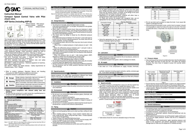
SMC Networks ASP Series User manual

SMC Networks

SMC Networks ASP Series User manual

SMC Networks SX90 Series User manual

SMC Networks

SMC Networks SX90 Series User manual

SMC Networks EX260-SEC1 User manual

SMC Networks

SMC Networks EX260-SEC1 User manual

SMC Networks VXP Series User manual

SMC Networks

SMC Networks VXP Series User manual

SMC Networks EX600-SPN4 User manual

SMC Networks

SMC Networks EX600-SPN4 User manual

SMC Networks VKF300 Series Manual

SMC Networks

SMC Networks VKF300 Series Manual

SMC Networks SJ 1000 Series User manual

SMC Networks

SMC Networks SJ 1000 Series User manual

SMC Networks XGTP31 50336 Series User manual

SMC Networks

SMC Networks XGTP31 50336 Series User manual

SMC Networks SJ2000 Series User manual

SMC Networks

SMC Networks SJ2000 Series User manual

SMC Networks VP4 Series User manual

SMC Networks

SMC Networks VP4 Series User manual

SMC Networks VO317 Series User manual

SMC Networks

SMC Networks VO317 Series User manual

SMC Networks ASP Series User manual

SMC Networks

SMC Networks ASP Series User manual

SMC Networks JSP Series User manual

SMC Networks

SMC Networks JSP Series User manual

SMC Networks VHS20 Series User manual

SMC Networks

SMC Networks VHS20 Series User manual

SMC Networks VHK-A User manual

SMC Networks

SMC Networks VHK-A User manual

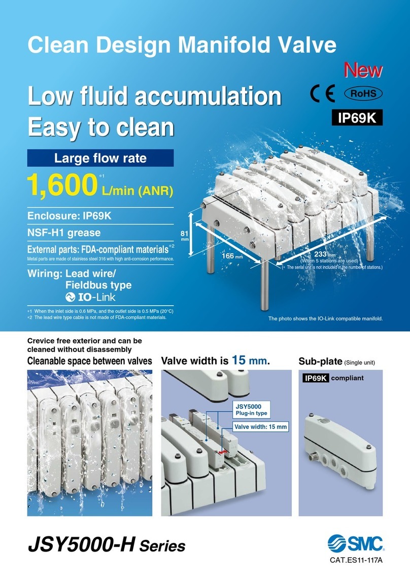
SMC Networks JSY5000-H Series User manual

SMC Networks

SMC Networks JSY5000-H Series User manual

SMC Networks DXT1215 User manual

SMC Networks

SMC Networks DXT1215 User manual

SMC Networks SV Series User manual

SMC Networks

SMC Networks SV Series User manual

SMC Networks S070 Series Manual

SMC Networks

SMC Networks S070 Series Manual

Popular Control Unit manuals by other brands

ELCA Amaltea 2 manual

ELCA

ELCA Amaltea 2 manual

Delta Tau Accessory 51E user manual

Delta Tau

Delta Tau Accessory 51E user manual

Mitsubishi Electric GOT SIMPLE GS2110-WTBD General description

Mitsubishi Electric

Mitsubishi Electric GOT SIMPLE GS2110-WTBD General description

Albalá Ingenieros, S.A. HLI3000C01 manual

Albalá Ingenieros, S.A.

Albalá Ingenieros, S.A. HLI3000C01 manual

RADEMACHER Troll Basic 5602 instruction manual

RADEMACHER

RADEMACHER Troll Basic 5602 instruction manual

Parrot FC6100 ASPEN Use manual

Parrot

Parrot FC6100 ASPEN Use manual

Infineon ASCLIN Shell UART 1 manual

Infineon

Infineon ASCLIN Shell UART 1 manual

hager JK11254D Instruction leaflet

hager

hager JK11254D Instruction leaflet

Runxin F104 A user manual

Runxin

Runxin F104 A user manual

Monacor PA-1200EX Mounting instructions

Monacor

Monacor PA-1200EX Mounting instructions

Banner MM-TA-12B instruction manual

Banner

Banner MM-TA-12B instruction manual

handtmann 12503 operating manual

handtmann

handtmann 12503 operating manual

CALEFFI 574 series manual

CALEFFI

CALEFFI 574 series manual

Sony HXCU-FB70 Service manual

Sony

Sony HXCU-FB70 Service manual

Advantech SOM-5894 user manual

Advantech

Advantech SOM-5894 user manual

CEBEK I-5 quick start guide

CEBEK

CEBEK I-5 quick start guide

ESBE ALF 4 Series manual

ESBE

ESBE ALF 4 Series manual

Siemens SINUMERIK 840D sl manual

Siemens

Siemens SINUMERIK 840D sl manual

manuals.online logo
manuals.online logoBrands
  • About & Mission
  • Contact us
  • Privacy Policy
  • Terms and Conditions

Copyright 2025 Manuals.Online. All Rights Reserved.