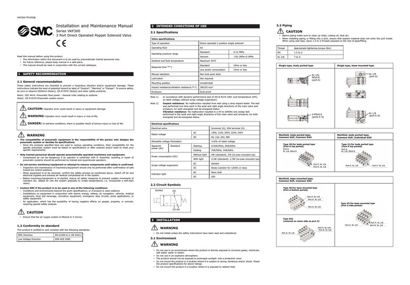
manuals.online logo
Brands
  1. Home
  2. •
  3. Brands
  4. •
  5. SMC Networks
  6. •
  7. Control Unit
  8. •
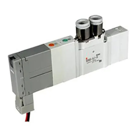
  9. SMC Networks SJ3000A User manual

SMC Networks SJ3000A User manual

Allows for the mixed mounting of 5 SJ series valve sizes
The SJ3000Aand SJ4000
have been added.
SJ4000
15
mm
SJ3000A
10
mm
SJ3000
10
mm
SJ2000
7.5
mm
SJ1000
6.5
mm
Series Valve [mm] Flow rate characteristics Flow rate∗1
Width Height C [dm3/(s·bar)] b
L/min (ANR)
SJ1000 6.5 40 0.32 0.33 83
SJ2000 7.5 40 0.36 0.13
SJ3000 10 40 0.56 0.11 128
SJ3000A 10 40 0.76 0.19 181
SJ4000 15 50 2.61 0.20 625
40
mm
50
mm
∗1 Inlet pressure: 0.6 MPa, Outlet pressure: 0.5 MPa (at 20°C)
Connector
connection
CAT.ES11-87E
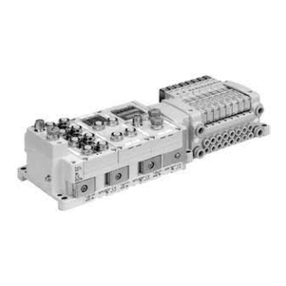
4-Port Solenoid Valve
Cassette Type Manifold
Rubber Seal
SJ1000/2000/3000/4000
Series
∗1
SJ2000/3000 only
∗1
Power consumption
0.15 W*1(SJ3000/4000 with power-saving circuit)
0.23 W*1(SJ1000/2000 with power-saving circuit)
*1 Refer to page 140 for details.
The manifold uses
halogen-free lead wires.
Connector type (Card edge type)
SJ1000, SJ2000, SJ3000, and
SJ4000 series valves can be
mounted together.
· Easily increase or decrease the
number of stations and easily
replace valves
·
The 34-pin connector allows for up
to 16 stations with double solenoids
or 32 stations with single solenoids.
Non plug-in individual wiring
compliant
*SJ2000/3000 only
4-Port Solenoid Valve Cassette Type Manifold SJ1000/2000/3000/4000 Series
Card edge
connector
2.61
0.32
0.76
0.56
0.36
106.5 7.5 15
*1 Flow rate Q is the reference value when the inlet
side is 0.6 MPa and the outlet side is 0.5 MPa
(20°C)
*2 Weight reduced by changing the valve body material
from zinc to aluminum
*Weight (g) for the 5-station D sub-connector manifold/
single solenoids
Valve width [mm]
Sonic conductance C [dm3/(s·bar)]
SJ1000/2000/3000/4000
SJ2000
SJ1000
SJ4000
SJ3000A
456 g
(−12%)
SJ3000 comparison
413 g
(−20%)
SJ3000 comparison
386 g
(−25%)
SJ3000 comparison
796 g
SJ3000
Flow rate
4.9 times
Flow rate Q
(Reference value)*1
128 a625
L/min (ANR)
SJ3000 comparison
Flow rate
1.4 times
Flow rate Q
(Reference value)*1
128 a181
L/min (ANR)
SJ3000 comparison
516 g
*2
1
4-position dual 3-port valve
• 3-port valves integrated into a single valve
• It is possible to control the 4(A) and 2(B)
ports individually.
• Can be mounted on the same manifold as
a 4-port valve
• 3 types of combinations are available.
4-Port Solenoid Valve Cassette Type Manifold SJ1000/2000/3000/4000 Series
Unlocked
Locked
Type of manual overrideLight indication
Piping variations
With One-touch fittings Threaded type
The threaded type is
not available for the
1(P) or 3/5(E) ports.
Manual locking
A sliding mechanism covers the manual override button to
prevent unintentional operation.
Connector mounting
direction
Connecter mounting direction can
be changed by sliding the switch.
Fittings are replaceable.
Fittings (including type and size) can be easily
changed by removing a clip.
Valve connection
mechanism
Connection between valves can be
secured using the valve lock switch.
Connection can be confirmed by
checking to see whether the
connection hook is inserted into the
connection groove of the adjacent
valve.
*Excludes the SJ4000
SOL.a
SOL.a: ON
SOL.b: ON
SOL.b
The valve coil is kept in a de-energized
state even when there is an electric
signal from the manifold side
connector, and this enables manifold
operation.
With switch (Connector type)
• It is possible to shut off the signal of each valve individually.
• Manual operation is possible by switching the valve OFF, even if it is
in an energized state.
*SJ2000/3000 only
Green
ON
OFF Switch
Clip
Non-locking
push type
Slide locking
type
Push-turn
locking
slotted type
The manual
button will hold the
pushed (ON) status.
OFF
ON
B side manual
(Yellow)
A side manual
(Blue)
FREE
LOCK
Switch
Valve lock switch
Connection hook
The word “FREE” can be seen
when connection is unlocked.
SJ1000 SJ2000 SJ3000 SJ4000
Elbow fitting — V V —
Thread piping — V V —
SJ1000 SJ2000 SJ3000 SJ4000
Non-locking push type V V V V
Push-turn locking
slotted type V V V V
Slide locking type — V V —
Red
A side coil
B side coil
B side manual
A side manual
B side passage symbol
A side passage symbol
A side B side Symbol
N.C.
valve
N.C.
valve
N.O.
valve
N.O.
valve
N.C.
valve
N.O.
valve
1(P)5(EA)
4(A)
3(EB)
2(B)
1(P)5(EA)
4(A)
3(EB)
2(B)
1(P)5(EA)
4(A)
3(EB)
2(B)
Details Ap. 142
2
¡CC-Link (32 outputs), DeviceNet®(16 or 32 outputs)
¡The connector allows for easy attaching/detaching of the SI
unit and wiring.
Separated valve power unit and transmission power unit/Improved
maintenance safety
Select between a T-branch or a straight type communication connector
¡Max. 128 points (Input 64 points/Output 64 points)
¡All wires can be plugged into the connector units.
¡CC-Link, DeviceNet®, and PROFIBUS-DP compliant
SI unit
Communication connector
Transmission power unit (for CC-Link)
Valve power unit
Straight type
T-branch type
For DeviceNet®, a transmission power unit exists in the
communication connector side of the T-branch or straight type.
Connector Type Manifold
Cable
4-Port Solenoid Valve Cassette Type Manifold SJ1000/2000/3000/4000 Series
D-sub connector
EX510 Gateway type serial transmission
system
*Connector type only
*Excludes the SJ4000
Flat ribbon cable
EX180 Integrated type (for output) serial
transmission system
*Connector type only
Plug-in Cable Type Manifold
*SJ2000/3000 only
3
D side
U side
FREE
LOCK
P port
0.5 MPa
D side
Regulator
block
0.2 MPa
U side
This is a regulator block with the same width (10 mm) as the SJ3000.
Pressure supplied from the D side is used to reduce pressure in the manifold.
The U side valves are all depressurized by the regulator block.
*Excludes the SJ4000
Regulator block
SJ3000-01-P(-H)
SJ3000-M1-P(-H)
SJ3000-00-P(-H)
Both the pressure gauge mounting position and the method of operating the pressure adjustment
screw can be selected.
*This reduces supply pressure from the
D side of the manifold. Supply pressure
from the U side cannot be reduced.
Pneumatic circuit (Example of a regulator block installation)
1(P) 3/5(E)
(Pilot passage)
2(B)4(A)
(SJ3260)
2(B)4(A)
(SJ2260) (SJ3000-00-P) (SJ3260) (SJ2260)
2(B)4(A) 2(B)4(A)
0.5 MPa
U sideD side
Regulator block
Set to 0.2 MPa
P port
0.5 MPa applied
0.2 MPa
With manual operation of the
pressure adjustment screw
Pressure gauge, top mounting
Pressure gauge, side mounting
Without pressure gauge
4-Port Solenoid Valve Cassette Type Manifold SJ1000/2000/3000/4000 Series
Regulator block
Details Ep. 109
4
FREE
LOCK
Intermediate
connector block
U side
D side
This connector block can be used by inserting it into the middle
of the manifold.
It can be used, for example, when you wish to separate
electrical control of valves in the same manifold or when
the number of control points is insufficient.
Intermediate connector block
Intermediate connector block wiring example
∗The U side solenoid valve with an intermediate connector block can be controlled.
∗The intermediate connector block can be ordered using the manifold specification sheet.
Intermediate connector block
D side
U side
U side
D side
SOL.b
SOL.a
SOL.a
SOL.b
Station 2
Station 1
12
3
5
7
4
6
8
19 20
COM
Connector block
Double solenoid
(Station 1)
SOL.a SOL.b
Double solenoid
(Station 2)
SOL.bSOL.a
SOL.b
SOL.a
SOL.a
SOL.b
Station 4
Station 3
12
3
5
7
4
6
8
19 20
COM
SOL.a SOL.b
Double solenoid
(Station 3)
SOL.bSOL.a
Double solenoid
(Station 4)
Intermediate
connector block
4-Port Solenoid Valve Cassette Type Manifold SJ1000/2000/3000/4000 Series
Details Ep. 115
5
This pressure regulator is intended to adjust the SUP pressure of the manifold.
Additionally, a pressure switch and pressure gauge can be mounted on it.
*Excludes the SJ4000
SUP/EXH block with regulator and pressure switch
Lateral knob
Upward knob
Valve with speed controller
SUP/EXH block with regulator and pressure switch
Pneumatic circuit (Installation example of a SUP/EXH block with regulator and pressure switch and a valve with
speed controller)
As a speed controller is built into this valve, the cylinder
speed can be adjusted on the valve side.
2 types, meter-in and meter-out, are provided.
Meter-in: Black
Meter-out: Silver
(SJ3000B-PCB)
(B)2 4(A)
(SJ3260-S0)
(SJ3260)
4(A)(B)2
(SJ3260)
4(A)(B)2
(SJ3260-S1)
(SJ3260)
(E)3/5
(Pilot passage)
4(A)(B)2 4(A)(B)2
1(P)
U sideD side
Valve with speed controller SUP/EXH block with regulator and pressure switch
4-Port Solenoid Valve Cassette Type Manifold SJ1000/2000/3000/4000 Series
Details Ep. 111
Details Ep. 111
6
Low-profile
SUP/EXH block
10.2
85
123
The width dimension of the SUP/EXH block is only 10.2 mm, smaller
than the 15.5 mm width of the standard product, which allows for the
length of the entire manifold to be reduced.
∗Excludes the SJ4000
Low-profile SUP/EXH block
(Made to order)
∗SJ1000 5-station manifold example
4-Port Solenoid Valve Cassette Type Manifold SJ1000/2000/3000/4000 Series
[mm]
Width Reduction
Low-profile SUP/EXH block 10.2 5.3
Standard product 15.5 —
10.2
mm
∗
The values are for an individually operated 2-position type manifold base with 5 stations.
∗Excludes the SJ3000A (Large flow type) and SJ4000
Flow Rate Characteristics
Series
Port size Flow rate characteristics
1(P)
3/5(E)
4, 2
(A, B)
1 R4/2 (P RA/B) 4/2 R3/5 (A/B RE)
C [dm3/(s·bar)] C [dm3/(s·bar)]
SJ1000 C6 C2 0.12 0.13
C4 0.26 0.30
SJ2000 C6
C2 0.13 0.13
C4 0.30 0.34
M3 0.18 0.20
SJ3000 C6
C2 0.13 0.14
C4 0.38 0.45
C6 0.45 0.51
M5 0.40 0.45
Part no. Applicable
port
TG-0204 TG-0608 TG-1012
Applicable tubing O.D.
ø2/ø4 ø6/ø8 ø10
Series
SJ1000 For A, B port V— —
For P, E port — V—
SJ2000 For A, B port V— —
For P, E port — V—
SJ3000 For A, B port V V —
For P, E port — V—
SJ4000 For A, B port — V—
For P, E port — V V
ø6 One-touch fitting
Tube Releasing Tool Details EWeb Catalog
Use this to remove tubing from the A, B and P, E ports.
Details Ep. 117
TG-0204 TG-0608 TG-1012
ø8 ø12
ø6 ø10
ø4
ø2
7
1(P)
Release pressure port
3/5(E)
Vacuum pressure port
Slotted
locking typeManual
2(B)
Vacuum pad port
PS port: Pressure detection port
(M5 x 0.8)
Plug-in
Connector connection
Cable connection
• Individual wiring
Non plug-in
Adsorbing and Transferring System Circuit Example
With 2 built-in spool valves
Vacuum suction and release can be
controlled with a single valve.
• Serial (EX180)
• Serial (EX510)
<Connector connection>
• D-sub connector
• Flat ribbon cable
<Cable connection>
• D-sub connector
• Flat ribbon cable
Wiring variations
Filter
Restrictor
• Eliminates foreign matter on the
vacuum and release sides
• Replaceable
• Flow rate adjustment
of release air
• Prevents workpiece
blow-off
LPower consumption: 0.15 W*1(with power-
saving circuit)
LWidth: 10 mm (same as the SJ3000 series)
LEquipped with restrictor to enable flow rate
adjustment of release air
LReplaceable filters are built-in on the vacuum
and release sides.
LEquipped with a pressure detection port
which allows for the connection of a
pressure switch, etc.
LCan be combined with 4-port solenoid
valves, as well as SJ1000, 2000, and 3000
series valves (Special order)
(Please contact SMC for details.)
LEnables 2-system pressure switching where
the 1(P) port and the 3/5(E) port are set to
different positive pressures
(In this case, flow can be adjusted on the P-port side only.)
*1 Refer to page 140 for details.
2(B)
Vacuum pad port
X
1(P)
Release
pressure port
3/5(E)
Vacuum
pressure port
Vacuum
pressure
switching
valve
Filter
Vacuum side
Filter
Release side
SJ3A6
Release pressure
switching valve
(Built-in restrictor)
Vacuum Release Valve with Restrictor
SJ3A6 Series
4-Port Solenoid Valve Cassette Type Manifold SJ1000/2000/3000/4000 Series
8
Individual wiring
EX510
(Gateway type)
EX180
(For output)
Flat ribbon cable
D-sub connector
Connection
Parallel wiring
Serial transmission
SJ1000/2000/
3000/4000
SS5J1/2/3/4-60
SJ2000/3000
SS5J2/3-60L
SJ2000/3000
SS5J2/3-60-
SJ3A6
SS3J3-V60
SJ3A6
SS3J3-V60L
SJ3A6
SS3J3-V60-
4-port solenoid valve
Vacuum release valve with restrictor
Plug-in
Non plug-in
Connector type
Cable type
Plug-in
Non plug-in
Connector type
Cable type
∗1 A linkage-printed circuit board is built into individual wiring
valves so as to allow for use in combination with the plug-in types.
∗2
Specify the required specifications on the manifold specification sheet.
∗3 All single wiring or all double wiring can be specified.
∗4 The vacuum release valve can only use double wiring.
∗5 Only the SJ3000 size is available.
∗6
Adding 1 additional station is possible up to the max. number of stations.
∗7 Only the SJ2000 and SJ3000 sizes are available.
∗8 Excludes the SJ4000
p. 30
p. 62
p. 78
p. 29 p. 29 p. 61 p. 77
p. 33 p. 33
p. 95
p. 128p. 127 p. 127 p. 127 p. 127
p. 129 p. 129
p. 133
∗1
∗7
∗8∗8
∗1
—
——
————
—
——
————
Manifold Variations
4-Port Solenoid Valve
SJ1000/2000/3000 /4000 Series
Vacuum Release Valve
with Restrictor
SJ3A6 Series
Manifold type
Item
9
Manifold options Solenoid valve specifications
Mixed wiring
Single/Double
Mixed type M60
SJ1000/2000/3000/4000
Increase of
manifold stations
Voltage suppressor
Non-polar
+/– common
Polar
With power-saving circuit
With individual switch
Main valve fluororubber
specification
Blanking block
Block disk/
Different-pressure pneumatic
circuit diagram
—
—
—
— —
—
—
—
SUP/EXH block with
regulator and pressure switch
—
—
Regulator block
—
—
Valve with speed controller
Dual flow fitting
p. 108
p. 108
p. 108
p. 109
p. 109
p. 111
p. 111
p. 111
p. 111 p. 91
p. 111 p. 90
p. 115 p. 90
p. 115 p. 90
p. 91
p. 90
p. 116
p. 116
p. 116
p. 116
p. 116
p. 116
p. 105p. 103p. 29
p. 31
p. 105p. 103
p. 105p. 103p. 95
p. 105p. 103
p. 105p. 103
p. 105
Low-profile SUP/EXH block
p. 117
p. 117
p. 117
p. 117
p. 117
p. 117p. 103
— — —
—
— — —
—
—
— —
—
Intermediate
connector block
—
—
—
— — ——
—
—
SJ1000/2000/3000/4000 Series
SJ3A6 Series
—
—
—
∗2∗5∗8∗8∗8∗8
∗5
∗5
∗5
∗6
∗6
∗5
∗5
∗3
∗4
∗4
∗4
∗7
∗7
∗7∗7
10
Common Specifications ����������������������������������������������������� p. 13
Construction������������������������������������������������������������� p. 18
D-sub Connector/Flat Ribbon Cable
How to Order: Connector Type ������������������������� p. 29
How to Order: Cable Type ���������������������������� p. 33
Manifold Electrical Wiring: Connector Type, Cable Type ��������� p. 35
Dimensions: Connector Type, Cable Type ������������������ p. 37
EX180 Integrated Type (For Output) Serial Transmission System
How to Order: Connector Type ������������������������� p. 61
Dimensions: Connector Type �������������������������� p. 65
EX510 Gateway Type Serial Transmission System
How to Order: Connector Type ������������������������� p. 77
Dimensions: Connector Type �������������������������� p. 79
Manifold Exploded View: Connector Type, Cable Type �������� p. 86
Manifold Exploded View (Mixed Specification): Connector Type �� p. 89
How to Increase Manifold Stations: Connector Type, Cable Type
��� p. 90
Individual Wiring
How to Order ������������������������������������ p. 95
Dimensions ������������������������������������� p. 97
Manifold Exploded View: Individual Wiring ��������������� p. 102
Manifold Options ��������������������������������������������������������� p. 103
Made to Order ����������������������������������������������������������� p. 116
Manifold Variations ��������������������������������������������������������� p. 9
CONTENTS
4-Port Solenoid Valve SJ1000/2000/3000/4000 Series
Plug-in Connector Type Manifold/Cable Type Manifold
Non Plug-in Individual Wiring Manifold
p. 28
p. 94
11
Manifold Exploded View: Connector Type, Cable Type, Individual Wiring �������������������� p. 136
Specific Product Precautions������������������������������������������������� p. 138
Common Specifications ���������������������������������������������������� p. 125
Construction/Circuit Example ������������������������������������������������ p. 126
D-sub Connector/Flat Ribbon Cable/Serial Wiring (EX180/EX510)
How to Order: Connector Type ������������������������ p. 127
How to Order: Cable Type ��������������������������� p. 129
Dimensions: Connector Type, Cable Type ����������������� p. 131
Individual Wiring
How to Order ����������������������������������� p. 133
Dimensions ������������������������������������ p. 135
Vacuum Release Valve with Restrictor SJ3A6 Series
Plug-in Connector Type Manifold/Cable Type Manifold
Non Plug-in Individual Wiring Manifold
p. 124
12
SJ
1000
2000
3000
4000
Common
Specifications
SJ3A6
Plug-in
EX180EX510
Construction
D-sub
Flat Ribbon
Individual
Wiring
Individual
Wiring
Specific Product
Precautions
Manifold
Options
Made to
Order
Common Spec.
Construction
D-sub
Flat Ribbon
Serial
Non
Plug-in
Non
Plug-in Plug-in
Manifold Specifications
4-Port Solenoid Valve
SJ1000/2000/3000/4000 Series
Common Specifications
∗1 The SJ1000/4000 series does not support cable connection or individual wiring.
∗2 The weight W is the value for the D-sub connector manifold with internal pilot and SUP/EXH block straight fittings specifications only. To obtain the
weight with solenoid valves mounted, add the solenoid valve weights given on page 16 for the appropriate number of stations. Refer to page 106 for the
weight of the DIN rail. (Please contact SMC for the weight of the external pilot specification with elbow fittings.)
∗3 Refer to page 117 for low-profile SUP/EXH block specifications.
∗4 Not available for the SJ4000 series
∗5 Inch size elbow fittings are not available.
∗6 Metric/Inch size elbow fittings are not available.
∗When many valves are operated simultaneously, use the B type (SUP/EXH both sides), supplying pressure to the 1(P) ports on both sides and exhaust-
ing from the 3/5(E) ports on both sides.
Model∗1
D-sub connector Flat ribbon cable Serial wiring Individual wiring
Type 60F
Connector type/
Cable type
Type 60P
Connector type/
Cable type
Type 60PG
Connector type/
Cable type
Type 60PH
Connector type/
Cable type
Type 60Sl
EX180/
Connector type
Type 60S6B∗4
EX510/
Connector type
Type 60∗4
Manifold type Plug-in, Connector type/Cable type Plug-in, Connector type Non plug-in
1(P: SUP), 3/5(E: EXH) Common SUP, EXH
Valve stations Connector type: 1 to 24 stations
Cable type: 2 to 20 stations
1 to 18 stations
(Type PG) 1 to 8 stations 1 to 32 stations 1 to 16 stations 1 to 20 stations
Applicable connector
D-sub connector
Compliant with
MIL-C-24308
JIS-X-5101
Flat ribbon cable connector
Socket: 26 pins MIL type
with strain relief
Compliant with MIL-C-83503
Flat ribbon cable connector
Socket: 20 pins MIL type
with strain relief
Compliant with MIL-C-83503
Flat ribbon cable connector
Socket: 10 pins MIL type
with strain relief
Compliant with MIL- C-83503
— — —
Internal
wiring
SJ1000 Connector type: positive common, negative common —
SJ2000/3000(A)
Connector type: non-polar, positive common, negative common/Cable type: positive common, negative common
—
SJ4000 Connector type: non-polar, positive common, negative common — —
4(A), 2(B) port
piping specification
Location Valve
Direction
Horizontal, Upward, Downward (Elbow fittings are used for upward or downward. Upward and downward are not available for the SJ1000/4000.)
Port
size
1(P),
3/5(E)
port
SJ1000/
2000/
3000(A)
C6, C8, N7, N9∗5
SJ4000 C10∗6
4(A),
2(B) port
SJ1000 C2, C4
SJ2000 C2, C4, N1, N3, M3
SJ3000 C2, C4, C6, N1, N3, N7, M5
SJ3000A C4, C6
SJ4000 C6, C8
Weight W [g]∗2
n: Number of SUP/EXH blocks
m: Weight of DIN rail
SJ1000/
2000/
3000(A)
Standard: W = 51n + m + 133
Low-profile SUP/EXH block specification: W = 32n + m + 133∗3
SJ4000 Manifold [D-sub connector]: W = 81n + m + 144
13
Common Specifications SJ1000/2000/3000/4000 Series
∗The values are for an individually operated 2-position type manifold base with 5 stations.
Please contact SMC for details on 4-position dual 3-port valves.
SJ3000A Series
Port size Flow rate characteristics
1(P)
3/5(E)
4, 2
(A, B)
1 R4/2 (P RA/B) 4/2 R3/5 (A/B RE)
C [dm3/(s·bar)] b Cv C [dm3/(s·bar)] b Cv
C8
C4 0.53 0.34 0.17 0.75 0.21 0.20
C6 0.68 0.27 0.19 0.76 0.19 0.21
M5 0.55 0.33 0.16 0.75 0.21 0.20
SJ4000 Series
Port size Flow rate characteristics
1(P)
3/5(E)
4, 2
(A, B)
1 R4/2 (P RA/B) 4/2 R3/5 (A/B RE)
C [dm3/(s·bar)] b Cv C [dm3/(s·bar)] b Cv
C10 C6 1.47 0.36 0.43 2.34 0.34 0.70
C8 2.14 0.24 0.58 2.61 0.20 0.68
Flow Rate Characteristics
SJ1000 Series
SJ3000 Series
Port size Flow rate characteristics
1(P)
3/5(E)
4, 2
(A, B)
1 R4/2 (P RA/B) 4/2 R3/5 (A/B RE)
C [dm3/(s·bar)] b Cv C [dm3/(s·bar)] b Cv
C8
C2 0.13 0.56 0.04 0.14 0.51 0.04
C4 0.42 0.17 0.11 0.45 0.16 0.11
C6 0.55 0.10 0.12 0.56 0.11 0.12
M5 0.40 0.28 0.11 0.45 0.15 0.11
SJ2000 Series
Port size Flow rate characteristics
1(P)
3/5(E)
4, 2
(A, B)
1 R4/2 (P RA/B) 4/2 R3/5 (A/B RE)
C [dm3/(s·bar)] b Cv C [dm3/(s·bar)] b Cv
C8
C2 0.13 0.55 0.04 0.13 0.50 0.04
C4 0.33 0.16 0.08 0.36 0.13 0.08
M3 0.18 0.52 0.06 0.20 0.29 0.06
Port size Flow rate characteristics
1(P)
3/5(E)
4, 2
(A, B)
1 R4/2 (P RA/B) 4/2 R3/5 (A/B RE)
C [dm3/(s·bar)] b Cv C [dm3/(s·bar)] b Cv
C8 C2 0.12 0.64 0.04 0.13 0.59 0.04
C4 0.28 0.35 0.08 0.32 0.33 0.08
14
SJ
1000
2000
3000
4000
Common
Specifications
SJ3A6
Plug-in
EX180EX510
Construction
D-sub
Flat Ribbon
Individual
Wiring
Individual
Wiring
Specific Product
Precautions
Manifold
Options
Made to
Order
Common Spec.
Construction
D-sub
Flat Ribbon
Serial
Non
Plug-in
Non
Plug-in Plug-in
SJ1000/2000/3000/4000 Series
D-sub connector
Flat ribbon cable
EX180 Integrated type (for output)
serial transmission system
EX510 Gateway type
serial transmission system
Individual wiring
Solenoid Valve Specifications
∗Impact resistance : No malfunction occurred when it is tested with a drop tester in the axial direction and at the
right angles to the main valve and armature in both energized and de-energized states every
once for each condition. (Value in the initial state)
Vibration resistance: No malfunction occurred in one sweep test between 45 and 2000 Hz in the axial direction
and at the right angles to the main valve and armature in both energized and de-energized
states for each condition. (Value in the initial state)
∗Based on dynamic performance test, JIS B 8419:2010 (Coil temperature: 20°C, at rated voltage)
Response Time
Solenoid Specifications
∗1 For the allowable voltage fluctuation for Z and T types (with power-saving circuit), please observe the follow-
ing range because they have voltage drop due to internal circuit.
Z type 24 VDC: –7% to +10%
12 VDC: –4% to +10%
T type 24 VDC: –5% to +10%
12 VDC: –6% to +10%
∗2 Refer to page 140 for details.
∗3 SJ1000 series available as power-saving type only. Standard type (without power-saving circuit) cannot be
selected.
∗4 The 12 VDC specification is not available for the SJ4000.
Coil rated voltage 24 VDC, 12 VDC∗4
Allowable voltage fluctuation ±10% of rated voltage∗1
Power
consumption
[W]
Standard SJ2000 0.55
SJ3000/4000 0.4
With power-
saving circuit∗3
(Continuous duty type)
SJ1000/2000 0.23∗2
[
Starting 0.55, Holding 0.23
]
SJ3000/4000 0.15∗2
[
Starting 0.4, Holding 0.15
]
Surge voltage suppressor Diode
Indicator light LED
Fluid Air
Internal pilot
operating pressure
range [MPa]
2-position single 0.15 to 0.7
4-position dual 3-port valve
2-position double 0.1 to 0.7
3-position 0.2 to 0.7
External pilot
operating pressure
range [MPa]
Operating pressure range
–100 kPa to 0.7
Pilot
pressure
range
2-position single
0.25 to 0.7
2-position double
3-position
Ambient and fluid temperatures [°C] –10 to 50 (No freezing)
Max. operating
frequency [Hz]
2-position single, double
10 (SJ4000: 5 Hz)
4-position dual 3-port valve
3-position 3
Manual override (Manual operation) Non-locking push type
Push-turn locking slotted type
Pilot exhaust method
Internal pilot Main and pilot valve common exhaust
External pilot Pilot valve individual exhaust
Lubrication Not required
Mounting orientation Unrestricted
Impact/Vibration resistance [m/s2]150/30
Enclosure Dustproof
Type of actuation Response time [ms] (at 0.5 MPa)
SJ1000 SJ2000 SJ3000 SJ4000
2-position single 16 16 16 26
2-position double 10 10 10 12
3-position 20 34 22 29
4-position dual 3-port valve 18 30 30 30
15
Common Specifications SJ1000/2000/3000/4000 Series
Valve model Type of actuation Port size Weight
[g]
4(A), 2(B)
SJ4m60-C6
2-position
Single
C6
ø6 One-
touch fitting
111
Double 121
3-position
Closed center
131Exhaust center
Pressure center
4-position
Dual 3-port valve 120
SJ4m60-C8
2-position
Single
C8
ø8 One-
touch fitting
108
Double 118
3-position
Closed center
128Exhaust center
Pressure center
4-position
Dual 3-port valve 117
Weight
∗Please contact SMC for the weight of elbow fittings.
Model: SJ3000 Series
∗Please contact SMC for the weight of elbow fittings.
Model: SJ1000/2000 Series
Valve model Type of actuation Port size Weight
[g]
4(A), 2(B)
SJ1m60T-C2
2-position
Single
C2
ø2 One-
touch fitting
34
Double 38
3-position
Closed center
41Exhaust center
Pressure center
4-position
Dual 3-port valve 38
SJ1m60T-C4
2-position
Single
C4
ø4 One-
touch fitting
36
Double 40
3-position
Closed center
43Exhaust center
Pressure center
4-position
Dual 3-port valve 40
SJ2m60-C2
2-position
Single
C2
ø2 One-
touch fitting
43
Double 46
3-position
Closed center
50Exhaust center
Pressure center
4-position
Dual 3-port valve 46
SJ2m60-C4
2-position
Single
C4
ø4 One-
touch fitting
41
Double 44
3-position
Closed center
48Exhaust center
Pressure center
4-position
Dual 3-port valve 44
SJ2m60-M3
2-position
Single
M3 x 0.5
39
Double 42
3-position
Closed center
46Exhaust center
Pressure center
4-position
Dual 3-port valve 42
Valve model Type of actuation Port size Weight
[g]
4(A), 2(B)
SJ3m60-C2
2-position
Single
C2
ø2 One-
touch fitting
63
Double 71
3-position
Closed center
75Exhaust center
Pressure center
4-position
Dual 3-port valve 71
SJ3m60-C4
2-position
Single
C4
ø4 One-
touch fitting
65
Double 73
3-position
Closed center
77Exhaust center
Pressure center
4-position
Dual 3-port valve 73
SJ3m60-C6
2-position
Single
C6
ø6 One-
touch fitting
61
Double 69
3-position
Closed center
73Exhaust center
Pressure center
4-position
Dual 3-port valve 69
SJ3m60-M5
2-position
Single
M5 x 0.8
57
Double 65
3-position
Closed center
69Exhaust center
Pressure center
4-position
Dual 3-port valve 65
SJ3m60A-C4
2-position
Single C4
ø4 One-
touch fitting
53
Double 64
SJ3m60A-C6
Single C6
ø6 One-
touch fitting
49
Double 60
SJ3m60A-M5
Single
M5×0.8
46
Double 57
( ) ( )
( )
( )
( )
( )
( )
( )
( )
( )
( )
Model: SJ4000 Series
16
SJ
1000
2000
3000
4000
Common
Specifications
SJ3A6
Plug-in
EX180EX510
Construction
D-sub
Flat Ribbon
Individual
Wiring
Individual
Wiring
Specific Product
Precautions
Manifold
Options
Made to
Order
Common Spec.
Construction
D-sub
Flat Ribbon
Serial
Non
Plug-in
Non
Plug-in Plug-in
SJ1000/2000/3000/4000 Series
Connector Wiring Diagram
For both serial and parallel wiring, additional valves are sequentially assigned pins on the connector.
This makes it completely unnecessary to disassemble the connector unit.
LMounting a valve with individual wiring
LSingle solenoid with double wiring
LSingle solenoid and double solenoid
Station 3
Station 2
Station 1
···
Double solenoid
Station 3
Single solenoid
Station 2
Double solenoid
Station 1
Connector side
(D-sub connector, etc.)
SOL.b
SOL.a
SOL.a
SOL.b
SOL.a
Common (+, –)
Solenoid
SOL.b
SOL.a
Station 3
SOL.a
Unused terminal
Station 2
SOL.a
SOL.b
Station 1
Double solenoid
Station 3
···
Common (+, –)
Single solenoid
(Double wiring)
Station 2
Double solenoid
Station 1
Connector side
(D-sub connector, etc.)
Solenoid
Station 3
SOL.a
SOL.b
SOL.a
SOL.b
SOL.a
Station 4
Station 1
···
BA
Common (+)
Individual wiring (M type)
Station 2
Single solenoid
Station 4
Double solenoid
Station 3
Double solenoid
Station 1
Connector side
(D-sub connector, etc.)
Common (+, –)
Solenoid
17
SJ1000/2000: Connector Type
Symbol
2-position single 2-position single with back
pressure check valve
2-position double with back
pressure check valve
2-position single
2-position double 2-position double
3-position closed center
3-position closed center/exhaust center/pressure center
SJ1260KT/SJ2260K
[With back pressure check valve]
Replacement Parts
Component Parts
3-position exhaust center
SJ1000/2000/3000/4000 Series
Construction
3-position pressure center
1(P)5(EA)/3(EB)
2(B
)
4(A
)
!0u!1qywerto
i
1(P)
4(A
)
2(B
)
5(EA)/3(EB)
!0u!1qywerto
i
1(P)5(EA)/3(EB)
4(A
)
2(B
)
!0u!1qywerto
i
1(P)5(EA)/3(EB)
2(B
)
4(A
)
!0u!1qywerto
i
(EA)5 1
(P)
3(EB
)
2(B)(A)4
(EA)5 1
(P)
3(EB
)
2(B)(A)4
(EA)5 1
(P)
3(EB)
2(B)(A)4
(EA)5 1
(P)
3(EB)
2(B)(A)4
(EA)5 1
(P)
3(EB)
2(B)(A)4
(EA)5 1
(P)
3(EB)
2(B)(A)4
(EA)5 1
(P)
3(EB)
2(B)(A)4
No. Description Material Note
1 Spool valve assembly
Resin/HNBR
3-position solenoid valve:
Aluminum/HNBR
—
2 Body Zinc die-cast —
3 Adapter plate Resin White
4 Pilot adapter Resin White
5 Pilot valve assembly — —
6 Body cover Resin White
7 Port block Resin White
8 Bottom cover Resin White
9 Light cover Resin Light blue
No. Description Part no.
10 One-touch fitting Refer to the One-touch fitting part no.
on page 142.
11 Clip SJ1000 SJ1000-CL-1 (10 pcs.)
SJ2000 SJ2000-CL-1 (10 pcs.)
18
SJ
1000
2000
3000
4000
Common
Specifications
SJ3A6
Plug-in
EX180EX510
Construction
D-sub
Flat Ribbon
Individual
Wiring
Individual
Wiring
Specific Product
Precautions
Manifold
Options
Made to
Order
Common Spec.
Construction
D-sub
Flat Ribbon
Serial
Non
Plug-in
Non
Plug-in Plug-in
SJ1000/2000/3000/4000 Series
SJ1B60T/SJ2B60
[
N.O. valve x 2]
SJ1B60KT/SJ2B60K
with back pressure check valve
SJ1C60T/SJ2C60
[N.C., N.O. valve x 1 (each)]
SJ1C60KT/SJ2C60K
with back pressure check valve
4-position dual 3-port valve
SJ1A60T/SJ2A60
[
N.C. valve x 2]
Symbol
SJ1A60KT/SJ2A60K
with back pressure check valve
SJ1A60T/SJ2A60 [N.C. valve x 2]
SJ1B60T/SJ2B60 [N.O. valve x 2]
SJ1C60T/SJ2C60
[N.C., N.O. valve x 1 (each)]
1(P)5(EA)/3(EB)
1(P)5(EA)/3(EB)
1(P)5(EA)/3(EB)
SJ1A60KT/SJ2A60K
[With back pressure check valve]
1(P)5(EA)/3(EB)
2(B)
4(A)
2(B)
4(A)
2(B)
4(A)
2(B)
4(A)
!1i!2querty!0
o
q
!1i!2wuerty!0
o
w
!1i!2wuerty!0
o
q
!1i!2querty!0
o
q
1(P)5(EA)
4(A)
3(EB)
2(B)
1(P)5(EA)
4(A)
3(EB)
2(B)
1(P)5(EA)
4(A)
3(EB)
2(B)
1(P)5(EA)
4(A)
3(EB)
2(B)
1(P)5(EA)
4(A)
3(EB)
2(B)
1(P)5(EA)
4(A)
3(EB)
2(B)
Replacement Parts
SJ1000/2000: Connector Type
No. Description Part no.
11 One-touch fitting Refer to the One-touch fitting part no.
on page 142.
12 Clip SJ1000 SJ1000-CL-1 (10 pcs.)
SJ2000 SJ2000-CL-1 (10 pcs.)
Component Parts
No. Description Material Note
1
Spool valve assembly
Resin/HNBR
N.C. (Normally closed)
2
Spool valve assembly
Resin/HNBR
N.O. (Normally open)
3 Body Zinc die-cast
—
4 Adapter plate Resin
White
5 Pilot adapter Resin
White
6
Pilot valve assembly
—
—
7 Body cover Resin
White
8 Port block Resin
White
9 Bottom cover Resin
White
10 Light cover Resin
Light blue
19

This manual suits for next models

18

Other SMC Networks Control Unit manuals
SMC Networks VDW30-XF Series Owner's manual

SMC Networks

SMC Networks VDW30-XF Series Owner's manual

SMC Networks EX260 Series User manual

SMC Networks

SMC Networks EX260 Series User manual

SMC Networks VHS20 Series User manual

SMC Networks

SMC Networks VHS20 Series User manual

SMC Networks SY3000 SERIES Installation manual

SMC Networks

SMC Networks SY3000 SERIES Installation manual

SMC Networks VP500 Series User manual

SMC Networks

SMC Networks VP500 Series User manual

SMC Networks VF1000 Series User manual

SMC Networks

SMC Networks VF1000 Series User manual

SMC Networks VM1000 Series User manual
SMC Networks

SMC Networks VM1000 Series User manual
SMC Networks SX90 Series User manual

SMC Networks

SMC Networks SX90 Series User manual

SMC Networks VND Series User manual

SMC Networks

SMC Networks VND Series User manual

SMC Networks VT325 Series User manual

SMC Networks

SMC Networks VT325 Series User manual

SMC Networks EX600 Series User manual

SMC Networks

SMC Networks EX600 Series User manual

SMC Networks JSXF Series User manual

SMC Networks

SMC Networks JSXF Series User manual

SMC Networks VP4 Series User manual

SMC Networks

SMC Networks VP4 Series User manual

SMC Networks LLB1 Series User manual

SMC Networks

SMC Networks LLB1 Series User manual

SMC Networks AKP Series User manual

SMC Networks

SMC Networks AKP Series User manual

SMC Networks VCC Series User manual

SMC Networks

SMC Networks VCC Series User manual

SMC Networks VQZ100 Series User manual

SMC Networks

SMC Networks VQZ100 Series User manual

SMC Networks IL201 Series User manual

SMC Networks

SMC Networks IL201 Series User manual

SMC Networks EX250-SCF1-X200 User manual

SMC Networks

SMC Networks EX250-SCF1-X200 User manual

SMC Networks XLS Series User manual

SMC Networks

SMC Networks XLS Series User manual

SMC Networks VHS20 Series User manual

SMC Networks

SMC Networks VHS20 Series User manual

SMC Networks EX260-SEN2-X205 User manual

SMC Networks

SMC Networks EX260-SEN2-X205 User manual

SMC Networks IL220 Series User manual

SMC Networks

SMC Networks IL220 Series User manual

SMC Networks VP300 Series User manual

SMC Networks

SMC Networks VP300 Series User manual

Popular Control Unit manuals by other brands

Omron 3G3FV-PPG Series instruction sheet

Omron

Omron 3G3FV-PPG Series instruction sheet

Power Gear 909510000 quick start guide

Power Gear

Power Gear 909510000 quick start guide

GREE ELECTRIC GRJWB65-J manual

GREE ELECTRIC

GREE ELECTRIC GRJWB65-J manual

Siemens SINAMICS PM230 Getting started guide

Siemens

Siemens SINAMICS PM230 Getting started guide

Burkert 2006 operating instructions

Burkert

Burkert 2006 operating instructions

Acromag IP511 Series user manual

Acromag

Acromag IP511 Series user manual

IEI Technology IVC-168G Quick installation guide

IEI Technology

IEI Technology IVC-168G Quick installation guide

Siemens SINUMERIK 840D sl operating manual

Siemens

Siemens SINUMERIK 840D sl operating manual

RadioPopper L-358 quick start guide

RadioPopper

RadioPopper L-358 quick start guide

Winsen MH-Z19 user manual

Winsen

Winsen MH-Z19 user manual

CALEFFI 676 Seies manual

CALEFFI

CALEFFI 676 Seies manual

urmet domus Yokis MEP2000E manual

urmet domus

urmet domus Yokis MEP2000E manual

jbc NAU instruction manual

jbc

jbc NAU instruction manual

Honeywell VS8510 manual

Honeywell

Honeywell VS8510 manual

Kilsen KAL714C Installation sheet

Kilsen

Kilsen KAL714C Installation sheet

Saunum leil plus Instructions for use and installation

Saunum

Saunum leil plus Instructions for use and installation

TECOM TS0820 Installation sheet

TECOM

TECOM TS0820 Installation sheet

Watts LFM110-10 manual

Watts

Watts LFM110-10 manual

manuals.online logo
manuals.online logoBrands
  • About & Mission
  • Contact us
  • Privacy Policy
  • Terms and Conditions

Copyright 2025 Manuals.Online. All Rights Reserved.