manuals.online logo
Brands
  1. Home
  2. •
  3. Brands
  4. •
  5. SMC Networks
  6. •
  7. Control Unit
  8. •
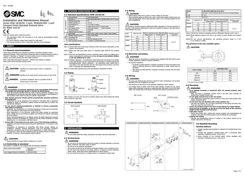
  9. SMC Networks 50-VFE User manual

SMC Networks 50-VFE User manual

50-VFE-SMY62EN
Page 1 of 4
Instruction Manual
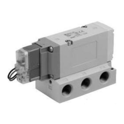
Solenoid operated 3 and 5 port valves
50-VFE/VPE-X60, 50-VFE3#90-X60 NAMUR
For ISO symbols see section 3.4.
The intended use of this product is to provide directional control to
pneumatic actuators (or similar industrial pneumatic equipment).
1 Safety Instructions
1.1 General safety instructions
These safety instructions are intended to prevent hazardous situations
and/or equipment damage. These instructions indicate the level of
potential hazard with the labels of “Caution,” “Warning” or “Danger.”
They are all important notes for safety and must be followed in addition
to International Standards (ISO/IEC)*1), and other safety regulations.
*1) ISO 4414: Pneumatic fluid power - General rules relating to systems.
ISO 4413: Hydraulic fluid power - General rules relating to systems.
IEC 60204-1: Safety of machinery - Electrical equipment of machines.
(Part 1: General requirements)
ISO 10218-1: Manipulating industrial robots -Safety. etc.
Refer to product catalogue, Operation Manual and Handling
Precautions for SMC Products for additional information.
Keep this manual in a safe place for future reference.
Caution
Caution indicates a hazard with a low level of risk which, if
not avoided, could result in minor or moderate injury.
Warning
Warning indicates a hazard with a medium level of risk
which, if not avoided, could result in death or serious injury.
Danger
Danger indicates a hazard with a high level of risk which, if
not avoided, will result in death or serious injury.
Warning
Always ensure compliance with relevant safety laws and
standards.
All work must be carried out in a safe manner by a qualified person in
compliance with applicable national regulations.
The product is only suitable for use in Zones 1 and 2.
Do not open when energised.
Do not energise both solenoids at the same time, as this can cause
higher surface temperatures than under normal operating conditions.
Do not refurbish the flameproof joints.
1 Safety Instructions - continued
Electrostatic charge may cause an explosion hazard.
Avoid any actions that cause the generation of electrostatic charge,
such as rubbing with a dry cloth on coating face of product.
Electrostatic charges on the non-metallic parts of the equipment shall
be avoided.
This product has components made of aluminium alloy. When
mounting this product, it must be installed such that, even in the event
of rare incidents, ignition sources due to impact and friction sparks are
excluded.
Use of 50-VFE3000/5000-X60 5-port valve as a 3-port valve
Series 50-VFE3000/5000-X60 valves can be used as normally closed
(N.C.) or normally open (N.O.) 3 port valves by closing one of the
cylinder ports (A or B) with a plug (see Table 1).
Note: Do not exceed the maximum specified operating frequency.
Plug position
2(B) port (CYL.1 port)
4(A) port (CYL.2 port)
Switching type
N.C.
N.O.
Solenoid
Single
Double
Table 1
1.2 Special conditions for safe use
Warning
The solenoid valves are provided with special fasteners of property
class A2-50.
The manufacturer shall be contacted for information regarding the
flameproof joints.
2 Specifications
2.1 General specifications
SERIES 50-VFE3000/5000-X60 SOLENOID VALVE
Series
50-VFE3000
50-VFE5000
Fluid
Air and inert gas
Operating
pressure
range
2 position single
0.15 to 0.9 MPa
3 position
2 position double
0.1 to 0.9 MPa
Ambient and fluid temperature
(No freezing)
-10 to 50°C (T5)
-10 to 40°C (T6)
Max. operating
frequency(1)
2 position single
1 Hz
2 position double
3 position
Lubrication
Not required
Mounting position
Unrestricted
Impact/Vibration resistance (2)
150/30 m/s2
SERIES 50-VPE500/700-X60 SOLENOID VALVE
Fluid
Air and inert gas
Type of actuation
N.C or N.O. (convertible)
Pilot style
Internal pilot
External pilot
Operating pressure range
0.2 to 0.8 MPa
Supply
pressure
-101.2 kPa to
0.8 MPa
External pilot
pressure
0.2 to 0.8 MPa
Ambient and fluid temperature
(No freezing)
-10 to 50°C (T5)
-10 to 40°C (T6)
Max. operating frequency(1)
1Hz
Lubrication
Not required
Mounting position
Unrestricted
Impact/Vibration resistance (2)
150/30 m/s2
2 Specifications - continued
SERIES 50-VFE3#90-X60 NAMUR SOLENOID VALVE
Fluid
Air and inert gas
Type of actuation
N.C or N.O. (convertible)
Operating pressure range
0.15 to 0.9 MPa
Ambient and fluid temperature
(No freezing)
-10 to 50°C (T5)
-10 to 40°C (T6)
Max. operating frequency(1)
1Hz
Lubrication
Not required
Mounting position
NAMUR Interface
Impact/Vibration resistance (2)
150/30 m/s2
Note 1) Do not exceed the maximum specified operating frequency.
Note 2) Impact resistance: There should be no malfunction of the valve after testing
along the valve axis and at right angles to the valve and armature. Carry out each
test with the valve energised and de-energised (value at initial stage).
Vibration resistance: There should be no malfunction of the valve after testing using
a 8.3 to 2000Hz sweep along the valve axis and at right angles to the valve and
armature. Carry out each test with the valve energised and de-energised (value at
initial stage).
SERIES 50-VF3-#-X60 PILOT VALVE
External connection method
Metal conduit type/ (Cable gland type)
Coil rated voltage
AC (50/60 Hz)
100, 200, 12, 24,
48, 110, 220, 240V
DC
24, 12, 6, 48, 110V
Allowable voltage fluctuation
-15% to +10% of rated voltage
Coil insulation type
Type B
Apparent power
AC
Inrush
9.1VA (50Hz) 7.8VA (60Hz)
Holding
6.2VA (50Hz) 4.6VA (60Hz)
Power
consumption
DC
3.5W
3.9W (48, 110V)
Electric circuit
Non-polar type
Batch codes and Construction month:
The product control number is shown by two characters and two figures.
The character shows Year and Month of manufacturing.
The figures show a serial number stamp.
This stamp indicates the year and month of production, the month of the
production request and the order in which work order has been
processed.
3 Installation
3.1 Installation Warning
Do not install the product unless the safety instructions have been read
and understood.
3.2 Environment Warning
The product is only suitable for use in Zones 1 and 2.
Do not use in an environment where corrosive gases, chemicals, salt
water or steam are present.
Do not expose to direct sunlight. Use a suitable protective cover.
Do not install in a location subject to vibration or impact in excess of
the product’s specifications.
Do not mount in a location exposed to radiant heat that would result in
temperatures in excess of the product’s specifications.
When the solenoid valve is mounted in a control panel or is energised
for a long time, make sure the ambient temperature is within the valve
specification range.
3 Installation - continued
3.3 Piping Caution
Before connecting piping make sure to clean up chips, cutting oil, dust
etc.
When installing piping or fittings, ensure sealant material does not
enter inside the port. When using seal tape, leave 1 thread exposed
on the end of the pipe/fitting.
Tighten fittings to the specified tightening torque, see Table 2.
Thread
Tightening Torque (N•m)
M5
1 to 1.5
1/8
3 to 5
1/4
8 to 12
3/8
15 to 20
1/2
20 to 25
Table 2
3.4 ISO symbols
50-VPE5(7)42(R)
N.C.
N.O.
C.O.
50-VFE3/5000
5/2 Single
5/2 Double
5/3 Closed
centre
5/3 Exhaust
centre
5/3 Pressure
centre
3.5 Electrical entry (see Figure 1)
The terminal box can be rotated 300° about plane ‘A’.
Loosen screw ‘C’ and rotate the terminal box to the desired position.
Re-tighten screw to lock the terminal box in position.
The cover can be rotated 360° about plane ‘B’.
Undo screw ‘D’ and rotate the cover to the desired position – there are
4 positions –in increments of 90°.
Re-assemble screw to lock the cover in place.
Construction
Year / M onth Jan Feb M ar Apr M ay Jun Jul Aug Sep Oct Nov Dec
2019 Xo XP XQ XR XS XT XU XV XW XX Xy XZ
2020 yo yP yQ yR yS yT yU yV yW yX yy yZ
… … … … … … … … … … … … …
2024 Co CP CQ CR CS CT CU CV CW CX Cy CZ
Production batch codes
ATEX Classification:
II 2G Ex db IIC T6..(T5) Gb -10°C ≤ Ta ≤ +40°C(+50°C)
Certificate reference: KEMA 09ATEX0024 X
‘X’ Special conditions of safe use apply, see section 1.2.
ORIGINAL INSTRUCTIONS
Refer to Declaration of
Conformity for relevant
Directives
50-VFE-SMY62EN
Page 2 of 4
3 Installation - continued
Figure 1
3.5 Electrical Connection Caution
The power supply should be fitted with a switch or circuit breaker in
close proximity to the equipment and within easy reach of the operator.
It shall be clearly marked as the disconnecting device for the
equipment.
Avoid mis-wiring, as this can cause malfunction, damage and fire to
the product.
Use voltage that is within –15% to +10% of the rated voltage.
Application of incorrect voltage may cause malfunction or damage.
Use electrical circuits that do not generate chattering in their contacts.
Do not bend or pull cables repeatedly.
The power supply should be fitted with a suitable fuse, see Table 3.
Voltage
Appropriate fuse
(Amps)
AC
(50/60Hz)
100, 200, 12, 24,
48, 110, 220, 240V
1.5
DC
24, 12, 6, 48, 110V
Table 3
When connecting C-R element parallel to switching element, leakage
current flows through C-R element and the leakage voltage increases.
Figure 2
Ensure that the voltage leakage across the coil is as follows:
With AC coil: 15% or less of rated voltage.
With DC coil: 3% or less of rated voltage
Danger
Disconnect power supply before removing or making electrical
connections.
Cable entrymust be made usingmetal conduit or cable gland, see
Figure 5 and Figure 7.
Assembly of terminals to cable
Use cables with insulated wires, stranded, 1.04 to 2.63 mm2.
Terminate wires using crimp terminals (part number V2-M4 –made by
J.S.T.MFG.CO.,LTD or equivalent) to suit M4 screws.
Use crimping tool to attach terminals (part number YNT-1614 –made
by J.S.T.MFG.CO.,LTD or equivalent).
3 Installation - continued
After crimping, check the crimp by slightly pulling the insulated wire.
Internal earthing: Use at least 2.63 mm2or large wire
Assembly of external ground terminal to cable
Use cables with insulated wires, stranded, 4 to 6.64 mm2.
Terminate wires using crimp terminals (part number V5.5-S4 –made
by J.S.T.MFG.CO.,LTD or equivalent) to suit M4 screws.
Use crimping tool to attach terminals (part number YNT-1210S –made
by J.S.T.MFG.CO.,LTD or equivalent).
After crimping, check the crimp by slightly pulling the insulated wire.
Assembly of cable to valve
Ensure cables have correct crimp terminals to suit M4 screws.
Ensure the terminal box is locked in position.
Remove the four M4 x 10 screws and carefully remove terminal cover
ensuring mating surfaces are not damaged.
Feed cable through cable entry and attach wires to valve using M4 x 6
round head screws with M4 washers.
Ensure wires are correctly connected to the corresponding terminals.
Replace terminal cover, ensuring mating surfaces are not damaged,
and torque tighten cover screws to 1.35 to 1.45 N•m.
Figure 3
Figure 4
Metal conduit threaded type entry
Metal conduit should be heavy gauge steel with parallel M20 thread.
Ensure a minimum engagement of five full threads and secure with
locknut.
During assembly, prevent excessive force being applied to the
solenoid valve, by using a spanner on the flats provided on the valve.
In humid environment, coat the threads with a liquid gasket.
3 Installation - continued
Figure 5
Be sure to protect the cable used for earth from twisting.
Figure 6
Flameproof enclosure cable gland (not supplied) type entry
The cable gland connector must have the following certification.
ATEX
II 2 G Ex db IIC Gb
Select cable gland connector applicable to flexible cable O/D and with
a parallel M20 or ½ NPT thread.
Follow instructions supplied with cable gland on how to assemble to
cable.
Ensure a minimum engagement of five full threads and secure with
locknut.
During assembly, prevent excessive force being applied to the
solenoid valve, by using a spanner on the flats provided on the valve.
In humid environment, coat the threads with a liquid gasket. .
Use a cable and cable gland rated for at least +90°C for temperature
class T5.
Figure 7
3 Installation - continued
Figure 8
3.6 Lubrication Caution
SMC products have been lubricated for life at manufacture, and do not
require lubrication in service.
If a lubricant is used in the system, refer to catalogue for details.
4 Settings
4.1 Manual Override Caution
Since connected equipment will operate when the manual override is
activated, confirm that conditions are safe prior to activation.
Non-locking push type (tool required)
Push down the manual override button with a small screwdriver, etc.
until it stops ON.
Hold this position for the duration of the check (ON position).
The manual override will return when released to the OFF position.
Figure 9
Slotted locking push type (tool required)
Push down the manual override button with a small flat head
screwdriver until it stops and turn 90° clockwise to lock (ON position).
Turn anti-clockwise to release to the OFF position.
Figure 10
50-VFE-SMY62EN
Page 3 of 4
4 Settings - continued
4.2 Change of Actuation
50-VPE500-X60 and 50-VPE700-X60 Body ported
Figure 11
When changing the actuation from normally closed to normally open
type, remove the end platefrom the body and reset the ▼mark on the
end plate to correspond with the ‘NO’ mark on the body as shown in
Figure 11.
Refer to Table 4 for piping.
Port
Actuation
1(P)
2(A)
3(R)
N.C.
Inlet side
Outlet side
Exhaust side
N.O.
Exhaust side
Outlet side
Inlet side
Table 4
5 How to Order
Please contact SMC for details.
6 Outline Dimensions
Please contact SMC for details.
7 Maintenance
7.1 General Maintenance Caution
Not following proper maintenance procedures could cause the product
to malfunction and lead to equipment damage.
If handled improperly, compressed air can be dangerous.
Maintenance of pneumatic systems should be performed only by
qualified personnel.
Before performing maintenance, turn off the power supply and be sure
to cut off the supply pressure. Confirm that the air is released to
atmosphere.
After installation and maintenance, apply operating pressure and
power to the equipment and perform appropriate functional and
leakage tests to make sure the equipment is installed correctly.
If any electricalconnections are disturbed duringmaintenance, ensure
they are reconnected correctly and safety checks are carried out as
required to ensure continued compliance with applicable national
regulations.
Do not make any modification to the product.
Do not disassemble the product, unless required by installation or
maintenance instructions.
7.2 Mounting Danger
Never add or remove a valve from the manifold when energised.
Never remove terminal box cover when power is connected to the
manifold.
Never disconnect or reconnect cables or connectors when power is
connected to the valves. Caution
Be sure to cut off power and the air supply and confirm that no air is
left in actuators, piping and manifolds before disassembling, as
remaining air may cause an accident.
Before assembly and installations, confirm that rubber parts such as
gaskets and O rings are assembled to every block. If rubber parts are
missing, air leakage may occur.
Manifold 50-VFE-X60:
Removal of valve
Remove screws and gently lift valve from manifold.
Ensure gasket and spacer are not misplaced or damaged.
Disconnect electrical connection.
7 Maintenance - continued
Assembly of valve
Reconnect the electrical connection.
Assemble valve to the manifold in the correct orientation, ensuring
spacer and all gaskets are present.
Torque tighten screws to torque shown in Table 5.
Valve Series
Appropriate tightening torque
N•m
50-VFE3000
1.3 to 1.5
50-VFE5000
1.3 to 1.5
Table 5
50-VFE-X60 Valve mounting:
Figure 12
7 Maintenance - continued
Figure 13
Figure 14
7 Maintenance - continued
Figure 15
Figure 16
50-VFE-SMY62EN
Page 4 of 4
7 Maintenance - continued
Figure 17
50-VFE3190-X60 NAMUR Valve mounting:
Figure 18
The NAMUR solenoid valve can be attached with 2 mounting bolts.
The position of the coding stud hole is up to the manufacturer and thus
also determines the location of the coding stud.
Caution
Ensure all gaskets are present before mounting valves.
Do not let foreign matter stick to gaskets or sealing faces of the valve
to avoid air leaks.
8 Limitations of Use
8.1 Limited warranty and Disclaimer/Compliance Requirements
Refer to Handling Precautions for SMC Products.
Warning
Refer to the ATEX classification for the product.
The product is suitable for use in ATEX Zones 1 and 2 applications
only.
Do not operate the valves above the maximum specified operating
frequency of 1 Hz.
9 Product disposal
This product should not be disposed of as municipal waste. Check your
local regulations and guidelines to dispose this product correctly, in order
to reduce the impact on human health and the environment.
1 Contacts
Refer to www.smcworld.com or www.smc.eu for contacts.
URL :
http// www.smcworld.com (Global) http// www.smc.eu (Europe)
'SMC Corporation, Akihabara UDX15F, 4-14-1, Sotokanda, Chiyoda-ku, Tokyo 101
0021
Specifications are subject to change without prior notice from the manufacturer.
© 2020 SMC Corporation All Rights Reserved.
Template DKP50047-F-085J

This manual suits for next models

1

Other SMC Networks Control Unit manuals

SMC Networks SX10 Series User manual

SMC Networks

SMC Networks SX10 Series User manual

SMC Networks AK Series User manual

SMC Networks

SMC Networks AK Series User manual

SMC Networks EX260-SEN2-X205 User manual

SMC Networks

SMC Networks EX260-SEN2-X205 User manual

SMC Networks XT323-4 Manual

SMC Networks

SMC Networks XT323-4 Manual

SMC Networks EX250-SCF1-X200 User manual

SMC Networks

SMC Networks EX250-SCF1-X200 User manual

SMC Networks EX140-SMJ1 Series User manual

SMC Networks

SMC Networks EX140-SMJ1 Series User manual

SMC Networks S070 Series User manual

SMC Networks

SMC Networks S070 Series User manual

SMC Networks VDW 10 Manual

SMC Networks

SMC Networks VDW 10 Manual

SMC Networks ASR Series User manual

SMC Networks

SMC Networks ASR Series User manual

SMC Networks IL220-02 L Series User manual

SMC Networks

SMC Networks IL220-02 L Series User manual

SMC Networks VM1000 Series User manual

SMC Networks

SMC Networks VM1000 Series User manual

SMC Networks XLH16 User manual

SMC Networks

SMC Networks XLH16 User manual

SMC Networks S0700 Manual

SMC Networks

SMC Networks S0700 Manual

SMC Networks VX21 Manual

SMC Networks

SMC Networks VX21 Manual

SMC Networks AV2000-02-1 User manual

SMC Networks

SMC Networks AV2000-02-1 User manual

SMC Networks SY3000 SERIES Installation manual

SMC Networks

SMC Networks SY3000 SERIES Installation manual

SMC Networks VEX5 Series User manual

SMC Networks

SMC Networks VEX5 Series User manual

SMC Networks VP 46 Series User manual

SMC Networks

SMC Networks VP 46 Series User manual

SMC Networks IL220 Series User manual

SMC Networks

SMC Networks IL220 Series User manual

SMC Networks VF1000 Series Manual

SMC Networks

SMC Networks VF1000 Series Manual

SMC Networks VHS20 Series User manual

SMC Networks

SMC Networks VHS20 Series User manual

SMC Networks EX245-FPS1 User manual

SMC Networks

SMC Networks EX245-FPS1 User manual

SMC Networks VHS20-D Series User manual

SMC Networks

SMC Networks VHS20-D Series User manual

SMC Networks VR51 Series User manual

SMC Networks

SMC Networks VR51 Series User manual

Popular Control Unit manuals by other brands

Terra UC380 user manual

Terra

Terra UC380 user manual

Lenze E94AZHY0025 Mounting instructions

Lenze

Lenze E94AZHY0025 Mounting instructions

Definox DPX1EBC Maintenance notice

Definox

Definox DPX1EBC Maintenance notice

LSI MegaRAID LSIiBBU01 Quick installation guide

LSI

LSI MegaRAID LSIiBBU01 Quick installation guide

Compac OPT SCR200 installation manual

Compac

Compac OPT SCR200 installation manual

Arduino HM-11 user manual

Arduino

Arduino HM-11 user manual

schmersal SRB 304ST operating instructions

schmersal

schmersal SRB 304ST operating instructions

DAZE Dynamic Power Manager installation manual

DAZE

DAZE Dynamic Power Manager installation manual

Zamel EXTA EDM-01 instruction manual

Zamel

Zamel EXTA EDM-01 instruction manual

SpeedTurtle Easy Flash Module 3.0 user manual

SpeedTurtle

SpeedTurtle Easy Flash Module 3.0 user manual

entegris NT 6300 user guide

entegris

entegris NT 6300 user guide

Franklin Wireless S600 manual

Franklin Wireless

Franklin Wireless S600 manual

Baldwin Boxall BT10 operating instructions

Baldwin Boxall

Baldwin Boxall BT10 operating instructions

Emerson ALCO Thermo TX6 installation instructions

Emerson

Emerson ALCO Thermo TX6 installation instructions

Marvell Avastar SP88W8782-MA0 user guide

Marvell

Marvell Avastar SP88W8782-MA0 user guide

DOLD SAFEMASTER PRO UG 6951 user manual

DOLD

DOLD SAFEMASTER PRO UG 6951 user manual

Dataton SMARTPAX QC Product Sheets

Dataton

Dataton SMARTPAX QC Product Sheets

Valmet Flowrox PVEG Installation, operation and maintenance instructions

Valmet

Valmet Flowrox PVEG Installation, operation and maintenance instructions

manuals.online logo
manuals.online logoBrands
  • About & Mission
  • Contact us
  • Privacy Policy
  • Terms and Conditions

Copyright 2025 Manuals.Online. All Rights Reserved.