manuals.online logo
Brands
  1. Home
  2. •
  3. Brands
  4. •
  5. SMC Networks
  6. •
  7. Dehumidifier
  8. •
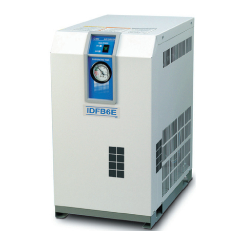
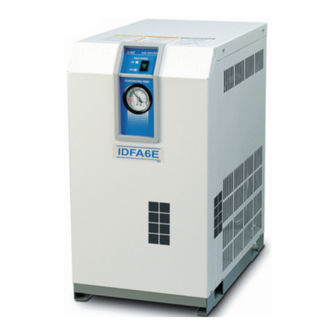
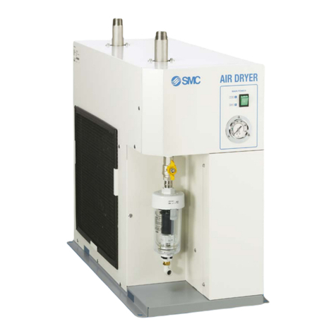
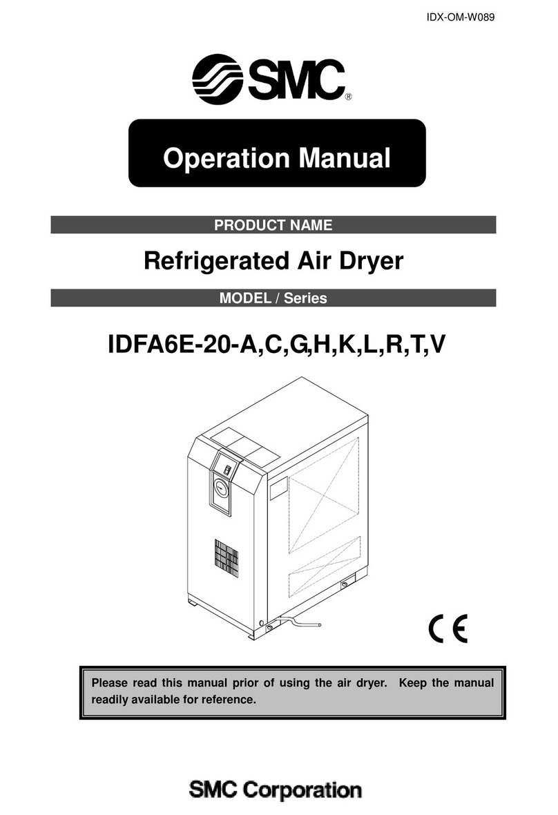
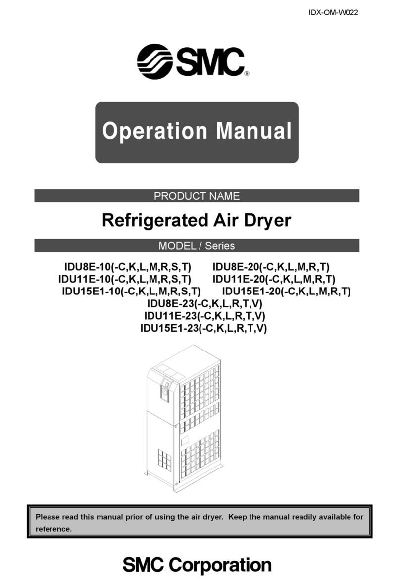
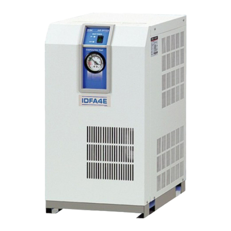
  9. SMC Networks IDF Series User manual

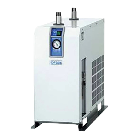
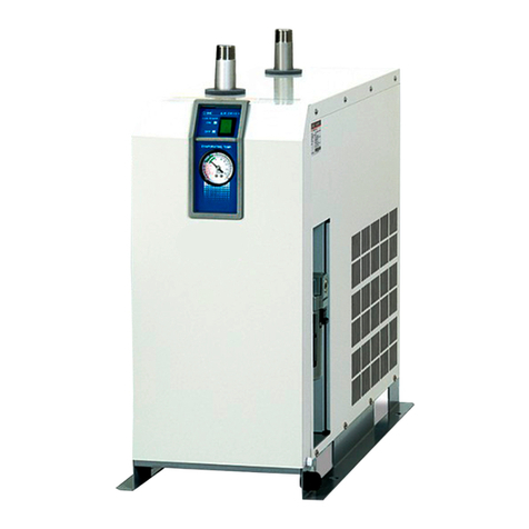
SMC Networks IDF Series User manual

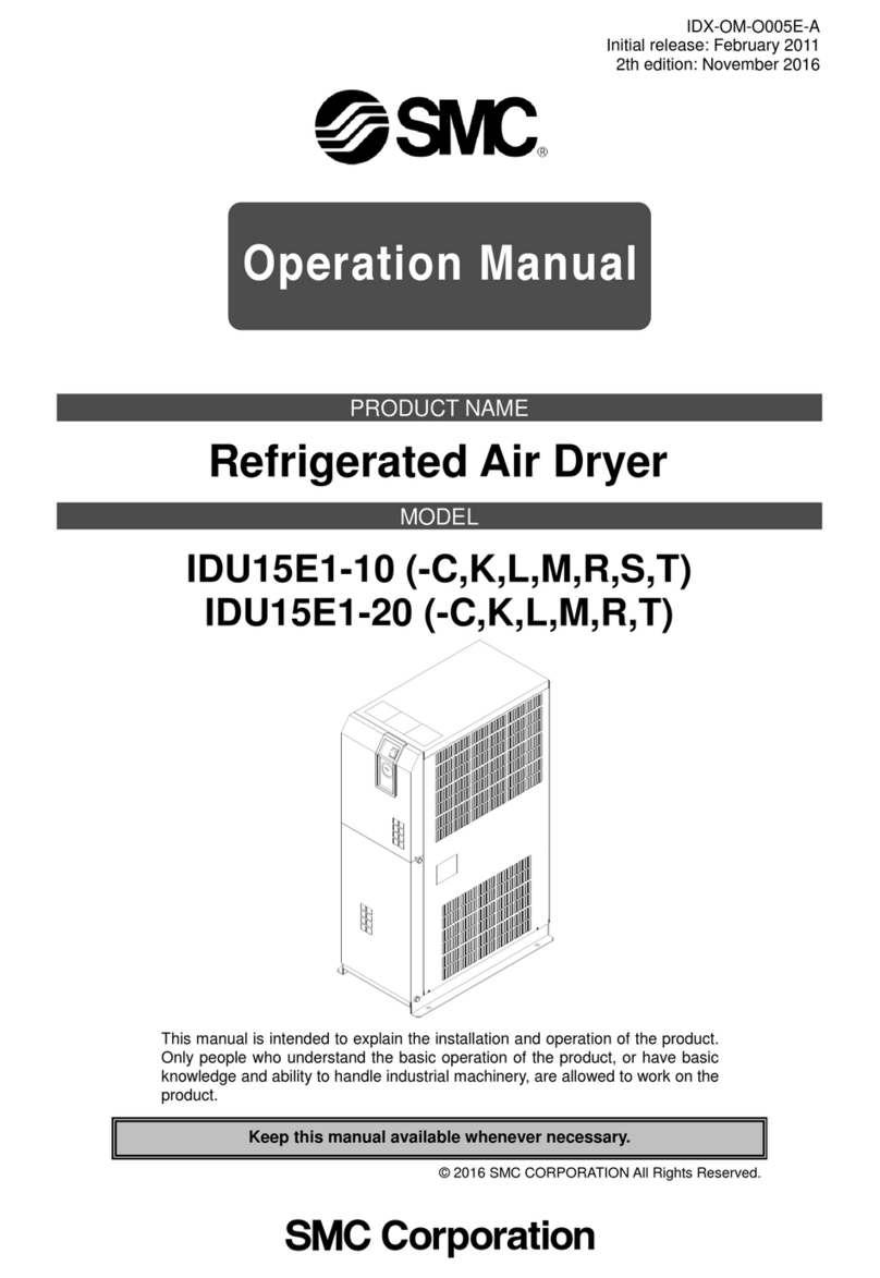
CAT.NAS30-8F
Standard temperature air inlet [Series IDF]
IDF1E, 2E, 3E, 4E, 6E, 8E,11E,15E, 22E, 37E, 55E, 75E, 120D, 150D, 190D, 240D, 370B
High temperature air inlet [Series IDU]
IDU3E, 4E, 6E, 8E,11E,15E, 22E, 37E, 55E, 75E
NEW NEW
Improved corrosion resistance
with the stainless steel heat exchanger
(IDF4E to 75E/IDU3E to 75E)
Zero ozone depletion potential
RefrigerantRefrigerantRefrigerant
Up to %
Air flowAir flow
capacitycapacity
Air flow
capacity Up to %
Increased by Reduced by
PowerPower
consumptionconsumption
Power
consumption
R134a (HFC)R134a (HFC)
R407C (HFC)R407C (HFC)
R134a (HFC)
R407C (HFC)
(SMC comparison) (SMC comparison)
Series IDF/IDU
Refrigerated Air Dryers
An air dryer removes the vapor from the moist compressed air delivered by the
compressor, and prevents it from causing the pneumatic equipment to fail.
Protect Pneumatic Equipment from Moisture!Protect Pneumatic Equipment from Moisture!Protect Pneumatic Equipment from Moisture!
Effects of moisture on equipment
Decomposition of auto drain
caused by rusting inside pipes
Generation of water droplets
Malfunctioning of valves and
actuators caused by dripping grease
Refrigerated Air Dryers Series IDF/IDU
Compressed air contains moisture (water vapor, droplets), oil, debris and other foreign
matter. Filters and mist separators can be used to remove droplets, oil, debris, and so on,
but a dryer is necessary to remove water vapor.
The Importance of Dryers
Moisture
Odors
Particulates 3 µm or
more in diameter
(solids)
Particulates less than
3µm in diameter
(solids)
(Water vapor)
(Debris)
Compressor
After-
cooler
Air Tank
RefrigeratedRefrigerated
Air DryerAir Dryer Micro Mist
Separator
Filter
Main Line
Filter
Mist
Separator
Odor
Removal
Filter
(Deodorization)
Refrigerated
Air Dryer
Impurities
in the air
Compressed air
containing no
impurities
Impurities in
compressed air
Dry air
The primary job of a dryer is
dehumidification.
Air containing
moisture
Air containingAir containing
moisturemoisture
Air containing
moisture
Features 1
P
For ScrewCompressors
[When an aftercooler is not installed, Refrigerated air dryer inlet temperature: ambient temperature + 59°F (15°C), Membrane air dryer inlet temperature: 77°F (25°C)]
P
For ScrewCompressors [When an aftercooler is installed, Refrigerated air dryer inlet temperature: 95°F (35°C) or 104°F (40°C), Membrane air dryer inlet temperature: 77°F (25°C)]
P
For Reciprocating Compressors
[Aftercooler inlet: 50°F (180°C) or 102°F (70°C), Refrigerated air dryer inlet temperature: 95°F (35°C) or 104°F (40°C), Membrane air dryer inlet temperature: 77°F (25°C)]
∗Shows standard combinations. The suffix numbers of the model indicate port size,power supply, etc.
Refer to “How to Order” on pages 5, 9, 12, 15 and 18 for details on dryers and refer to “SMC Best Pneumatics” for other equipment.
∗The symbol “—” in the table indicates that no such equipment exists.
∗The figures for air flow capacity corresponding to air compressor output are provided for reference only.
∗The below table applies to the air pressure dew point 50°F (10°C) [at 100psi (0.7 MPa)]. In cases where other dew points are needed, refer to pages 3 and 4
(Model Selection) in this catalog.
Note 1) Air flow capacity conditions Suction condition ............................ 89.6°F (32°C), Atmospheric pressure, Relative humidity 65%
ANR conversion .............................. 68°F (20°C), Atmospheric pressure, Relative humidity 65%
Note 2) Air-cooled aftercooler Inlet air temperature ....................... 158°F (70°C)
Ambient temperature ...................... 89.6°F (32°C)
Water-cooled aftercooler Inlet air temperature ....................... 58°F (70°C) (Screw compressors), 358°F (180°C) (Reciprocating compressors, 158°F (70°C) for HAW2,7)
Cooling water inlet temperature ...... 86°F (30°C)
Note 3) Series lDF Inlet air temperature ....................... 95°F (35°C) saturation (IDF1E to 37E), 105°F (40°C) saturation (IDF55E to 75E, IDF120D to 240D)
Ambient temperature ...................... 89.6°F (32°C)
Note 4) Series lDU Inlet air temperature ....................... 131°F (55°C) saturation (lDU3E to 75E)
Ambient temperature ...................... 89.6°F (32°C)
Note 5) Series lDG Inlet air temperature ....................... 77°F (25°C)
Ambient temperature ...................... 77°F (25°C)
QuickReference Guide to Air Preparation Equipment
0.75
1.5
2.2
3.7
5.5
7.5
11
15
22
27
37
55
75
110
150
220
0.1
0.2
0.3
0.5
0.7
1.0
1.5
2.0
3.0
3.5
5.0
7.5
10.0
15.0
20.0
30.0
0.10
0.19
0.29
0.48
0.67
0.96
1.44
1.92
2.88
3.36
4.8
7.2
9.6
14.4
19.2
28.8
AT6C-04
AT6C-04
AT6C-04
AT6C-04
AT6C-04
AT11C-06
AT11C-06
AT22C-14
AT22C-14
AT37C-14
AT37C-14
AT55C-20
AT75C-20
AT125C-30
AT150C-40
AT220C-40
HAA7-06
HAA7-06
HAA7-06
HAA7-06
HAA7-06
HAA7-06
HAA15-10
HAA15-10
HAA22-14
HAA37-14
HAA37-14
—
—
—
—
—
HAW2-04
HAW2-04
HAW2-04
HAW7-06
HAW7-06
HAW7-06
HAW22-14
HAW22-14
HAW37-14
HAW37-14
HAW55-20
HAW75-20
HAW110-30
—
—
—
AFF2C-02
AFF2C-02
AFF2C-02
AFF4C-03
AFF4C-03
AFF8C-04
AFF8C-04
AFF11C-06
AFF22C-10
AFF22C-10
AFF37B-14
AFF75AB-20
AFF75AB-20
AFF125A-30
AFF125A-30
AFF220A-40
IDF1E
IDF2E
IDF3E
IDF4E
IDF6E
IDF8E
IDF11E
IDF15E
IDF22E
IDF22E
IDF37E
IDF55E
IDF75E
IDF120D
IDF120D
IDF190D
IDF1E
IDF2E
IDF3E
IDF4E
IDF6E
IDF8E
IDF11E
IDF15E
IDF15E
IDF22E
IDF37E
IDF55E
IDF75E
IDF120D
IDF120D
IDF150D
Air compressor Main line
Air tank Aftercooler Note 2)
Air-cooled
Water-cooled
Sub line
Main line
filter
Refrigerated
air dryer Note 3)
50 Hz 60 Hz
Output
(kW)
Air flow capacity (m
3
/min)
Note 1)
Suction
condition
(89.6°F, 32°C)
ANR
conversion
(68°F, 20°C)
1.5
2.2
3.7
5.5
7.5
11
15
22
37
55
75
110
150
220
0.16
0.245
0.44
0.72
1.2
1.8
2.6
4
6.6
9.5
13
19
28.5
45
0.15
0.24
0.42
0.69
1.15
1.7
2.5
3.8
6.3
9.1
12.5
18.3
27.4
43.2
HAA7-06
HAA7-06
HAA7-06
HAA7-06
HAA15-10
HAA15-10
HAA15-10
HAA37-14
—
—
—
—
—
—
HAW2-04
HAW2-04
HAW7-06
HAW7-06
HAW22-14
HAW22-14
HAW22-14
HAW37-14
HAW55-20
HAW75-20
HAW110-30
—
—
—
IDF2E
IDF3E
IDF4E
IDF6E
IDF8E
IDF15E
IDF15E
IDF22E
IDF55E
IDF75E
IDF120D
IDF120D
IDF190D
IDF240D
IDF2E
IDF3E
IDF4E
IDF6E
IDF8E
IDF11E
IDF15E
IDF22E
IDF37E
IDF55E
IDF75E
IDF120D
IDF150D
IDF240D
Air compressor Main line
Aftercooler Note 2)
Air-cooled Water-cooled
Sub line
Refrigerated air dryer Note 3)
50 Hz 60 Hz
Output
(kW)
Suction
condition
(89.6°F, 32°C)
ANR
conversion
(68°F, 20°C)
1.5
2.2
3.7
5.5
7.5
11
15
22
37
55
75
110
150
220
0.16
0.245
0.44
0.72
1.2
1.8
2.6
4
6.6
9.5
13
19
28.5
45
0.15
0.24
0.42
0.69
1.15
1.7
2.5
3.8
6.3
9.1
12.5
18.3
27.4
43.2
IDU3E
IDU3E
IDU4E
IDU6E
IDU8E
IDU15E
IDU15E
IDU22E
IDU55E
IDU75E
—
—
—
—
IDU3E
IDU3E
IDU4E
IDU6E
IDU8E
IDU11E
IDU15E
IDU22E
IDU37E
IDU55E
IDU75E
—
—
—
Air compressor
Air-cooled aftercooler integrated type Note 4)
refrigerated air dryer
50 Hz
Sub line
60 Hz
Output
(kW)
Suction
condition
(89.6°F, 32°C)
ANR
conversion
(68°F, 20°C)
AM150C-02
AM150C-02
AM150C-02
AM250C-03
AM250C-03
AM350C-04
AM350C-04
AM450C-06
AM550C-10
AM550C-10
AM650-14
AM850-20
AM850-20
—
—
—
Local line
Mist
separator
AMH150C-02
AMH150C-02
AMH250C-02
AMH250C-03
AMH350C-03
AMH350C-04
AMH450C-04
AMH450C-06
AMH550C-10
AMH550C-10
AMH650-14
AMH850-20
AMH850-20
—
—
—
Micro mist
separator
with pre-filter
AMD150C-02
AMD150C-02
AMD250C-02
AMD250C-03
AMD350C-03
AMD350C-04
AMD450C-04
AMD450C-06
AMD550C-10
AMD550C-10
AMD650-14
AMD850-20
AMD850-20
AMD910-30
AMD910-30
AMD1010-40
Micro mist
separator
AME150C-02
AME150C-02
AME250C-02
AME250C-03
AME350C-03
AME350C-04
AME450C-04
AME450C-06
AME550C-10
AME550C-10
AME650-14
AME850-20
AME850-20
—
—
—
Super mist
separator
AMF150C-02
AMF150C-02
AMF250C-02
AMF250C-03
AMF350C-03
AMF350C-04
AMF450C-04
AMF450C-06
AMF550C-10
AMF550C-10
AMF650-14
AMF850-20
AMF850-20
AMF910-30
AMF910-30
AMF1000-40
Odor
removal
filter
IDG10-02
IDG20-02
IDG30-02
IDG50-03
IDG75-04
IDG100-04
—
—
—
—
—
—
—
—
—
—
AM150C-02
AM150C-02
AM250C-03
AM250C-03
AM350C-04
AM450C-06
AM550C-10
AM650-14
AM850-20
AM850-20
—
—
—
—
Local line
Mist
separator
AMH150C-02
AMH250C-03
AMH250C-03
AMH350C-04
AMH450C-06
AMH450C-06
AMH550C-10
AMH650-14
AMH850-20
AMH850-20
—
—
—
—
Micro mist
separator
with pre-filter
AMD150C-02
AMD250C-03
AMD250C-03
AMD350C-04
AMD450C-06
AMD450C-06
AMD550C-10
AMD650-14
AMD850-20
AMD850-20
AMD910-30
AMD910-30
AMD1010-40
—
Micro mist
separator
AME150C-02
AME250C-03
AME250C-03
AME350C-04
AME450C-06
AME450C-06
AME550C-10
AME650-14
AME850-20
AME850-20
—
—
—
—
Super mist
separator
AMF150C-02
AMF250C-03
AMF250C-03
AMF350C-04
AMF450C-06
AMF450C-06
AMF550C-10
AMF650-14
AMF850-20
AMF850-20
AMF900-30
AMF900-30
AMF1000-40
—
Odor
removal
filter
IDG20-02
IDG30-02
IDG50-03
IDG75-04
—
—
—
—
—
—
—
—
—
—
AM150C-02
AM150C-02
AM250C-03
AM250C-03
AM350C-04
AM450C-06
AM550C-10
AM650-14
AM850-20
AM850-20
—
—
—
—
Local line
Mist
separator
AMH150C-02
AMH250C-03
AMH250C-03
AMH350C-04
AMH450C-06
AMH450C-06
AMH550C-10
AMH650-14
AMH850-20
AMH850-20
—
—
—
—
Micro mist
separator
with pre-filter
AMD150C-02
AMD250C-03
AMD250C-03
AMD350C-04
AMD450C-06
AMD450C-06
AMD550C-10
AMD650-14
AMD850-20
AMD850-20
AMD910-30
AMD910-30
AMD1010-40
—
Micro mist
separator
AME150C-02
AME250C-03
AME250C-03
AME350C-04
AME450C-06
AME450C-06
AME550C-10
AME650-14
AME850-20
AME850-20
—
—
—
—
Super mist
separator
AMF150C-02
AMF250C-03
AMF250C-03
AMF350C-04
AMF450C-06
AMF450C-06
AMF550C-10
AMF650-14
AMF850-20
AMF850-20
AMF900-30
AMF900-30
AMF1000-40
—
Odor
removal
filter
IDG20-02
IDG30-02
IDG50-03
IDG75-04
—
—
—
—
—
—
—
—
—
—
SMC Air Preparation Equipment
Membrane
air dryer
Note 5)
Membrane
air dryer
Note 5)
Membrane
air dryer
Note 5)
Air flow capacity (m
3
/min)
Note 1)
Air flow capacity (m
3
/min)
Note 1)
(1m3/min = 35.31 SCFM)
Features 2
P.5 to 8
P.9 to 11
P.12 to 14
Page
Model Refrigerant
Applicable air
compressor (kW)
50 Hz
0.1
0.2
0.32
0.52
0.75
1.22
1.65
2.8
3.9
5.7
8.4
11.0
20.0
25.0
32.0
43.0
54.0
60 Hz
Air flow capacity (m
3
/min [ANR])
Rated
inlet
condition
95°F,
100psi
(35°C,
0.7 MPa)
104°F,
100psi
(40°C,
0.7 MPa)
95°F, 100psi
(35°C,
0.7 MPa)
0.12
0.235
0.37
0.57
0.82
1.32
1.82
3.1
4.3
6.1
9.8
12.4
23.0
30.0
38.0
50.0
65.0
0.75
1.5
2.2
3.7
5.5
7.5
11
15
22
37
55
75
120
150
190
240
370
Rc 3/8
Rc 1/2
Rc 3/4
Rc 1
R 1
R1 1/2
R 2
65 (2 1/2B) flange
80 (3B) flange
100 (4B) flange
150 (6B) flange
Port size
R134a (HFC)
R407C (HFC)
R22
P.15 to 17
P.18 to 20
Page
Model Refrigerant
Applicable air
compressor (kW)
50 Hz
0.32
0.52
0.75
1.1
1.5
2.6
3.9
5.7
8.4
11.0
60 Hz
Air flow capacity (m
3
/min [ANR])
IDF1E
IDF2E
IDF3E
IDF4E
IDF6E
IDF8E
IDF11E
IDF15E
IDF22E
IDF37E
IDF55E
IDF75E
IDF120D
IDF150D
IDF190D
IDF240D
IDF370B
IDU3E
IDU4E
IDU6E
IDU8E
IDU11E
IDU15E
IDU22E
IDU37E
IDU55E
IDU75E
Rated
inlet
condition
131°F,
100psi
(55°C,
0.7 MPa)
0.37
0.57
0.82
1.2
1.7
2.8
4.3
6.1
9.8
12.5
2.2
3.7
5.5
7.5
11
15
22
37
55
75
Rc 3/8
Rc 1/2
Rc 3/4
Rc 1
R 1
R 1 1/2
R 2
Port size
R134a (HFC)
R407C (HFC)
Complies with CFC restrictions
Refrigerated Air Dryers
Series IDF
Standard temperature air inlet type
Rated inlet air temperature:
95, 104°F (35, 40°C)
Series IDU
High temperature air inlet type
Rated inlet air temperature:
131°F (55°C)
1. Standard Products
INDEX
INDEX
∗Refer to the separate catalog for dryer models conforming with foreign standards (CE and UL).
(1 m3/min = 35.3 cfm)
1
2. Options
P.21
P.22
P.23
P.24
P.25
Page
Description
Cool compressed air output
Anti-corrosive treatment for copper tube
Moderate pressure specification (up to 1.6 MPa)
(Auto drain bowl: Metal bowl with level gauge)
With a heavy-duty auto drain (applicable to moderate pressure)
With a motor type auto drain Note 1)
With a circuit breaker
Power supply terminal block connection
With a terminal block for power supply, operating/error signal and
remote operation
With a timer controlled solenoid valve type auto drain (applicable to moderate pressure)
Water-cooled condenser Note 1)
Applicable model Model
(Suffix: Option symbol)
IDF1E to 75E
IDF1E to 75E
IDF120D to 240D
IDF370B
IDU3E to 75E
IDF6E to 37E
IDU3E to 15E
IDF4E to 75E
IDF370B
IDU3E to 75E
IDF4E to 75E
IDF120D to 240D
IDU3E to 75E
IDF4E to 75E
IDF120D to 240D
IDF370B
IDU3E to 75E
IDF4E to 15E-10
IDU3E to 15E-10
IDF4E to 75E
IDU3E to 75E
IDU3E to 75E
IDF120D to 240D
IDFlE-l-A
IDFlE-l-C
IDFlD-l(-l)-C
IDF370B-60l-X204
IDUlE-l-C
IDFlE-l-K
IDUlE-l-K
IDFlE-l-L
IDF370B-60l-X205
IDUlE-l-L
IDFlE-l-M
IDFlD-l(-l)-M
IDUlE-l-M
IDFlE-l-R
IDFlD-l(-l)-R
IDF370B-60l-X202
IDUlE-l-R
IDFlE-10-S
IDUlE-10-S
IDFlE-l-T
IDUlE-l-T
IDUlE-l-V
IDFlD-l(-l)-W
3. Optional Accessories
4. Data (Condensed Water Calculation, Dew Point Conversion Chart) ··· P.37
5. Safety Instructions ··· Back page 1
P.26 to 36
Page
Description
Separately installed power transformer
Dedicated base for separately installed power transformer
Dust-protecting filter set
Bypass piping set
Foundation bolt set
Piping adapter
Mounting base adapter
Conversion piping set
Conversion bypass piping set
Note 1) Equipped with the IDF370B as standard.
INDEX
INDEX
2
The corrected air flow capacity, which considers the user’soperating conditions, is required for selecting air
dryer. Select using the following procedures.
IDF Selection Example IDU Selection Example
Read the correction
factors.
Obtain the correction factors A to
D suitable for your operating
condition from the table on the
next page.
2
Calculate the corrected
air flow capacity.
Obtain the corrected air flow
capacity from the following formula.
Corrected air flow capacity =
Air flow rate V(Correction
factor A x B x C x D)
Corrected air flow capacity = 0.3 m3/min V(0.82 x
0.96 x 1 x 0.88) = 0.43 m3/min
Corrected air flow capacity = 0.4 m3/min V(0.95 x
0.93 x 1 x 0.88) = 0.51 m3/min
4
Select the model.
Select the model with air flow capacity
which exceeds the corrected air flow
capacity from the specification table.
(For air flow capacity, refer to the data
E on page 4.)
According to the corrected air flow capacity of 0.43
m3/min, the
IDF4E
will be selected which air flow
capacity is 0.52 m3/min at 50 Hz.
According to the corrected air flow capacity of 0.51
m3/min, the
IDU4E
will be selected which air flow
capacity is 0.57 m3/min at 60 Hz.
5
Options Refer to pages 21 through to 25. Refer to pages 21 through to 25.
Refer to pages 5, 9 and 12.
Refer to pages 26 through to 36.
Refer to pages 15 and 18.
6
Finalize the model
number.
7
Select the optional
accessories.
8
Check the coefficient. Correction factor = 0.82 x 0.96 x 1 x 0.88 = 0.69
Max. coefficient value is 1.5 Correction factor is 1.5
when the calculation result is 1.5 or greater.
Correction factor = 0.95 x 0.93 x 1 x 0.88 = 0.78
Max. coefficient value is 1.5 Correction factor is 1.5
when the calculation result is 1.5 or greater.
3
Select the IDF or IDU. Select the IDF or IDU from inlet air temperature used.
• Inlet air temperature 41 to 122°F (5 to 50°C) ····· IDF
• Inlet air temperature 122 to 176°F (50 to 80°C) ····· IDU
1
Data
symbol
104 F (40°C)
95 F (35°C)
50 F (10°C)
72.5psi (0.5 MPa)
0.3 m3/min
50 Hz
A
B
C
D
—
—
0.82
0.96
1
0.88
—
—
Inlet air temperature
Ambient temperature
Outlet air pressure dew point
Inlet air pressure
Air flow rate
Power supply frequency
Condition
Note) Values obtained from “Correction Factors” on page 4.
Data
symbol
104 F (60°C)
95 F (35°C)
50 F (10°C)
72.5psi (0.5 MPa)
0.4 m3/min
60 Hz
A
B
C
D
—
—
0.95
0.93
1
0.88
—
—
Inlet air temperature
Ambient temperature
Outlet air pressure dew point
Inlet air pressure
Air flow rate
Power supply frequency
Condition
Note) Values obtained from “Correction Factors” on page 4.
Series IDF/IDU
Model Selection
Correction
factor
Note)
Correction
factor
Note)
3
Data A: Inlet Air Temperature
Correction Factors
Data C: Outlet Air Pressure
Dew Point
Data B: Ambient Temperature
Data D: Inlet Air Pressure
Data E: Air Flow Capacity
Series IDF
IDF1E to 75E,
120D to 240D, 370B
Series IDU
IDU3E to 37E
Correction
factor
0.55
0.7
1
1.3
37.4°F (3°C)
41°F (5°C)
50°F (10°C)
59°F (15°C)
Outlet air pressure
dew point
Correction
factor
0.55
0.7
1
1.3
37.4°F (3°C)
41°F (5°C)
50°F (10°C)
59°F (15°C)
Outlet air pressure
dew point
IDU55E, 75E
Correction
factor
0.53
0.67
1
1.30
37.4°F (3°C)
41°F (5°C)
50°F (10°C)
59°F (15°C)
Outlet air pressure
dew point
Series IDF
Model IDF1E
0.10
0.12
IDF2E
0.20
0.235
IDF3E
0.32
0.37
IDF4E
0.52
0.57
IDF6E
0.75
0.82
IDF8E
1.22
1.32
IDF11E
1.65
1.82
IDF15E
2.8
3.1
IDF22E
3.9
4.3
IDF37E
5.7
6.1
IDF55E
8.4
9.8
IDF75E
11.0
12.4
Air flow capacity
m3/min (ANR)
50 Hz
60 Hz
Series IDU
Model IDU3E
0.32
0.37
IDU4E
0.52
0.57
IDU6E
0.75
0.82
IDU8E
1.1
1.2
IDU11E
1.5
1.7
IDU15E
2.6
2.8
IDU22E
3.9
4.3
IDU37E
5.7
6.1
IDU55E
8.4
9.8
IDU75E
11.0
12.5
Air flow capacity
m3/min (ANR)
50 Hz
60 Hz
Model IDF120D
20.0
23.0
Air flow capacity
m3/min (ANR)
50 Hz
60 Hz
IDF150D
25.0
30.0
IDF190D
32.0
38.0
IDF240D
43.0
50.0
IDF370B
54.0
65.0
Note) In the case of the option A (cool compressed air output), the air flow capacity is different. Refer to page 21 for details.
Series IDF
IDF1E to 37E
Inlet air temp.
Correction
factor
1.3
1
0.82
0.68
0.57
41 to 86°F (5 to 30°C)
95°F (35°C)
104°F (40°C)
113°F (45°C)
122°F (50°C)
IDF55E, 75E, 120D to 240D
Inlet air temp.
Correction
factor
1.35
1.25
1
0.8
0.6
41 to 86°F (5 to 30°C)
95°F (35°C)
104°F (40°C)
113°F (45°C)
122°F (50°C)
Series IDU
IDU3E to 37E
Inlet air temp.
Correction
factor
1.15
1.07
1
0.95
0.9
0.86
0.82
0.79
51 to 113°F (5 to 45°C)
122°F (50°C)
131°F (55°C)
140°F (60°C)
149°F (65°C)
158°F (70°C)
167°F (75°C)
176°F (80°C)
IDF370B
Inlet air temp.
Correction
factor
1.25
1.00
0.83
0.70
0.60
41 to 86°F (5 to 30°C)
95°F (35°C)
104°F (40°C)
113°F (45°C)
122°F (50°C)
IDU55E, 75E
Inlet air temp.
Correction
factor
1.21
1.10
1
0.87
0.76
0.74
0.72
0.70
51 to 113°F (5 to 45°C)
122°F (50°C)
131°F (55°C)
140°F (60°C)
149°F (65°C)
158°F (70°C)
167°F (75°C)
176°F (80°C)
IDF120D to 240D
Ambient temp.
Correction
factor
1.10
1.05
1
0.95
0.90
35.6 to 77°F (2 to 25°C)
86°F (30°C)
89.6°F(32°C)
95°F (35°C)
104°F (40°C)
IDU55E, 75E
Ambient temp.
Correction
factor
1.25
1.11
1
0.90
0.63
35.6 to 77°F (2 to 25°C)
86°F (30°C)
89.6°F(32°C)
95°F (35°C)
104°F (40°C)
Series IDF
IDF1E to 75E
Ambient temp.
Correction
factor
1.14
1.04
1
0.96
0.9
35.6 to 77°F (2 to 25°C)
86°F (30°C)
89.6°F(32°C)
95°F (35°C)
104°F (40°C)
Series IDU
IDU3E to 37E
Ambient temp.
Correction
factor
1.2
1.04
1
0.93
0.84
35.6 to 77°F (2 to 25°C)
86°F (30°C)
89.6°F(32°C)
95°F (35°C)
104°F (40°C)
Series IDF
IDF1E to 75E
Inlet air
pressure
psi (MPa)
Correction
factor
0.62
0.72
0.81
0.88
0.95
1
1.06
1.11
1.16
145 to 231
(1 to 1.6)
IDF120D to 370B
IInlet air
pressure
psi (MPa)
Correction
factor
0.68
0.77
0.84
0.90
0.95
1
1.03
1.06
1.08
Series IDU
IDU3E to 37E
Inlet air
pressure
psi (MPa)
Correction
factor
0.62
0.72
0.81
0.88
0.95
1
1.06
1.11
1.16
IDU55E, 75E
Inlet air
pressure
psi (MPa)
Correction
factor
0.62
0.69
0.77
0.85
0.93
1
1.08
1.16
1.23
29 (0.2)
43.5 (0.3)
58 (0.4)
72.5 (0.5)
87 (0.6)
100 (0.7)
116 (0.8)
130 (0.9)
145 to 231
(1 to 1.6)
29 (0.2)
43.5 (0.3)
58 (0.4)
72.5 (0.5)
87 (0.6)
100 (0.7)
116 (0.8)
130 (0.9)
145 to 231
(1 to 1.6)
29 (0.2)
43.5 (0.3)
58 (0.4)
72.5 (0.5)
87 (0.6)
100 (0.7)
116 (0.8)
130 (0.9)
29 (0.2)
43.5 (0.3)
58 (0.4)
72.5 (0.5)
87 (0.6)
100 (0.7)
116 (0.8)
130 (0.9)
145 (1.0)
4
Model Selection
(1 m3/min = 35.3 cfm)
How to Order
IDF 810E
Size
Size
0.75 kW
1.5 kW
2.2 kW
3.7 kW
5.5 kW
7.5 kW
11 kW
15 kW
1
2
3
4
6
8
11
15
Compressor size Note)
Voltage
Single-phase
100 VAC(50 Hz)
100/110 VAC(60 Hz)
10
Single-phase
200 VAC(50 Hz)
200/220 VAC(60 Hz)
20
Symbol Voltage Applicable size
1
P
—
2
P
—
3
P
P
4
P
P
6
P
P
8
P
P
11
P
P
15
P
P
Option
Symbol Note 1)
1
2
3
4
6
8
11
15
Nil
Size
Description
None
P
P
P
P
P
P
P
P
A
Cool
compressed
air output
P
P
P
P
P
P
P
P
C
Anti-
corrosive
treatment for
copper tube
P
P
P
P
P
P
P
P
K
—
—
—
—
P
P
P
P
L
With a heavy-
duty auto drain
(applicable to
moderate
pressure)
—
—
—
P
P
P
P
P
R
With a
circuit
breaker
—
—
—
P
P
P
P
P
M
With a
motor type
auto drain
—
—
—
P
P
P
P
P
T
With a terminal
blockfor power
supply, operating/
error signal and
remote operation
—
—
—
P
P
P
P
P
S
Power supply
terminal block
connection
(Voltage symbol
10 only)
Note 2)
P
P
P
P
P
P
P
P
Nil
A
C
K
L
M
R
S
T
Moderate pressure
specification
Auto drain bowl:
Metal bowl with
level gauge
Note) Note that the above values are for
reference only. Check the actual
compressor capacity.
Note 1) Enter alphabetically when multiple options are combined.
However, the following combinations are not possible.
•R and S (Because S function is also included in R.)
•S and T (Because S function is also included in T.)
•The combination of K, L and M is not possible because an auto drain can only be attached to a single option.
Note 2) Voltage symbol 20 (200 VAC) is the terminal block connection as standard. The option S cannot be chosen.
Voltage symbol 10 (100 VAC) is the power cable with plug as standard.
Note 3) Refer to page 21 through to 24 for further information on options.
Refrigerant R134a (HFC)
Standard Temperature Air Inlet
Series IDF lE
1E, 2E, 3E, 4E, 6E, 8E, 11E, 15E
[Inlet air temperature: 95°F (35°C), Outlet air pressure dew point: 50°F (10°C)]
5
IDF1E IDF2E, 3E
Refrigerated
air dryer
Auto drain
JIS Symbol
Humid, hot air coming into the air dryer will be cooled down by a cooler (heat exchanger). Water condensed at this time will be removed from the air by a drain separator (auto
drain) and drained out automatically. Air separated from the water will be heated by a re-heater (heat exchanger) to obtain the dried air, which goes through to the outlet side.
Note 1) Air flowcapacity under the standard condition (ANR) [atmospheric pressure 68°F (20°C), relative humidity 65%]
Note 2) Air flow capacity converted by the compressor intake condition [atmospheric pressure 89.6°F (32°C)]
Note 3) Select the air dryer model according to “Model Selection” (page 3, 4) for models beyond the rated specifications.
Note 4) When selecting a power supply voltage, refer to “How to Order” on page 5.
Note 5) Install a circuit breaker with a sensitivity current 30 mA.
Note 6) The part number for the auto drain components only without including the body part.
Body part replacement is not possible.
Auto drain
Body
Air flow
capacity
(m3/min)
Standard
condition
(ANR)
Com-
pressor intake
condition
Note 1)
Note 2)
Model
Specifications IDF1E
0.10
0.12
0.10
0.12
IDF2E
0.20
0.235
0.21
0.24
IDF3E
0.32
0.37
0.33
0.38
IDF4E
0.52
0.57
0.54
0.59
IDF6E
0.75
0.82
0.78
0.85
IDF8E
1.22
1.32
1.27
1.37
IDF11E
1.65
1.82
1.72
1.9
IDF15E
2.8
3.1
2.9
3.2
180/202
—
2.4/2.5
—
180/202
—
2.4/2.5
—
180/202
2.4/2.5
1.2/1.3
180/202
2.4/2.5
1.2/1.3
180/202
2.4/2.5
1.2/1.3
208/236
3.0/3.1
1.5/1.5
385/440
5.7/5.7
3.4/3.0
10 (100 VAC)
10 (200 VAC)
540/620
6.1/6.3
3.8/4.0
Body panel: White 1
Base: Gray2
Standard temperature air inlet
Applicable air compressor output
(Reference) For screw type
Single-phase: 100 VAC (50 Hz), 100/110 VAC (60 Hz)
Single-phase: 200 VAC (50 Hz), 200/220 VAC (60 Hz)
50 Hz
60 Hz
50 Hz
60 Hz
Compressed air
41 to 122°F (5 to 50°F)
21.8 to 145psi (0.15 to 1.0MPa)
35.6 to 104°F (2 to 40°C) (Relative humidity 85% or less)
100psi (0.7MPa)
95°F (35°F)
89.6°F (32°C)
50°F (10°C)
Fluid
Inlet air temperature
Inlet air pressure
Ambient temp. (humidity)
Inlet air pressure
Inlet air temperature
Ambient temperature
Outlet air pressure dew point
Power supply voltage
(frequency) Note 4)
Applicable circuit
breaker capacity Note 5)
Condenser
Refrigerant
Auto drain
Port size
Weight
Coating color
Single-phase 100 V
Single-phase 200 V
Single-phase 100 V
Single-phase 200 V
(A)
lb (kg)
(kW)
Operating
current (A)
50/60 Hz
Power
consumption
(W) 50/60 Hz
10 (100 VAC), 5 (200 VAC)
Air-cooled
R134a (HFC)
35 (16)
0.75
Rc 3/8
37 (17)
1.5
40 (18)
2.2
Rc 1/2
48 (22)
3.7
51 (23)
5.5
Rc 3/4
59 (27)
7.5
Float type
(Normally open)
62 (28)
11
Float type
(Normally closed)
Rc 1
101 (46)
15
Standard Specifications
Construction (Air/Refrigerant Circuit)
IDF4E, 6E, 8E, 11E, 15E
Replacement Parts
Model
Auto drain replacement parts no. Note 6)
IDF1E
AD37
IDF2E IDF3E
AD38
IDF4E IDF6E
AD48
IDF8E IDF11E IDF15E
Operating range
Rated conditions Note 3)
Electric specifications
Note 4)
Drain separator
Drain outlet
Compressed air inlet Compressed
air outlet
Pressure
switch
Compressor for
refrigeration
Cooler
Re-heater
Evaporation thermometer
Condenser Volume
control valve
Capillary tube
Fan motor
Capillary tube
Compressor for
refrigeration
Pressure switch
Drain separator
Drain outlet
Compressed air inlet Compressed
air outlet
Evaporation thermometer
Re-heater
Volume
control valve
Cooler
Fan motor
Condenser
Drain outlet
Evaporation
thermometer
Drain separator
Heat exchanger
Capillary tube
Compressed
air outlet
Pressure switch
Compressed
air inlet
Volume control
valve
Compressor for
refrigeration
Condenser Fan motor
6
Refrigerated Air Dryer Series IDFlE
(1 m3/min = 35.3 cfm)
A
L K
NM
B
Q
P
E D
F G
H
J
C
FG
ED
J
H
M
N
A
K
L
C
Q
P
B
Model
IDF1E
IDF2E
IDF3E
IDF4E
IDF6E
IDF8E
IDF11E
Port size
(mm)
Rc 3/8
A
226
B
410
453
455
485
C
413
473
498
568
D
69
51
67
31
E
101
125
42
F
270
232
304
283
355
G
32
138
33
80
H
—
73
230
J
—
31
32
K
38
36
15
L
150
154
240
M
21
24
21
80
N
330
327
330
275
300
P
240
284
Q
15
13
15
270
Rc 1/2
Rc 3/4
Dimensions
IDF1E to 3E
Dimensions
Ventilation
direction
Ventilation
direction
Evaporation
thermometer
Illuminated switch
Drain tube
(O.D. ø10, length
approx. 0.8 m)
Air outlet
Port size
Air inlet
Port size
[200 VAC specification]
Power cable outlet (ø17)
Ventilation
air inlet
[200 VAC
specification]
Terminal block
IDF3E-20 only
[100 VAC specification]
Power cable (Length:
approx.1.9 m)
IDF4E to 11E
[100 VAC specification]
Power cable (Length:
approx.1.9 m)
Air inlet
Air outlet
Port size
Port size
[200 VAC
specification]
Terminal block
[200 VAC specification]
4 x ø13
Ventilation
air outlet
Ventilation
direction
Ventilation
direction
Drain tube
Evaporation
thermometer
Illuminated switch
Power cable outlet (ø17)
(O.D. ø10, length
approx. 0.8 m)
7
Series IDFlE
Dimensions
IDF15E
380
603
16
578
101
4 x ø13
300
270
314
15
Evaporation
thermometer
Illuminated switch
Ventilation
direction
Ventilation
direction
(O.D. ø10, length
approx. 0.8 m)
Drain tube
Ventilation air outlet
43
258
54 41
87396
Power cable outlet (ø17)
[200 VACspecification]
Terminal block
[200 VAC
specification]
Rc 1
Air outlet
Ventilation
air outlet
Rc 1
Air inlet
Power cable (Length: approx.1.9 m)
[100 VACspecification]
8
Refrigerated Air Dryer Series IDF lE
(mm)
How to Order
55
IDF 30E
Size
Size
22 kW
37 kW
55 kW
75 kW
22
37
55
75
Compressor size Note)
Voltage
Single-phase
200 VAC (50 Hz)
200/220 VAC (60 Hz)
20
Three-phase
200 VAC (50 Hz)
200/220 VAC (60 Hz)
30
Symbol Voltage Applicable size
P
P
P
P
22 37
—
P
55
—
P
75
Option
22
37
55
75
Symbol Note 1)
Nil
Size
Description
None
P
P
P
P
A
Cool
compressed
air output
P
P
P
P
C
Anti-
corrosive
treatment
for copper
tube
P
P
P
P
K
P
P
—
—
L
With a heavy-
duty auto drain
(applicable to
moderate pressure)
P
P
P
P
R
With a
circuit
breaker
P
P
P
P
M
With a motor
type
auto drain
P
P
P
P
T
With a terminal
block for power
supply, operating/
error signal and
remote operation
P
P
P
P
Nil
A
C
K
L
M
R
T
Note 1) Enter alphabetically when multiple options are combined.
However, the following combinations are not possible.
•The combination of K, L and M is not possible because an auto drain can only be attached to a single option.
Note 2) Select the option L for the 55E and 75E which need moderate pressure.
Note 3) Refer to pages 21 through to 24 for further information on options.
Moderate pressure specification
Auto drain bowl:
Metal bowl with level gauge
Note) Note that the above values are for
reference only. Check the actual
compressor capacity.
Note 2)
Note 2)
Refrigerant R407C (HFC)
Standard Temperature Air Inlet
Series IDF lE
22E, 37E, 55E, 75E
[Inlet air temp.: 95°F (35°C) (22E, 37E), 40°C (55E, 75E), Outlet air pressure dew point: 50°F (10°C)]
9
Note 1) Air flowcapacity under the standard condition (ANR) [atmospheric pressure 68°F(20°C), relative humidity 65%]
Note 2) Air flow capacity converted by the compressor intake condition [atmospheric pressure 32°C]
Note 3) Select the air dryer model according to “Model Selection” (page 3, 4) for models beyond the rated
specifications.
Note 4) When selecting a power supply voltage, refer to “How to Order” on page 9.
Note 5) Install a circuit breaker with a sensitivity current 30 mA.
Note 6) The part number for the auto drain components only without including the body part.
Body part replacement is not possible.
Standard Specifications
Air flow
capacity
(m3/min)
Standard
condition
(ANR)
Com-
pressor intake
condition
Note 1)
Note 2)
Model
Specifications IDF22E
3.9
4.3
4.1
4.5
810/940
850/1070
4.3/4.7
3.3/3.5
810/940
850/1070
4.3/4.7
3.3/3.5
10 (200 VAC)
Air-cooled
R407C (HFC)
Float type (Normally open)
R 1
119 (54)
22 37 55 75
R 1 1/2
137 (62)
R 2
256 (116)220 (100)
—
1300/1700
—
5.0/5.4
—
2000/2500
—
7.2/8.0
15 (200 VAC)
IDF37E
5.7
6.1
5.9
6.4
Compressed air
41 to 122°F (5 to 50°F)
21.8 to 145psi (0.15 to 1.0MPa)
35.6 to 104°F (2 to 40°C) (Relative humidity 85% or less)
100psi (0.7MPa)
89.6°F (32°C)
50°F (10°C)
95°F (35°F)
Single-phase/Three-phase: 200 VAC (50 Hz) Note 4)
Single-phase/Three-phase: 200/220 VAC (60 Hz)
Three-phase: 200 VAC (50 Hz)
Three-phase: 200/220 VAC (60 Hz)
Body panel: White 1
Base: Gray2
104°F (40°C)
IDF55E
8.4
9.8
8.7
10.2
IDF75E
11.0
12.4
11.5
12.9
Standard temperature air inlet
Applicable air compressor output (Reference)
For screw type
50 Hz
60 Hz
50 Hz
60 Hz
Fluid
Inlet air temperature
Inlet air pressure
Ambient temp. (humidity)
Inlet air pressure
Inlet air temperature
Ambient temperature
Outlet air pressure dew point
Applicable circuit breaker
capacity Note 5)
Condenser
Refrigerant
Auto drain
Port size
Weight
Coating color
Single-phase 200 V
Three-phase 200 V
Single-phase 200 V
Three-phase 200 V
(A)
lb (kg)
(kW)
Operating
current (A)
50/60 Hz
Power
consumption
(W) 50/60 Hz
Power supply voltage
(frequency) Note 4)
Replacement Parts
Model
Auto drain replacement parts no. Note 6)
IDF22E
AD48
IDF37E
IDF55E IDF75E
Auto drain
Body
Operating range
Rated conditions Note 3)
Electric specifications
Refrigerated
air dryer
Auto drain
JIS Symbol
Humid, hot air coming into the air dryer will be cooled down by a cooler re-heater (heat exchanger). Water condensed at this time will be removed from the air by an
auto drain and drained out automatically. Air separated from the water will be heated by a cooler re-heater (heat exchanger) to obtain the dried air, which goes through
to the outlet side.
IDF22E, 37E, 55E, 75E
Construction (Air/Refrigerant Circuit)
Pressure switch
Compressed
air inlet Compressed
air outlet
Auto drain
Drain outlet
Volume
control valve
Accumulator
(IDF22E, 37E, 55E only) Condenser
Capillary tube
Cooler re-heater
Ball valve
Fan motor
High pressure switch
(IDF55E, 75E only)
(Heat exchanger)
Compressor for
refrigeration
Evaporation thermometer
(1 m3/min = 35.3 cfm)
10
Refrigerated Air Dryer Series IDF lE
F
D
HNM
C
E
B
G
A
K
P
L
J
R
A
QG
B
ED
F
C
P
LK
J
H
M
N
Dimensions
IDF22E, 37E
Model
IDF22E
IDF37E
IDF55E
IDF75E
Port size
R 1
R 1 1/2
R 2
B
775
855
855
A
290
470
C
623
800
900
D
134
128
E
405
455
F
698
868
968
G
93
110
H
46
36
J
25
50
K
13
13
L
314
500
M
85
75
N
600
680
700
P
340
526
Q
—
250
R
—
519
(mm)
Dimensions
IDF55E, 75E
Port size
Air inlet
Port size
Air outlet
(Electric wire diameter
ø9 to 11) [opposite side]
Auto drain Power cable holder 4 x ø13
Ball valve
Ventilation
direction
Ventilation
direction
Terminal
block
Evaporation
thermometer
Illuminated switch
Ventilation
air outlet
(O.D. ø10, length
approx. 0.8 m)
Drain tube
Ball valve
Ventilation
direction
(O.D. ø10, length
approx. 1 m)
(Electric wire diameter
ø9 to 11) [opposite side]
Ventilation air outlet
Power cable holder
Drain tube
Evaporation
thermometer
Auto drain
Ventilation
direction
Terminal
block
Illuminated switch
Air inlet
Port size
Air outlet
Port size
4 x ø13
11
Series IDFlE
Refrigerant R407C (HFC) / R22
Standard Temperature Air Inlet
Series IDF lD, B
120D, 150D, 190D, 240D, 370B
[Inlet air temp.: 104°F (40°C) (120D, 150D, 190D, 240D), 95°F (35°C) (370B), Outlet air pressure dew point: 50°F (10°C)]
How to Order
IDF 120 D 3
9220V
240V
380V
400V
415V
440V
Nil
C
M
R
W
Size
Size
120 kW
150 kW
190 kW
240 kW
120
150
190
240
Compressor size
Option
None
Anti-corrosive treatment for copper tube
With a motor type auto drain
With a circuit breaker
Water-cooled condenser
C
M
R
W
Symbol
Nil
Description
Refrigerant R407C
IDF120D to 240D
Voltage
Three-phase
200 VAC (50 Hz)
200/220 VAC (60 Hz)
Three-phase different voltage
(Built-in transformer)
3
9
Symbol Voltage
IDF 370 B 3
9
Nil
X202
X204
X205
60
Size
Size
370 kW
370
Compressor size
Option
None
With a circuit breaker
Anti-corrosive treatment for copper tube
With a heavy-duty auto drain Note 3)
X202
X204
X205
Symbol
Nil
Description
Refrigerant R22
IDF370B
Voltage
Three-phase
200 VAC (50/60 Hz)
Three-phase different voltage
3
9Note)
Symbol Voltage
Port size
Symbol
150 (6B) flange
60
Port size
Note) Transformer integrated into the base
220V
240V
380V
400V
415V
440V
Note 1) The combination of -9 and -W is not possible.
(Order Transformer separately.)
Note 2) Enter alphabetically when multiple options are
combined.
Note 3) Refer to pages 21 through to 25 for further
information on options.
Note 1) Indicate in numeric order when multiple
options are combined.
Note 2) Refer to pages 21 and 23 for further
information on options.
Note 3) Not applicable to the moderate pressure
specification.
12
Standard Specifications Water-Cooled Condenser
Specifications (IDF370B)
Note 1) Air flowcapacity under the standard condition (ANR)
[atmospheric pressure 68°F (20°C), relative humidity 65%]
Note 2) Air flow capacity converted by the compressor intake
condition [atmospheric pressure 89.6°F (32°C)]
Note 3) Select the air dryer model according to “Model Selection”
(page 3, 4) for models beyond the rated specifications.
Note 1)
Note 2)
50 Hz
60 Hz
50 Hz
60 Hz
Three-phase
200 V
Three-phase
200 V
20
23
21
24
Compressed air
41 to 122°F (5 to 50°C)
21.75 to 140.7psi (0.15 to 0.97MPa)
35.6 to 109.4°F (2 to 43°C) (Relative humidity 85% or less)
IDF120D
25
30
26
31
IDF150D
32
38
33
40
IDF190D
43
50
45
52
IDF240D
54
65
56
68
IDF370B
Model Standard temperature air inlet
Specifications
Air flow
capacity
(m3/min)
Standard
condition
(ANR)
Com-
pressor intake
condition
Applicable circuit breaker
capacity Note 5)
Condenser
Refrigerant
Auto drain
Port size Note 6)
Weight
Applicable air compressor output (Reference)
For screw type
Coating color
Fluid
Inlet air temperature
Inlet air pressure
Ambient temp. (humidity)
Inlet air pressure
Inlet air temperature
Ambient temperature
Outlet air pressure dew point
Power supply voltage
(frequency) Note 4)
Power
consumption
(kW) 50/60 Hz
Operating
current (A)
50/60 Hz
lb (kg)
(A)
(kW)
100 psi (0.7MPa)
50°F (10°F)
104°F (40°C)
89.6°F (32°C)
35
—
Three-phase: 200 VAC (50 Hz), 200/220 VAC (60 Hz)
Three-phase: 200 VAC
(50/60 Hz)
2.5
3.1
9.8
10.1
30
727 (330) 771 (350) 992 (450) 1455 (660)
4.0
5.0
15.3
16.1
45
4.9
5.9
19.5
20.1
50
6.3
7.6
26.1
26.4
60
8.1
9.5
28.0
31.0
80
Air-cooled
R407C (HFC)
ADH4000-04
Water-cooled
R22
ADM200-042-8
150 (6B) flange
2425 (1100)
65 (2 1/2B) flange
100 (4B) fange
80 (3B) flange
120 150 190 240 370
Body panel: White
Base: Black
Operating panel:
Sky blue
Other panel
(except base):
White
JIS Symbol
Refrigerated
air dryer
Auto drain
Motor Type Auto Drain
Model
IDF370B
Operating cycle
4 times
per minute
for 8 seconds
everyone minute
Power supply
Power
consumption
200 VAC50/60 Hz
4 W
Operating range
Rated conditions Note 3)
Electric specifications
Note 1) Value with rated load when cooling water inlet
temperature is 89.6°F (32°C).
Note 2) Calculated at 1 RT = 3300 kcal/h
Condenser
Cooling water flow rate Note 1)
Cooling tower Note 2)
performance
Water flow regulator
Port size for water side
Shell and tube type
100 l/min
10 RT
1 1/4 union
Pressure type automatic
water supply valve
High temperature humid air from the air compessor
passes through the air re-heater qand is pre-cooled
by dehumified cool air. Then, it is cooled to the
specified temperature by the air cooler wusing the
evaporation heat of refrigerant.
At this time, the oil mist and moisture generated by
condensation are automatically exhausted by the auto
drain e. The cooled and dehumidified air goes back
to the air re-heater qand heat is exchanged with hot
air that flows into the air re-heater. It is supplied as dry
warm air without “sweating” in the piping system.
IDF120D to 240D
Construction (Air/Refrigerant Circuit)
Compressed air inlet
Air pressure
gauge
Compressed
air outlet
Evaporation
thermometer
Low pressure switch
Compressor for refrigeration
High pressure switch
Condenser Fan motor
Pressure switch
Volume control valve
Capillary tube
eAuto drain
Drain
wAir cooler
qAir re-heater
IDF370B
Drain
Compressed air inlet Compressed air outlet
Water-cooled condenser
wAir cooler eMotor type auto drain
Accumulator
qAir re-heater
Volume control valve
Temperature
expansion valve
Automatic water
supply valve
Compressor for refrigeration
(1 m3/min = 35.3 cfm)
Note 4) When selecting a power supply voltage, refer to
“How to Order” on page 12.
Note 5) Install a circuit breaker with a sensitivity current
30 mA.
Note 6) JIS 10K FF is used as a flange.
13
Series IDFlD, B
D
A
G
J
B
HI
E F
C
Dimensions
IDF120D, 150D, 190D, 240D
IDF370B
Model Inlet and outlet port
∗The auto drain is enclosed in the same shipping package as the main body. The customer is required to mount the auto drain to the air dryer.
A
650
750
770
IDF120D
IDF150D
IDF190D
IDF240D
JIS 10K FF 65 (2 1/2B) flange
JIS 10K FF 80 (3B) flange
JIS 10K FF 100 (4B) flange
B
1200
1510
1550
C
1300
1320
1640
D
325
375
385
E
470
480
703
F
600
600
730
G
600
700
700
H
660
800
800
I
330
355
355
J
365
(mm)
427
592
IDF370B
The power transformer marked with the voltage symbol “9” is integrated
into the refrigerated air dryer.
IDF120D to 240D
The power transformer marked with the voltage symbol “9” is built into the
main body, and the outside dimensions are the same as those with the
voltage symbol “3”.
Power Transformer Integrated Type
200
(80)
Ventilation
direction
Power connection
Grommet with membrane
(Pilot hole ø36)
Ventilation
direction
Rc 1/2
100
Port size
(JIS 10K FF)
4 x ø20
Ventilation
direction
Ventilation air inlet
Air inlet
Air outlet
Drain outlet
(400)
1670
75 650
(800)
(250) 100
Power cable outlet
(90)
(390)
(280) (310)
(210)
1050
1810
(190)
(JIS 10K FF 150(6B))
4 x ø20
Air inlet
Port size
Cooling water
outlet
(Rc 1 1/4)
Cooling water
inlet
(Rc 1 1/4)
Air outlet
Rc 3/8
Drain outlet
Transformer box
Power connection
(Hole for foundation bolt)
(ø36)
4 x ø20
(560)
1700 ±3
(2240)
(440)
(1795)
14
Refrigerated Air Dryer Series IDF lD, B
Refrigerant R134a (HFC)
High Temperature Air Inlet
Series IDUlE
3E, 4E, 6E, 8E, 11E, 15E
[Inlet air temperature: 122°F (55°C), Outlet air pressure dew point: 50°F (10°C)]
How to Order
IDU 410E
Size
Voltage
Single-phase
100 VAC (50 Hz)
100/110 VAC (60 Hz)
10
Single-phase
200 VAC (50 Hz)
200/220 VAC (60 Hz)
Single-phase
230 VAC (50 Hz)
20
23
Symbol Voltage Applicable size
3
P
P
P
4
P
P
P
6 8 11 15
P
P
P
P
P
P
P
P
P
P
P
P
Option
3
4
6
8
11
15
Symbol Note 1)
Nil
Size
Description
None
P
P
P
P
P
P
C
Anti-
corrosive
treatment
for copper
tube
P
P
P
P
P
P
L
With a heavy-
duty auto drain
(applicable to
moderate
pressure)
With a timer controlled
solenoid valve
type auto drain
(Voltage symbol 23 only)
(applicable to
moderate pressure)
P
P
P
P
P
—
R
With a
circuit
breaker
P
P
P
P
P
P
T
With a terminal
block for power
supply, operating/
error signal and
remote operation
P
P
P
P
P
P
S
Power supply
terminal block
connection
(Voltage symbol
10 only) Note 2)
P
P
P
P
P
P
Nil
C
K
L
M
R
S
T
V
Size
2.2 kW
3.7 kW
5.5 kW
7.5 kW
11 kW
15 kW
3
4
6
8
11
15
Compressor size Note)
Note 1) Enter alphabetically when multiple options are combined.
However, the following combinations are not possible.
•R and S (Because S function is also included in R.)
•S and T (Because S function is also included in T.)
•The combination of K, L, M and V is not possible because an auto drain can only be attached to a single option.
Note 2) Voltage symbol 20 (200 VAC) and 23 (230 VAC) are the terminal block connection as standard. The option S cannot be chosen.
Voltage symbol 10 (100 VAC) is the power cable with plug as standard.
Note 3) Refer to pages 21 through to 25 for further information on options.
Note 4) The mounting frame (special order) for the IDU15E is attached to the option L. For further details, please consult with SMC.
M
With a motor type
auto drain
(Voltage symbol
10, 20 only)
P
P
P
P
P
P
V
P
P
P
P
P
P
K
P
P
P
P
P
P
Moderate pressure
specification
Auto drain bowl:
Metal bowl with
level gauge
Note 4)
Note) Note that the above values are for
reference only. Check the actual
compressor capacity.
15
Applicable air compressor output
(Reference) For screw type
10 (100 VAC),5 (200 VAC, 230 VAC)
Float type (Normally open)
R134a (HFC)
Fluid
Inlet air temperature
Inlet air pressure
Ambient temp. (humidity)
Inlet air pressure
Inlet air temperature
Ambient temperature
Outlet air pressure dew point
Applicable circuit
breaker capacity Note 6)
Refrigerant
Auto drain
Port size
Weight
Coating color
Note 1)
Note 2)
Air flow
capacity
(m3/min)
Model
Specifications IDU3E
(A)
lb (kg)
(kW)
Single-phase 100 V
Single-phase 200 V
Single-phase 230 V (50 Hz)
100 V
200 V
230 V (50 Hz)
0.32
0.37
0.33
0.38
IDU4E
0.52
0.57
0.54
0.59
IDU6E
0.75
0.82
0.78
0.85
IDU8E
1.1
1.2
1.14
1.25
IDU11E
1.5
1.7
1.6
1.8
IDU15E
2.6
2.8
2.7
2.9
180/202
210
2.4/2.5
1.2/1.3
1.5
208/236
220
3.0/3.1
1.5/1.5
1.6
385/440
400
5.7/5.7
3.4/3.0
2.9
250/290
260
3.4/3.5
1.7/1.7
1.7
425/470
425
5.7/6.0
3.5/3.2
3.0
585/685
550
6.2/6.3
4.1/4.0
3.4
Rc 1
157 (71)
15
10 (100 VAC)
10 (200 VAC)
Rc 3/8
51 (23)
2.2
Rc 1/2
59 (27)
3.7
Rc 3/4
62 (28)
5.5
97 (44)
7.5
104 (47)
11
Body panel: White 1
Base: Gray2
High temperature air inlet
Single-phase: 100 VAC(50 Hz), 100/110 VAC (60 Hz) Note 4)
Single-phase: 200 VAC(50 Hz), 200/220 VAC (60 Hz)
Single-phase: 230 VAC±10% (50 Hz)
50 Hz
60 Hz
50 Hz
60 Hz
Standard
condition
(ANR)
Com-
pressor intake
condition
Note 1) Air flow capacity under the standard condition (ANR) [atmospheric pressure 68°F (20°C), relative humidity 65%]
Note 2) Air flow capacity converted by the compressor intake condition [atmospheric pressure 89.6°F (32°C)]
Note 3) Select the air dryer model according to “Model Selection” (page 3, 4) for models beyond the rated specifications.
Note 4) When selecting a power supply voltage, refer to “How to Order” on page 15.
Note 5) For the IDU8E or larger models, cooling with the aftercooler helps save energy.
Note 6) Install a circuit breaker with a sensitivity current 30 mA.
Note 7) The part number for the auto drain components only without including the body part.
Body part replacement is not possible.
Standard Specifications
Replacement Parts
Model
Auto drain replacement parts no. Note 7)
IDU3E IDU4E IDU6E
AD48
IDU8E IDU11E
AMG-CA450-D
IDU15E
Note 5) Note 5) Note 5)
Power supply voltage
(frequency) Note 4)
Power
consumption
(W) 50/60 Hz
Operating
current
(A) 50/60 Hz
Auto drain
Body
Operating range
Electric specifications Rated conditions Note 3)
Refrigerated
air dryer
Auto drain
JIS Symbol
Construction (Air/Refrigerant Circuit)
IDU3E, 4E, 6E IDU8E, 11E, 15E
Humid, hot air coming into the air dryer will be cooled down by a heat exchanger. Water condensed at this time will be removed from the air by a drain separator and
drained out automatically. Air separated from the water will be heated by a heat exchanger to obtain the dried air, which goes through to the outlet side.
For models IDU8E to 15E, the humid and hot air introduced to the air dryer will be cooled down by the aftercooler before being cooled down by the heat exchanger.
Drain outlet
Evaporation
thermometer Drain separator
Heat exchanger
Capillary tube
Compressed air outlet
Pressure switch
Compressed air inlet
Volume control valve
Compressor for refrigeration
Condenser
Fan motor
Evaporation
thermometer
Drain outlet
Compressed air outlet
Compressed air inlet
Fan motor
Aftercooler
Heat exchanger
Compressor for refrigeration
Condenser
Fan motor Pressure switch
Capillary tube
Volume control valve
Drain separator
Compressed air
41 to 178°F (5 to 80°F)
21.8 to 145psi (0.15 to 1.0MPa)
35.6 to 104°F (2 to 40°C) (Relative humidity 85% or less)
100psi (0.7MPa)
131°F (55°C)
89.6°F (32°C)
50°F (10°C)
(1 m3/min = 35.3 cfm)
16
Refrigerated Air Dryer Series IDUlE
FG
ED
J
H
M
N
A
K
L
C
Q
P
B
MN
Q
B
C
D
F
E
G
H
A
L
P
Dimensions
IDU3E to 6E
[100 VAC specification]
Power cable
(Length: approx. 1.9 m)
Air inlet
Air outlet
Port size
Port size
[200 VAC
specification]
Terminal block
[200 VAC specification]
4 x ø13
Ventilation
air outlet
Ventilation
direction
Ventilation
direction
Drain tube
(O.D. ø10, length
approx. 0.8 m)
Evaporation
thermometer
Illuminated switch
Power cable outlet (ø17)
Model
IDU3E
IDU4E
IDU6E
Port size
(mm)
Rc 3/8
Rc 1/2
Rc 3/4
A
270
B
455
483
485
498
568
283
355
275
300
C D
31
E
42
FG
80 230 32 15 240 80 284
15
13
15
HJKLMNPQ
Dimensions
IDU8E to 15E
Ventilation
direction
Ventilation
direction
Ventilation
direction
Ventilation
direction
Evaporation
thermometer
Illuminated switch
Power cable
(Length: approx. 1.9 m)
[100 VAC specification]
Drain tube
(O.D. ø10, length approx. 0.8 m)
Ventilation
air outlet
4 x ø13
[200 VAC specification]
Terminal block
[200 VAC
specification]
Power cable outlet (ø17)
Air inlet
Port size
Air outlet
Port size
42
14
Model
IDU8E
IDU11E
IDU15E
Port size
(mm)
Rc 3/4
Rc 1
A
270
300
B
485
620
859
909
960
365
425
130
93
230
258
300
330
80
66
300
470
328
358
15
16
C D
31
79
E
90
54
FGHLMNPQ
Dimensions
17
Series IDUlE

This manual suits for next models

28

Other SMC Networks Dehumidifier manuals

SMC Networks IDF22E-20 User manual

SMC Networks

SMC Networks IDF22E-20 User manual

SMC Networks IDF1E-10-A User manual

SMC Networks

SMC Networks IDF1E-10-A User manual

SMC Networks IDF370D-9-220V User manual

SMC Networks

SMC Networks IDF370D-9-220V User manual

SMC Networks IDFA6E-20-A User manual

SMC Networks

SMC Networks IDFA6E-20-A User manual

SMC Networks IDU3E-10 User manual

SMC Networks

SMC Networks IDU3E-10 User manual

SMC Networks IDF190D-3-W Series User manual

SMC Networks

SMC Networks IDF190D-3-W Series User manual

SMC Networks IDU22E-23(-C User manual

SMC Networks

SMC Networks IDU22E-23(-C User manual

SMC Networks IDFA60-23-L User manual

SMC Networks

SMC Networks IDFA60-23-L User manual

SMC Networks IDF60-30-A User manual

SMC Networks

SMC Networks IDF60-30-A User manual

SMC Networks IDFA E Series User manual

SMC Networks

SMC Networks IDFA E Series User manual

SMC Networks IDU8E-10-C User manual

SMC Networks

SMC Networks IDU8E-10-C User manual

SMC Networks IDFA3E-23-A User manual

SMC Networks

SMC Networks IDFA3E-23-A User manual

SMC Networks IDU15E1-23 SERIES User manual

SMC Networks

SMC Networks IDU15E1-23 SERIES User manual

SMC Networks IDG60 User manual

SMC Networks

SMC Networks IDG60 User manual

SMC Networks IDF190D Series User manual

SMC Networks

SMC Networks IDF190D Series User manual

SMC Networks IDG1-C06 Series User manual

SMC Networks

SMC Networks IDG1-C06 Series User manual

SMC Networks IDU15E1-10 User manual

SMC Networks

SMC Networks IDU15E1-10 User manual

SMC Networks IDF100F-30 W Series User manual

SMC Networks

SMC Networks IDF100F-30 W Series User manual

SMC Networks IDG10 User manual

SMC Networks

SMC Networks IDG10 User manual

SMC Networks IDFC60-23 User manual

SMC Networks

SMC Networks IDFC60-23 User manual

SMC Networks IDF22E-20-A User manual

SMC Networks

SMC Networks IDF22E-20-A User manual

SMC Networks IDF4E-10-T User manual

SMC Networks

SMC Networks IDF4E-10-T User manual

SMC Networks IDFB60-23-C User manual

SMC Networks

SMC Networks IDFB60-23-C User manual

SMC Networks IDF60-20-A User manual

SMC Networks

SMC Networks IDF60-20-A User manual

Popular Dehumidifier manuals by other brands

REMKO SLE Series Assembly and operating instructions

REMKO

REMKO SLE Series Assembly and operating instructions

mybeo 304002 user manual

mybeo

mybeo 304002 user manual

DeLonghi DEC12 user manual

DeLonghi

DeLonghi DEC12 user manual

Heylo DT 860 Translation of the original instruction manual

Heylo

Heylo DT 860 Translation of the original instruction manual

Frigidaire FDB70R1ENG12 owner's guide

Frigidaire

Frigidaire FDB70R1ENG12 owner's guide

WILMS KT 320 manual

WILMS

WILMS KT 320 manual

Trotec TTP 5 E operating manual

Trotec

Trotec TTP 5 E operating manual

HANKISON HPET Series instruction manual

HANKISON

HANKISON HPET Series instruction manual

Garrison 043-6117-6 instruction manual

Garrison

Garrison 043-6117-6 instruction manual

Honeywell DH70W owner's manual

Honeywell

Honeywell DH70W owner's manual

Trotec TTK 53 E instructions

Trotec

Trotec TTK 53 E instructions

Eberg ZAG instruction manual

Eberg

Eberg ZAG instruction manual

Kenmore 5751 owner's manual

Kenmore

Kenmore 5751 owner's manual

Goldstar DH30 owner's manual

Goldstar

Goldstar DH30 owner's manual

Solenco 5LLE user manual

Solenco

Solenco 5LLE user manual

Quest Engineering 105 Dual Quick start instructions

Quest Engineering

Quest Engineering 105 Dual Quick start instructions

Insignia NS-DH30WH9-C user guide

Insignia

Insignia NS-DH30WH9-C user guide

MCS Master DH 712 User and Maintenance Book

MCS Master

MCS Master DH 712 User and Maintenance Book

manuals.online logo
manuals.online logoBrands
  • About & Mission
  • Contact us
  • Privacy Policy
  • Terms and Conditions

Copyright 2025 Manuals.Online. All Rights Reserved.